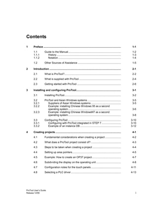
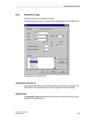
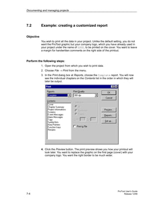
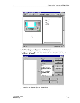
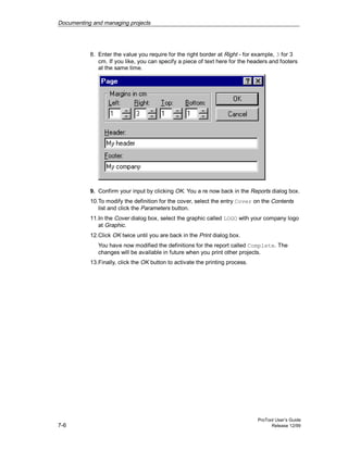
The document provides information about ProTool configuration software including installing and configuring ProTool, creating projects, configuration techniques, testing projects, and documenting and managing projects. It assumes the reader has experience with Windows applications and configuring PLCs.


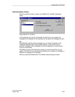
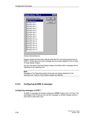
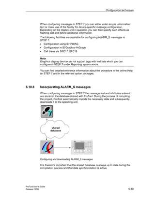
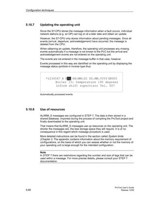

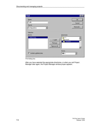
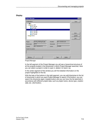


![2711e um006 -en-p[1]](https://cdn.slidesharecdn.com/ss_thumbnails/2711e-um006-en-p1-120514065850-phpapp02-thumbnail.jpg?width=640&height=640&fit=bounds)


