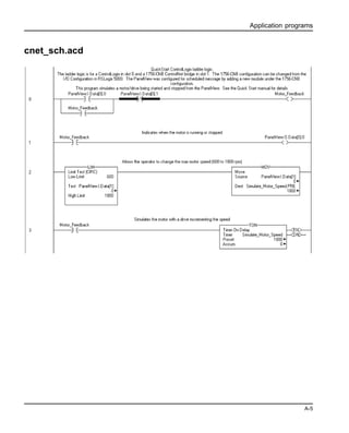
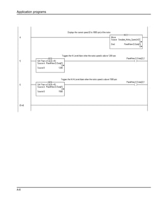
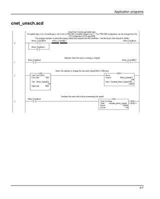
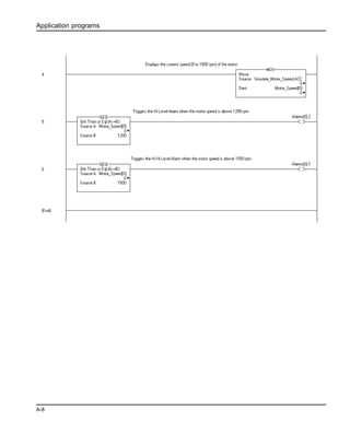
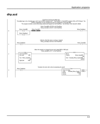
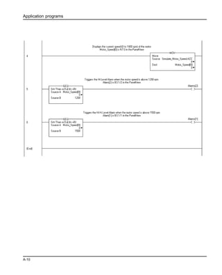
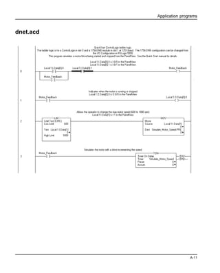
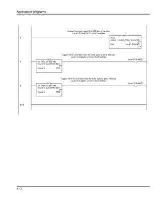
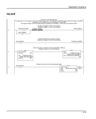
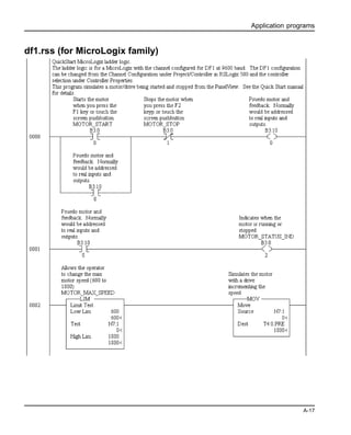
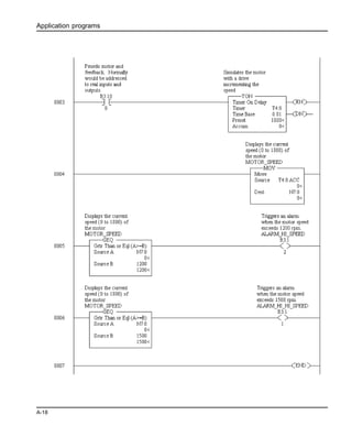
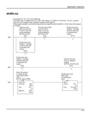
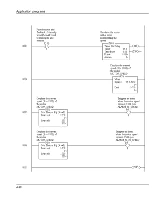
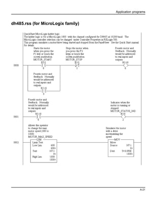
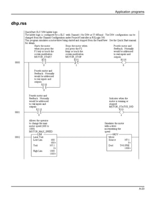
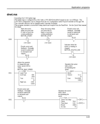
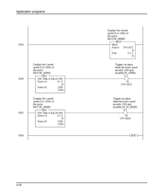
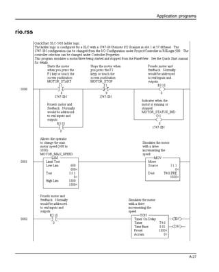
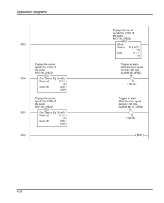
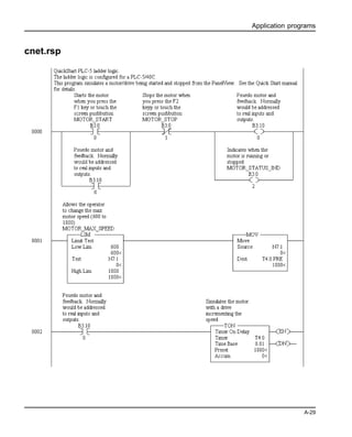
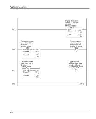
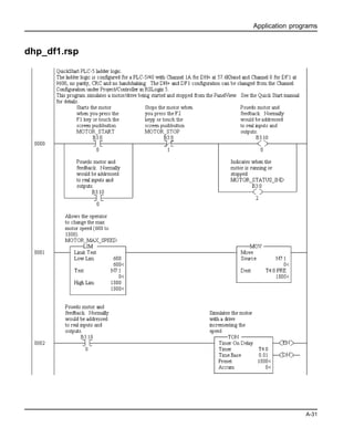
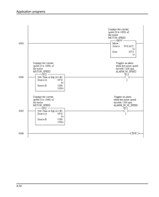
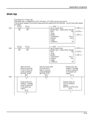
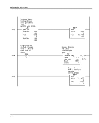
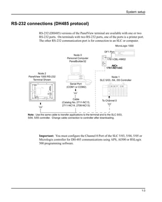
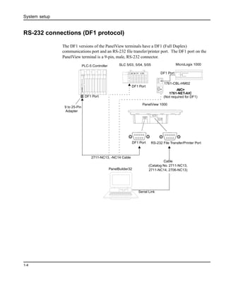
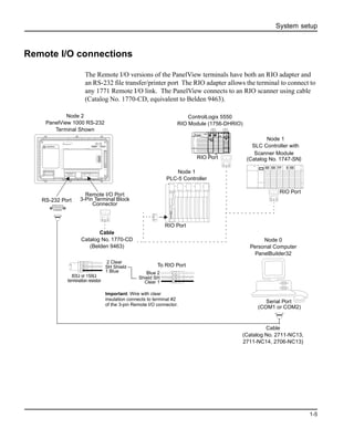
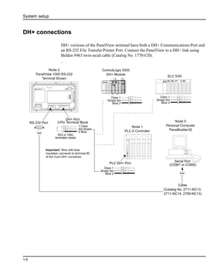
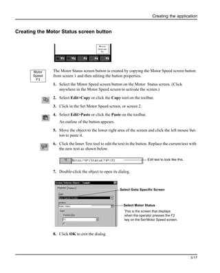
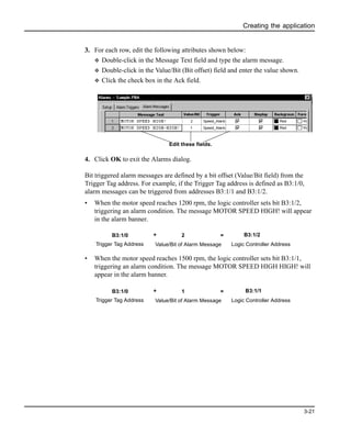
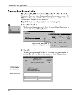
This document provides instructions for creating and downloading a PanelView application that controls a motor. The application includes two screens - a Motor Status screen to start and stop the motor and view its speed/status, and a Set Motor Speed screen to set the target speed. Objects like buttons, displays and indicators are created on the screens and linked to PLC tags to control the motor and display feedback. The application is then downloaded to the PanelView terminal to run.


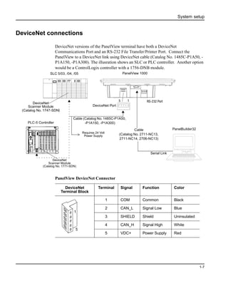
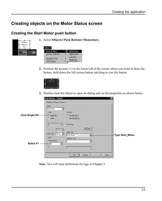
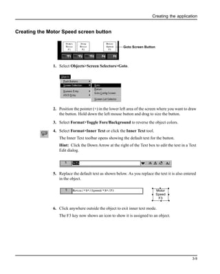
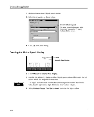
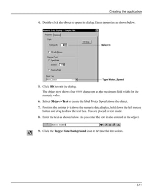
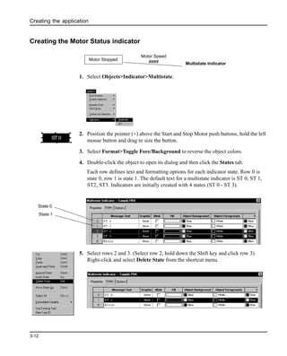
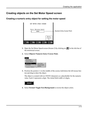
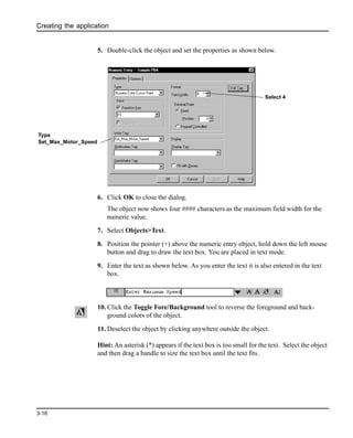
![Creating the application
3-24
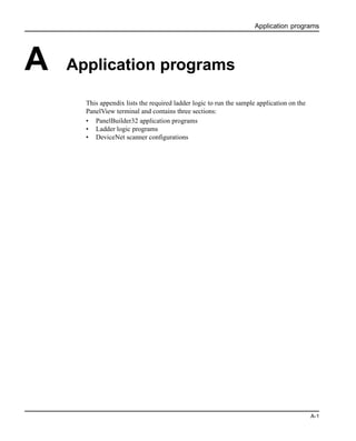
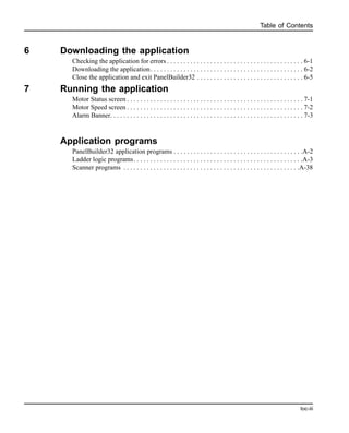
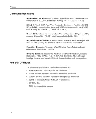
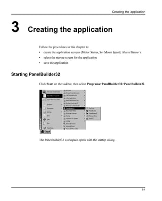
Converting application for another terminal type
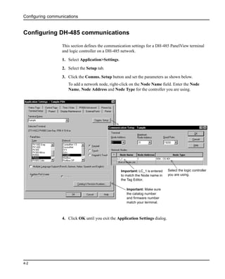
The sample application was created for the PanelView 600 keypad terminal and is
available for DH-485, DH+, DF1, Remote I/O, DeviceNet and ControlNet protocols.
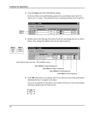
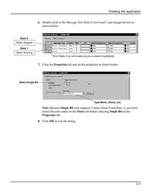
You can convert any one these applications to another terminal size such as
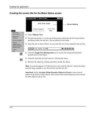
PanelView 1000 by following the procedure below.
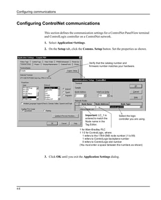
1. Select Application>Settings.
2. Click the Setup tab.
3. Select the PanelView terminal for which you want to convert the application.
4. When you click OK, the application is converted and validated for any errors.
If the application is converted successfully, the Exceptions window shows the
message:
[Application] Conversion Passed - No Errors Found
Important: Depending on the terminal size, you may want to reposition and resize
objects appropriately. You may also want to adjust the text sizes.
If the terminal uses a different protocol, you can select the Convert option on the Edit
Tag tab of the Tools>Options dialog and the tag editor will convert the current tags to
the appropriate fields for the new protocol. You still need to update the tag data.](https://image.slidesharecdn.com/pb32x-150826053849-lva1-app6892/85/Pb32x-50-320.jpg)

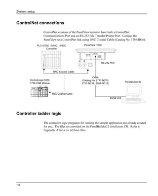
![Entering application tags
5-3
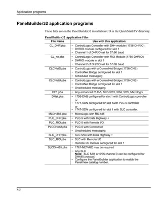
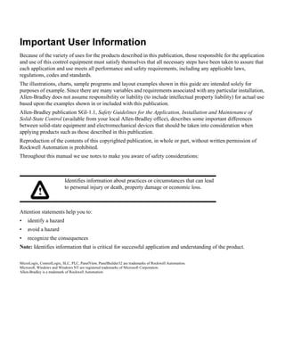
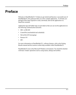
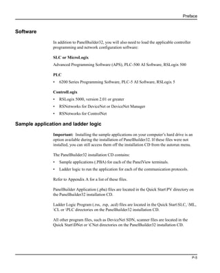
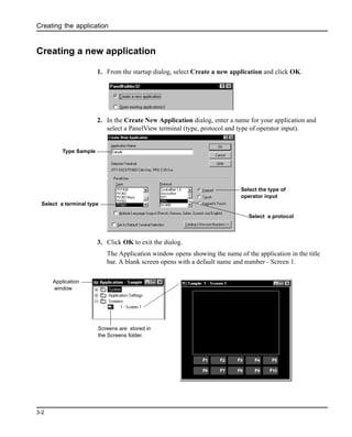
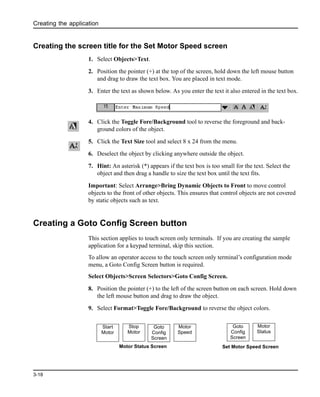
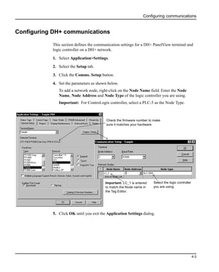
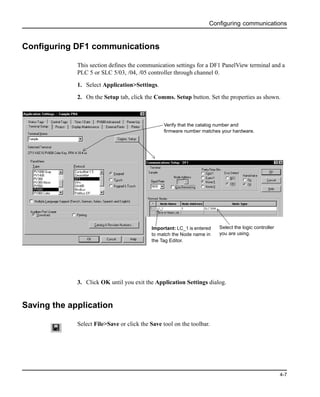
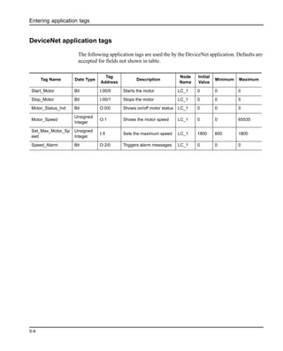
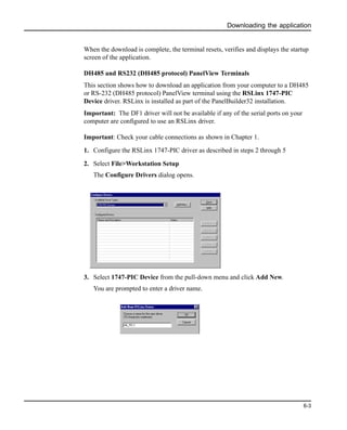
ControlNet unscheduled application tags
The following application tags are used by the ControlNet application using
unscheduled messaging. Note: Tags are shown for a ControlLogix application.
Defaults are accepted for fields not shown in table.
ControlNet scheduled application tags
The following application tags are used by the ControlNet application using
scheduled messaging. Defaults are accepted for fields not shown in table.
Tag Name Date Type Tag Address Description
Node
Name
Initial
Value
Minimum Maximum
Start_Motor Bit Motor_Control.00 Starts the motor LC_1 0 0 0
Stop_Motor Bit Motor_Control.01 Stops the motor LC_1 0 0 0
Motor_Status_Ind Bit Motor_Control.02
Shows on/off
motor status
LC_1 0 0 0
Motor_Speed
Signed
Integer/INT
Motor_Speed[0]
Shows the motor
speed
LC_1 0 -32768 32767
Set_Max_Motor_Sp
eed
Signed
Integer/INT
Motor_Speed[1]
Sets the
maximum speed
LC_1 1800 600 1800
Speed_Alarm Bit Alarms.00
Triggers alarm
messages
LC_1 0 0 0
Tag Name
Date
Type
Tag
Address
Description
Node
Name
Initial
Value
Minimum Maximum
Start_Motor Bit SI0:0/0
Starts the
motor
ControlNet_Scheduled
_File
0 0 0
Stop_Motor Bit SI0:0/1
Stops the
motor
ControlNet_Scheduled
_File
0 0 0
Motor_Status_Ind Bit SO0:0/0
Shows on/off
motor status
ControlNet_Scheduled
_File
0 0 0
Motor_Speed
Signed
Integer/
INT
SO0:1
Shows the
motor speed
ControlNet_Scheduled
_File
0 -32768 32767
Set_Max_Motor_Sp
eed
Signed
Integer/
INT
SI0:1
Sets the
maximum
speed
ControlNet_Scheduled
_File
1800 600 1800
Speed_Alarm Bit SO0:2/0
Triggers
alarm
messages
ControlNet_Scheduled
_File
0 0 0](https://image.slidesharecdn.com/pb32x-150826053849-lva1-app6892/85/Pb32x-61-320.jpg)

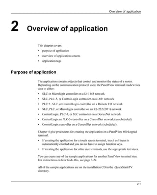
![Running the application
7-1
7 Running the application
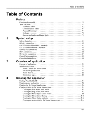
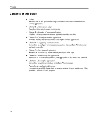
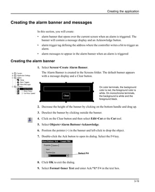
This chapter provides some guidance in checking the operation of the application.
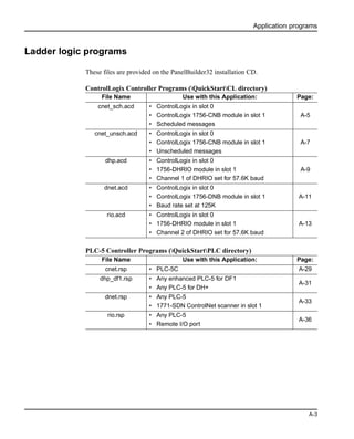
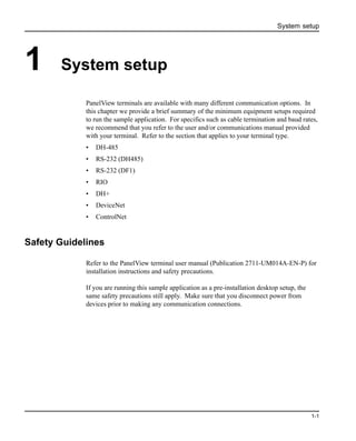
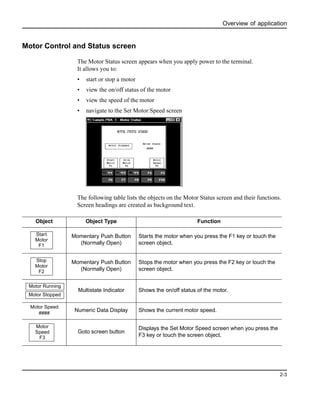
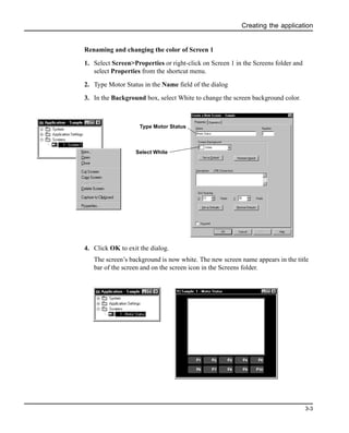
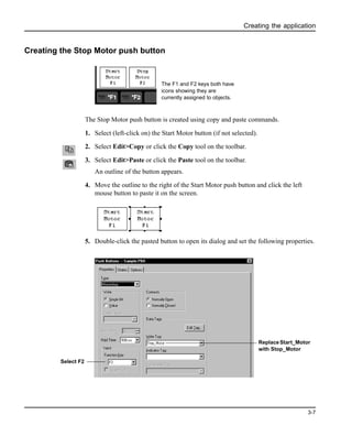
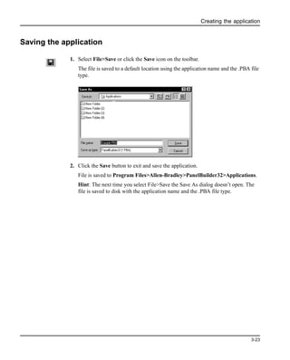
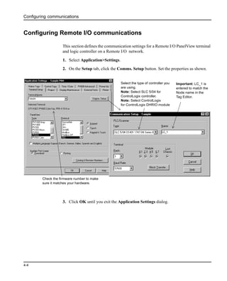
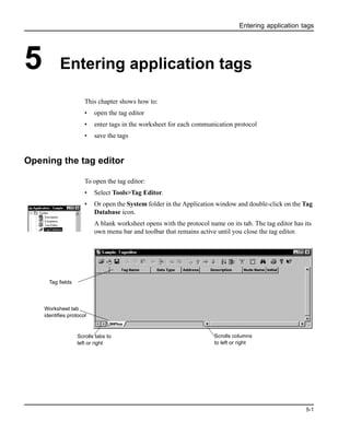
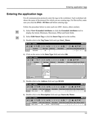
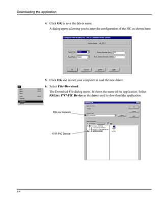
Motor Status screen
After receiving the downloaded application, the PanelView terminal displays the
Motor Status screen.
To start/stop the motor:
1. Press the [F1] key. On touch screens, touch
Notice how the Start / Stop Motor push button changes each time it is pressed.
2. Stop the motor by pressing [F2] or on touch screens
Notice that the stop button also changes inner text each time it is pressed.
Start
Motor
F1
Stop
Motor
F2
Motor
Status
F3
Motor Stopped Motor Speed
568
MOTOR STATUS SCREEN
Start
Motor
F1
Start
Motor
F1
Motor
Started
Stop
Motor
F2
Stop
Motor
F2
Motor
Stopped](https://image.slidesharecdn.com/pb32x-150826053849-lva1-app6892/85/Pb32x-71-320.jpg)
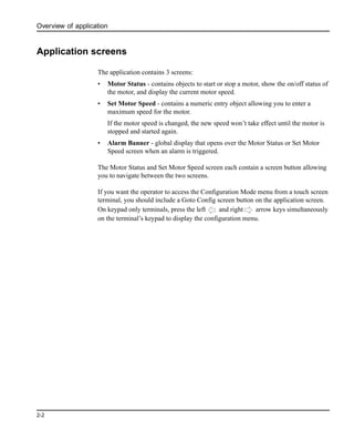
![Running the application
7-2
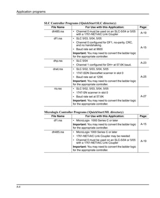
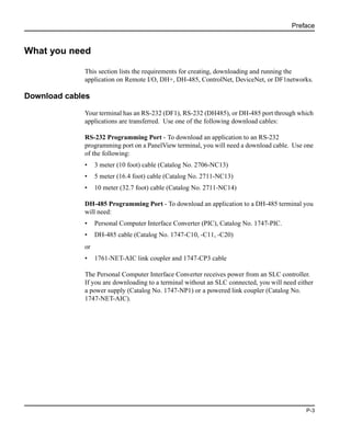
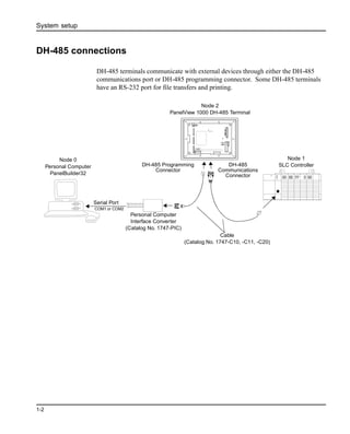
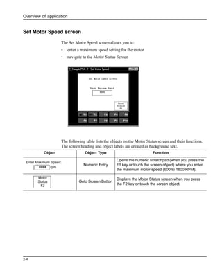
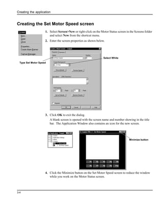
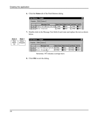
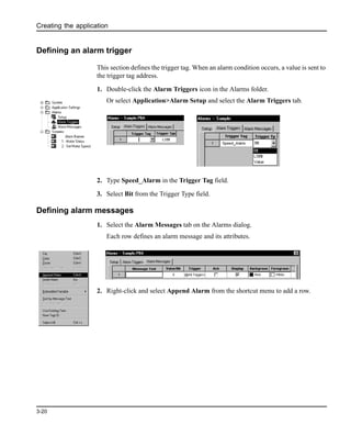
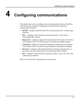
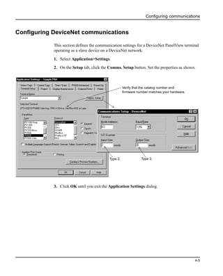
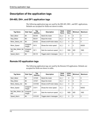
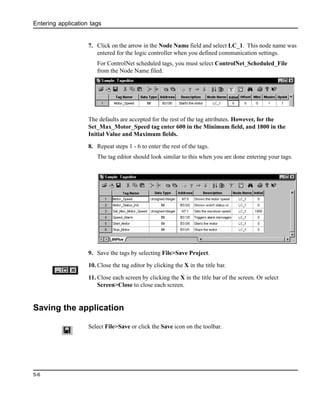
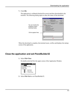
3. Press the Motor Start/Stop buttons and note how the motor status indicator also
changes.
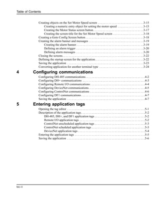
Motor Speed screen
Access the Motor Speed Screen by pressing [F3]. On touch screens, touch
To enter a motor speed:
1. Press the [F1] key. On touch screens, touch
The numeric entry scratchpad opens
Motor Running
Motor Stopped
Start
Motor
F1
Stop
Motor
F2
Motor
Status
F3
Motor Stopped Motor Speed
568
MOTOR STATUS SCREEN
Motor
Speed
F3
Motor
Status
F2
SET MOTOR SPEED SCREEN
Enter Maximum Speed
850
Enter Maximum Speed
####
Keypad and Keypad/Touch Screen550 Touch Screen only
Terminal Scratchpad
900/1000/1400Touch Screen
Terminal Scratchpad
Terminal Scratchpad
Current value entered in scratchpad](https://image.slidesharecdn.com/pb32x-150826053849-lva1-app6892/85/Pb32x-72-320.jpg)
![Running the application
7-3
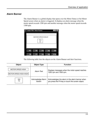
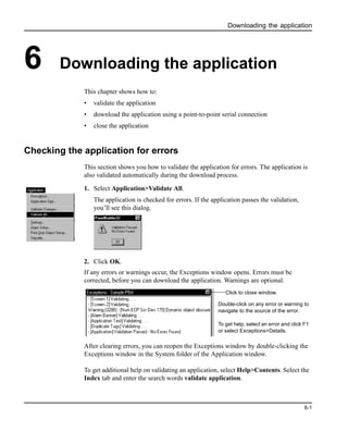
2. Enter a motor speed between 600 and 1800 on the scratchpad using the numeric
entry keys. On touch screens, touch the numeric keys displayed on the screen.
Note: During data entry, wait until the number you enter appears in the
scratchpad before entering the next number.
3. Press Enter (↵) to save the value and close the scratchpad.
4. Press the [F2] key. On touch screens, touch
Notice the new motor speed displayed on the Status screen.
The new speed will not take effect until the motor is stopped and restarted.
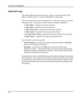
Alarm Banner
Create an alarm condition by entering a motor max speed between 1200 - 1500 as
described in the previous section and then starting the motor. An alarm banner is
displayed over the current screen.
5. To acknowledge the alarm, press the [F4] key. On touch screens, touch
The alarm banner is cleared.
Note: When the motor speed is in the range 1500 -1800 rpm, a different alarm
message is displayed.
Motor
Status
F2
Motor Stopped Motor Speed
568
MOTORSTATUSSCREENMOTOR SPEED HIGH!
Ack
F4
Stop
Motor
F2
Start
Motor
F1
Motor
Status
F3
Ack
F4](https://image.slidesharecdn.com/pb32x-150826053849-lva1-app6892/85/Pb32x-73-320.jpg)