This document provides information about Denso's Common Rail System (CRS) used in Hino medium trucks, including:
- Applicable vehicle and engine models from 2004-2010.
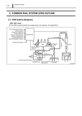
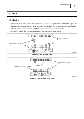
- An overview of the CRS components and operation.
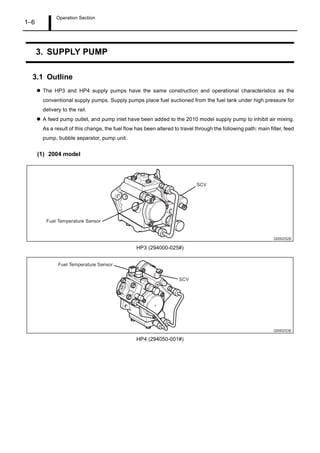
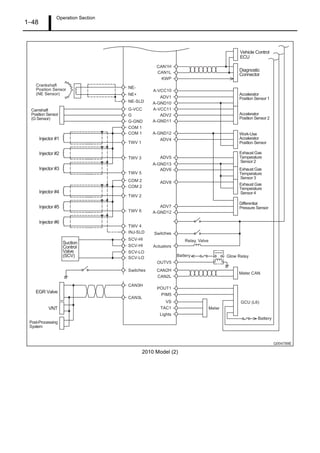
- Details on the supply pump, rail, injectors, engine ECU, sensors and exhaust gas control systems.
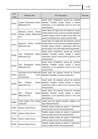
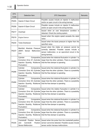
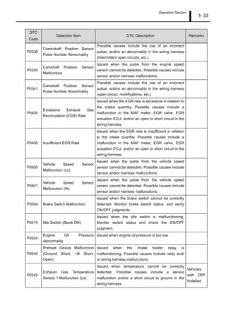
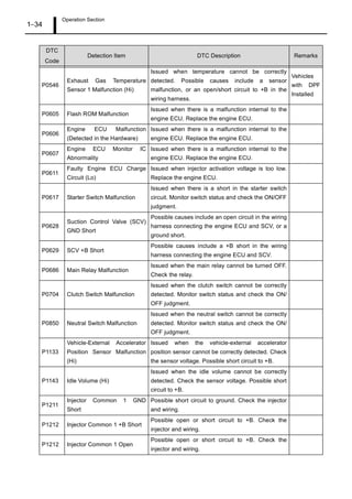
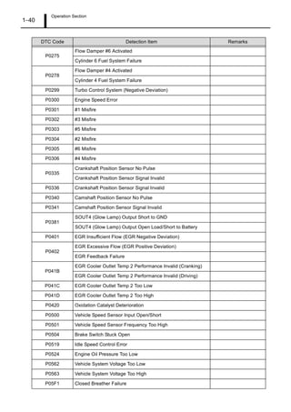
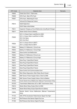
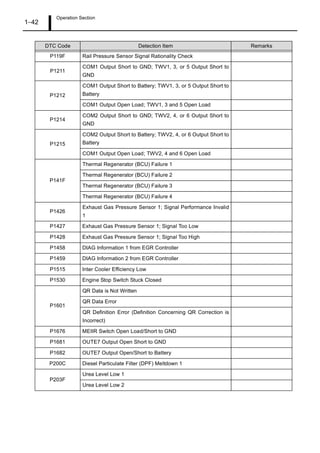
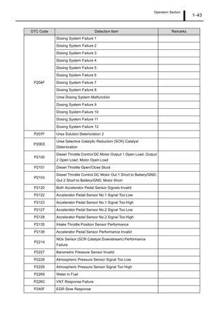
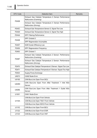
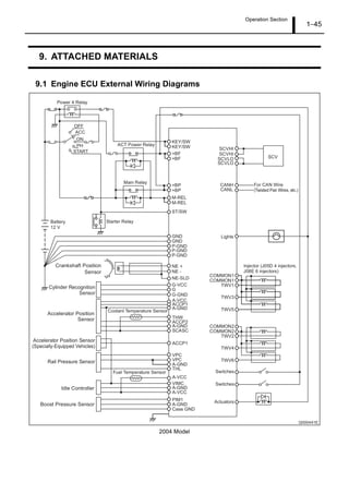
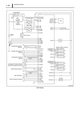
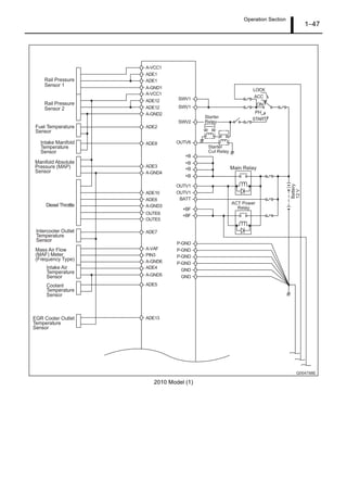
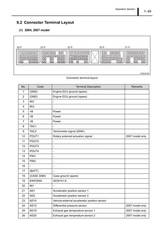
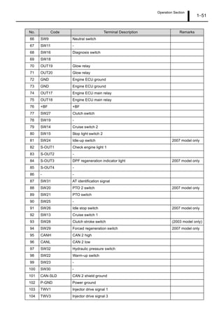
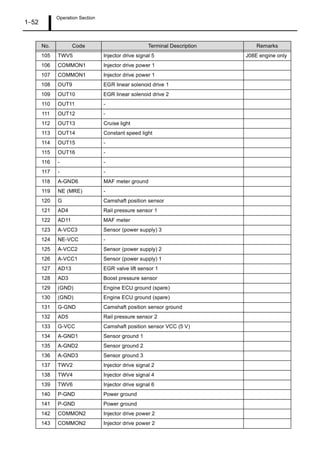
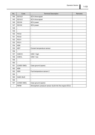
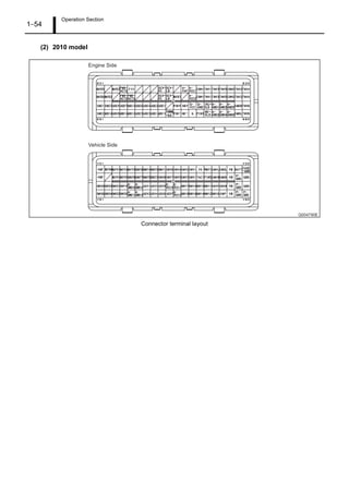
- Diagnostic trouble codes and wiring diagrams for the engine ECU.
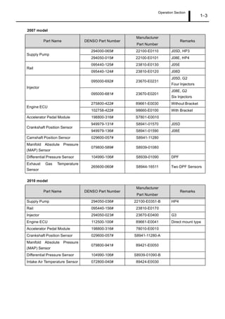
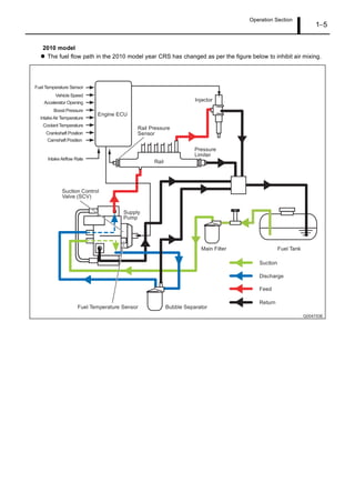
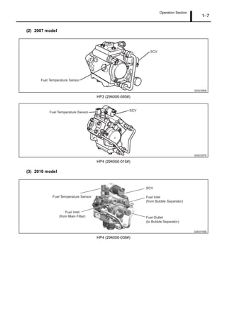
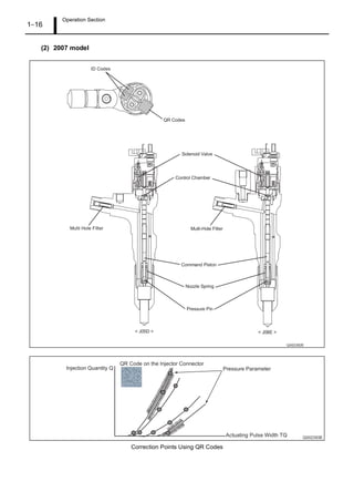
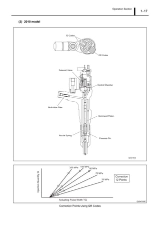
It describes updates made to the CRS in 2007 and 2010, including changes to components, increased injection pressure, and the addition of a selective catalytic reduction system to the 2010 model.
![Operation Section
1 1
1. APPLICABLE VEHICLE AND PRODUCT INFORMATION
1.1 Introduction
This manual describes the Common Rail System (CRS) equipped with J05D/J08E engines used in the
HINO Medium Truck.
For information on items common to all CRSs, refer to the previously published CRS general addition
manual (Doc ID: 00400076E). [Items common to all CRSs: CRS development process, system control,
construction and operation of main components (supply pump, rail, injectors), sensors and actuators]
Minor changes have been made to the HINO medium truck as of June 2010. With this minor change, the
CRS equipped with the J08E engine has also changed, and now this engine uses the Selective Catalytic
Reduction (SCR) system. The SCR system dramatically reduces the quantity of NOx exhaust, and achieves
superior environmental protection functionality suited to the stringent emission standards stipulated in the
"US10" regulations.
Changes to the CRS are shown below.
Maximum injection pressure increased to 200 MPa.
Fuel path related with the supply pump changed.
Rail is compliant with a pressure of 200 MPa.
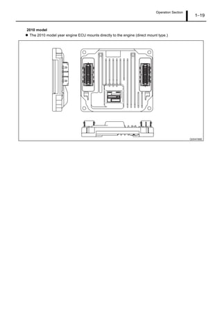
Engine ECU changed to a direct-mount type.
CRS now equipped with G3 type injectors.
The J08E engine now uses the Selective Catalytic Reduction (SCR) system.
1.2 Applicable Vehicles
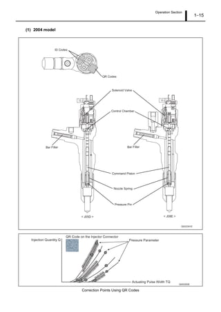
2004 model
Vehicle Type Vehicle Model Engine Model
Engine
Displacement
Release Date
Medium Truck
HINO145
HINO165
HINO185
J05D 4.73 L
April 2004
HINO238
HINO268
HINO308
HINO338
J08E 7.68 L](https://image.slidesharecdn.com/hinoj05dj08eengine1-220818153050-4188418a/85/HINO-J05D-J08E-Engine-1-pdf-4-320.jpg)