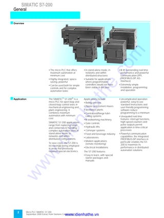
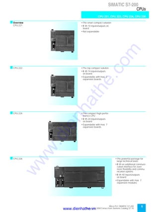
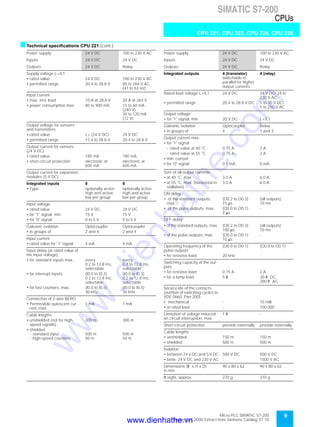
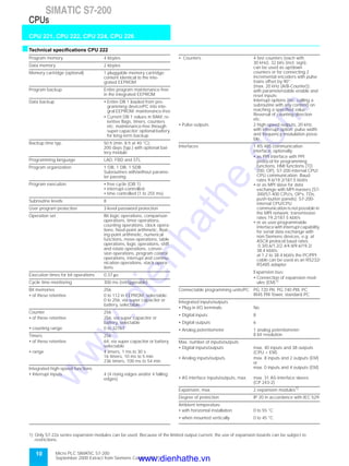
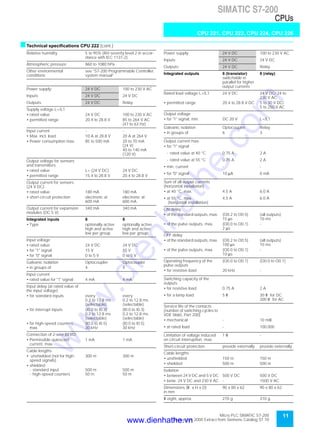
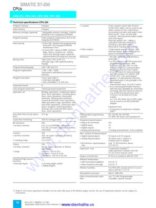
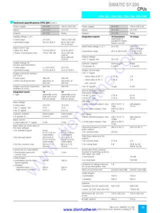
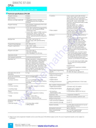
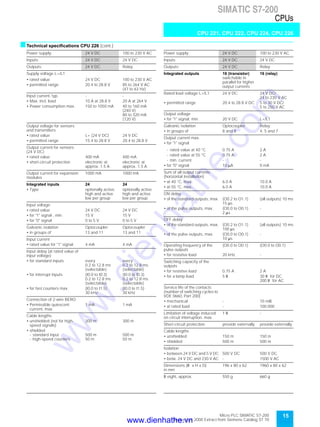
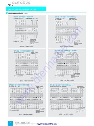
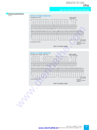
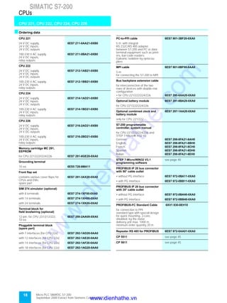
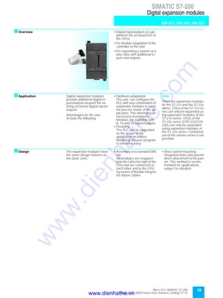
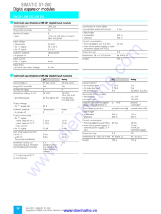
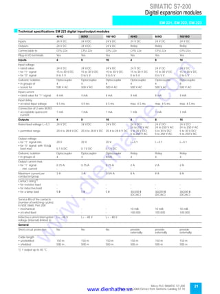
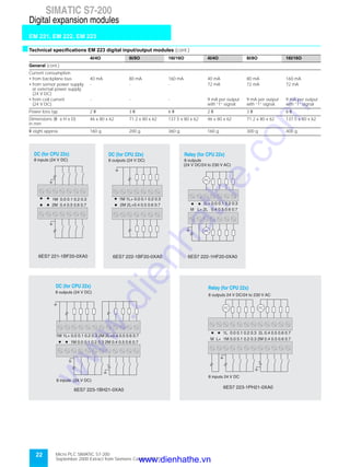
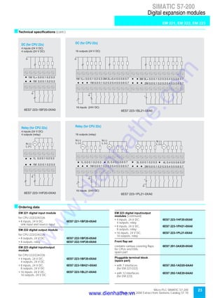
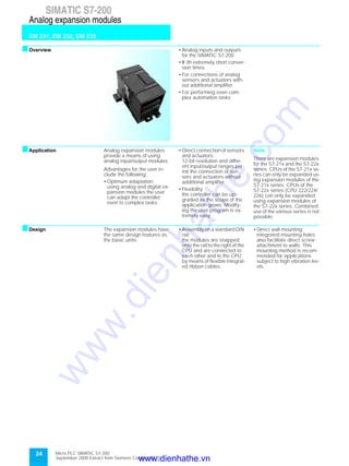
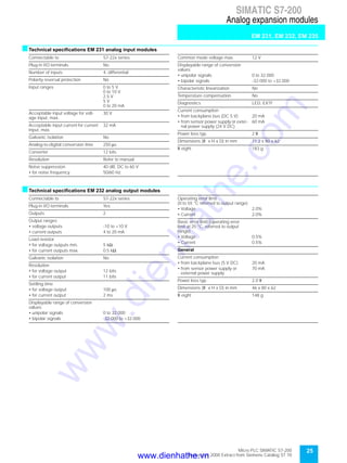
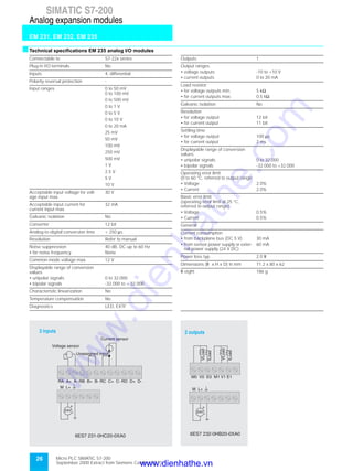
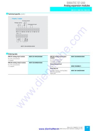
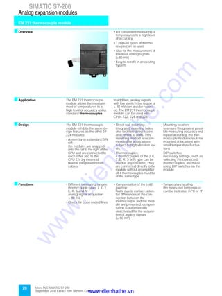
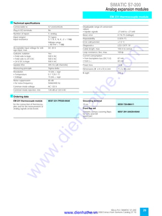
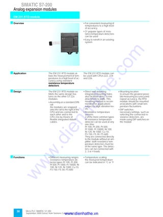
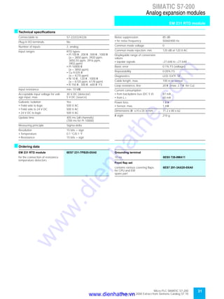
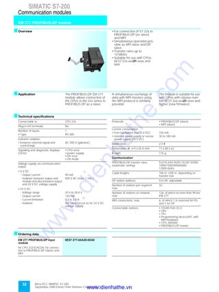
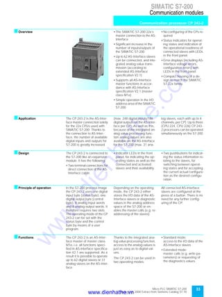
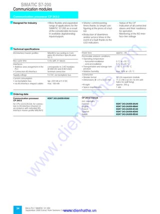
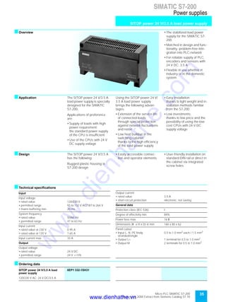
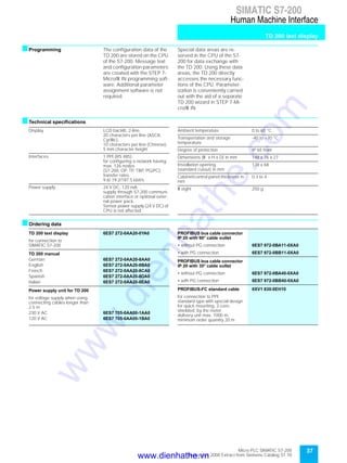
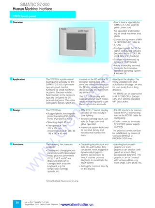
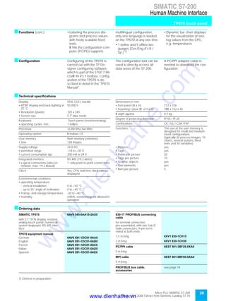
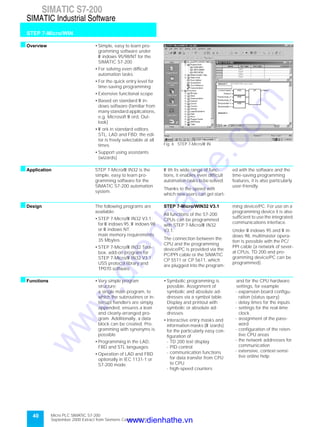
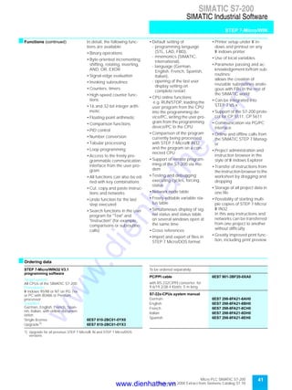
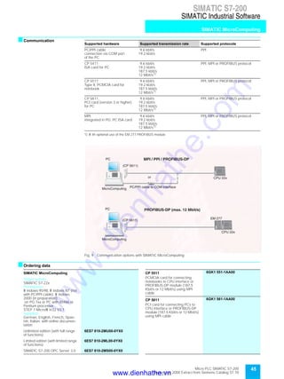
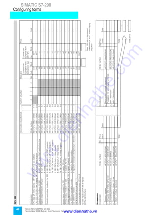
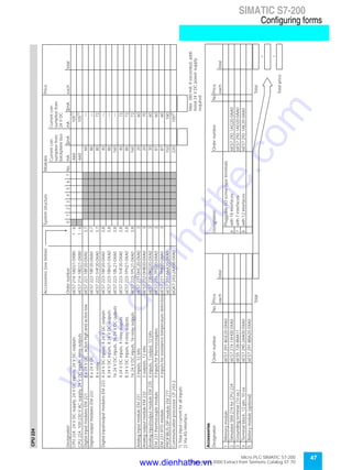
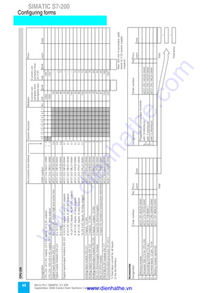
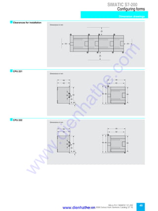
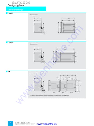
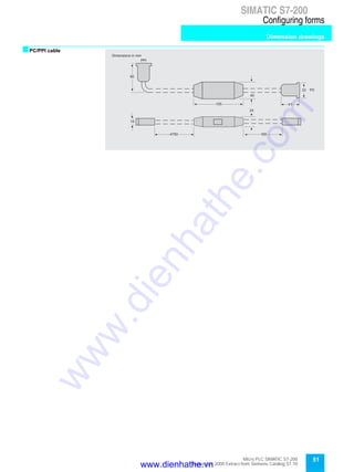
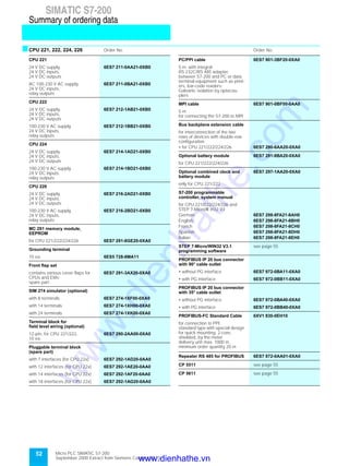
General
2
CPUs
5
Digital expansion modules
19
Analog expansion modules
24
Communication modules
32
Power supplies
35
Human Machine Interface
36
SIMATIC Industrial Software
40
Configuring forms
46
Summary of ordering data
52
Appendix
56
s
The products and systems
described in this catalog are sold
under application of a quality
management system certified
by DQS in accordance with
DIN EN ISO 9001 (Certificate
registration No.: 1323-03).
The DQS Certificate is re-
cognized in all EQ Net countries
(Reg. No.: 1323).
SIMATIC
Micro PLC
SIMATIC S7-200
Extract from Catalog ST 70
Edition September 2000
Supersedes:
Extract SIMATIC S7-200 from Catalog ST 70,
Edition August 1999
For further information
contact your local
Siemens representative
The products listed in this catalog
are also available from
the CD-ROM Catalog CA 01.
Order No.:
E86060-D4001-A100-B4-7600
Page
www.dienhathe.vn
www.dienhathe.com
2 Micro PLC SIMATIC S7-200
September 2000 Extract from Siemens Catalog ST 70
SIMATIC S7-200
General
SIMATIC S7-200
sOverview
• The micro PLC that offers
maximum automation at
minimum cost
• Highly integrated, space-
saving, powerful
• Can be used both for simple
controls and for complex
automation tasks
• In stand-alone mode, in
networks and within
distributed structures
• Suitable for applications
where programmable
controllers would not have
been viable in the past
• W ith outstanding real-time
performance and powerful
communication (PPI,
PROFIBUS-DP, AS-
Interface)
• Extremely simple
installation, programming
and operation
sApplication The SIMATIC®
S7-200®
is a
micro PLC for open-loop and
closed-loop control tasks in
mechanical engineering and
plant engineering. It
combines maximum
automation with minimum
cost.
SIMATIC S7-200 applications
range from replacing relays
and contactors to handling
complex automation tasks in
stand-alone mode, in
networks and within
distributed configurations.
To save costs, the S7-200 is
increasingly being employed
in areas that previously
required special electronics.
Applications include:
• Baling presses
• Plaster and cement mixers
• Ventilation plants
• Centralized/flange lubri-
cating systems
• W oodworking machinery
• Gate controls
• Hydraulic lifts
• Conveyor systems
• Food and beverage industry
• Laboratories
• Modem applications
(remote monitoring)
• Electrical installations
The S7-200 features:
• Easy to learn, with special
starter packages and
manuals
• Uncomplicated operation;
powerful, easy-to-use
standard instructions and
user-friendly programming
software reduce
programming to a minimum
• Unequaled real-time
features; interrupt functions,
high-speed counters and
pulse outputs permit
application in time-critical
processes
• Powerful communication
capabilities; the integrated
PROFIBUS-DP interface in
particular enables the S7-
200 to maximize its
performance in distributed
automation solutions.
www.dienhathe.vn
www.dienhathe.com
Micro PLC SIMATIC S7-200
September 2000 Extract from Siemens Catalog ST 70
3
SIMATIC S7-200
General
sDesign The SIMATIC S7-200 family
consists of the following
modules:
• 4 different basic units in
different variants
• 14 digital and analog
expansion modules
• 2 communications modules
for connecting to PROFIBUS
and AS-Interface
Mechanical features
• Rugged, compact plastic
housing
• Easily accessible wiring and
operator control elements
protected by front covers
Design features
• International standards; the
SIMATIC S7-200 meets the
requirements through
compliance with VDE, UL,
CSA and FM (Class I,
Division 2, hazardous area
groups A, B, C and D, T4A)
standards. The quality
management system used
during manufacturing has
ISO 9001 certification.
sCommunication The SIMATIC S7-200 offers
various communication
capabilities:
• Point-to-point interface; can
be operated in PPI, MPI
(slave) mode and in user-
programmable interface
mode
• AS-Interface connection; as
master via the CP 243-2
communication processor
• Connection to PROFIBUS-
DP as slave; via the
PROFIBUS-DP module
EM 277
PPI network
PPI is the communications
system integrated in every S7-
200 CPU. Connections for pro-
gramming or for human machi-
ne interface functionality can
be established over a shared
twisted-pair cable. The CPUs
can communicate with several
other CPUs, TDs or OPs
simultaneously
The data transfer rate is 9.6/
19.2/187.5 kbit/s. The
following can be connected:
• PG 720PII, PG 740PIII,
PC RI45 PIII Tower
programming devices
• PCs (AT-compatible), via PC/
PPI cable
• TD 200 text display; SIMATIC
OP operator panels
• SIMATIC S7-200; up to 31
S7-200s can be operated on
a shared data bus with a
programming device, PC, TD
200 or OP. Direct data ex-
change between S7-200
controllers (in each case as a
master) with the NETR and
NETW commands.
MPI network
All CPUs can be connected to
an MPI network (19.2/187.5
kbit/s) via the integrated
interface and can then
communicate with SIMATIC
S7-300®
s/S7-400®
s. The S7-
200 CPUs are slaves in the
MPI-network and cannot
communicate with each other.
Fig. 1 Communication in PPI mode
Fig. 2 Communication in PPI mode
Programming device/PC
PC via PC/PPI cable
or MPI card
S7-200
S7-200
S7-200
SIMATIC OP
TD 200
PPI network
SIMATIC OP
S7-400
S7-300
S7-200
MPI network
Progr. device/PC
PC via MPI card
www.dienhathe.vn
www.dienhathe.com
4
SIMATIC S7-200
General
Micro PLC SIMATIC S7-200
September 2000 Extract from Siemens Catalog ST 70
sCommunication (cont.) Point-to-point interface,
user-programmable
interface mode
Connection to the RS 232
interface via PC/PPI cable.
Data transmission is
performed with the CPU in
FreePort mode; in the case of
the CPU 226, both ports can
be operated in FreePort
mode. Data exchange takes
place using a user-specific,
bit-oriented communications
protocol (e.g. ASCII protocol
or Modbus). Maximum data
transmission rate 38.4 kbit/s
(adjustable).
Point-to-point connections are
possible to the following units:
• Any data terminal equipment
which has a serial interface,
e.g. printers, bar-code
readers
• S7-200 micro PLC; e.g. for
simple data exchange
between two CPUs
AS-Interface
The SIMATIC S7-200 is
connected to the AS-Interface
as a master via the CP 243-2.
This increases the number of
inputs and outputs appre-
ciably:
• Up to 31 AS-Interface slaves
with up to 248 binary
elements
PROFIBUS-DP slave
PROFIBUS-DP guarantees
integrated and uniform
communication between all
SIMATIC system components
while at the same time
maintaining an open system.
PROFIBUS-DP’s high data
transfer rate (up to 12 Mbit/s)
over the integrated interface
allows the real time features of
the S7-200 to be used to their
full extend within a distributed
system structure.
Response times in the millise-
cond range enable applica-
tions such as the following:
• Motor synchronization
• Interrupt-oriented applica-
tions
• Coordination of high-speed
counting processes
Fig. 3 Communication in user-programmable interface mode
Fig. 4 Communication via AS-Interface
Fig. 5 Communication via PROFIBUS-DP
S7-200
SONAR BERO
with int. AS-Interface
Inductive BERO
with int. AS-Interface
Operator panel
SIMATIC S7-300
0 1
ET 200
S7-200
SIMATIC S7-400
SIMATIC OP
SIMATIC C7
Programming device
SIMATIC S5
Printer Barcode reader
S7-200
S7-200 Modem
www.dienhathe.vn
www.dienhathe.com
Micro PLC SIMATIC S7-200
September 2000 Extract from Siemens Catalog ST 70
5
SIMATIC S7-200
CPUs
CPU 221, CPU 222, CPU 224, CPU 226
sOverview
CPU 221
• The smart compact solution
• W ith 10 inputs/outputs on
board
• Not expandable
sCPU 222 • The top compact solution
• W ith 14 inputs/outputs
on board
• Expandable with max. 2
expansion boards
sCPU 224 • The compact high-perfor-
mance CPU
• W ith 24 inputs/outputs
on board
• Expandable with max. 7
expansion boards
sCPU 226 • The powerful package for
large technical tasks
• W ith an additional communi-
cation interface for even
more flexibility and commu-
nication options
• W ith 40 inputs/outputs
on board
• Expandable with max. 7
expansion modules
www.dienhathe.vn
www.dienhathe.com
Micro PLC SIMATIC S7-200
September 2000 Extract from Siemens Catalog ST 70
6
SIMATIC S7-200
CPU 221, CPU 222, CPU 224, CPU 226
CPUs
sApplication CPU 221
The smart compact solution,
with 10 inputs/outputs on
board, cannot be extended.
CPU 222
The superior compact
solution with 14 inputs/outputs
on board, expandable with
max. 2 expansion boards.
CPU 224
The compact high-perfor-
mance CPU, with 24 inputs/
outputs on board, expandable
with max. 7 expansion
boards.
CPU 226
The power pack for complex
technical tasks. W ith
additional communication
interface for added flexibility
and communication options.
W ith 40 inputs/outputs on
board, expandable with max.
7 expansion boards.
sDesign The CPUs include:
• Integrated 24 V sensor/load
power supply; for the direct
connection of sensors and
encoders. W ith 180 mA
(CPU 221/222), 280 mA
(CPU 224), 400 mA
(CPU 226) it can also be
used as a load power supply
• 2 device variants;
with different supply and
control voltages
• Integrated digital inputs/
outputs;
CPU 221:
6 inputs and 4 outputs;
CPU 222:
8 inputs and 6 outputs;
CPU 224:
14 inputs and 10 outputs;
CPU 226:
24 inputs and 16 outputs
• CPU 221/222/224:
1 communication interface;
CPU 226:
2 communication interfaces;
optionally
- as PPI interface with PPI
protocol for programming
functions, HMI®
functions
(TD 200, OP), S7-200-
internal CPU/CPU
communication (9.6/19.2/
187.5 kbit/s) or as MPI
slave for data exchange
with MPI masters (S7-300/-
400, OPs, TDs, Push
Button Panels)
- user-programmable
interface (FreePort) with
interrupt capability for
serial data exchange with
non-Siemens devices, e.g.
at the ASCII protocol baud
rates 0.3/0.6/1.2/2.4/4.8/
9.6/19.2/38.4 kbit/s;
PC/PPI cable can be used
as RS 232/RS 485 adapter
• CPU 222/224/226:
Expansion bus; connection
of expansion modules (only
EMs of the 22x series can be
used)
• Interrupt inputs; for
extremely fast responses to
rising or falling edges of
process signals
• High-speed counters;
CPU 221/222:
4 high-speed counters
(30 kHz);
CPU 224/226:
6 high-speed counters
(30 kHz), with parameteriza-
ble enable and reset inputs
that can be used
simultaneously as up and
down counters with two
separate inputs and for
connecting incremental
encoders wtih two pulse
sequences (20 kHz) with a
90° offset
• CPU 222/224/226:
Trouble-free expandability
through digital and analog
expansion modules (EM’s)
• Simulator (optional);
for the simulation of
integrated inputs and the
testing of user programs
• Analog potentiometers;
CPU 221/222:
1 analog potentiometers;
CPU 224/226:
2 analog potentiometers,
can be used as a user-
friendly setpoint adjuster
during everyday operation,
such as for setting timers
• Pulse outputs;
2 high-frequency pulse
outputs (max. 20 kHz); For
use in positioning tasks and
the control of frequency-
regulated motors and
stepper motors via power
circuits
• Real-time clock
(for insertion as optional
module CPU 221/222);
for example for adding time
stamps to messages, for
registering machine running
times or for the time-control
of processes
• EEPROM cartridge (can
optionally be inserted);
allows rapid program
change (even without a
programming device) and
additional program
archiving
• Battery module for long-term
buffering; for extending the
buffering time to typically
200 days. W ithout the
battery module, user data
(e.g. memory bit statuses,
data blocks, timers,
counters) are saved by an
internal high-power
capacitor for around 5 days.
The program is always
saved in non-volatile
memory(maintenance-free).
The battery module is
inserted into the memory
submodule slot.
www.dienhathe.vn
www.dienhathe.com
Micro PLC SIMATIC S7-200
September 2000 Extract from Siemens Catalog ST 70
7
SIMATIC S7-200
CPUs
CPU 221, CPU 222, CPU 224, CPU 226
sDesign (cont.)
Device versions
sFunctions • Extensive set of instructions;
A multiplicity of
- basic operations such as
binary logic operations,
result allocation, save,
count, create times, load,
transfer, compare, shift,
rotate, create complement,
call sub-program (with
local variables)
- integrated communication
commands (eg. S7-200
communication (Network
read NETR, Network write
NETW ) or Freeport
(Transmit XMT, Receive
RCV)) and
- enhanced functions such
as pulse-duration
modulation, pulse
sequence function, arith-
metic functions, floating
point arithmetic, PID
closed-loop control, jump
functions, loop functions
and code conversions
simplify the programming
task
• Counting;
user-friendly counting
functions in conjunction with
the integrated counters und
special commands for the
High Speed Counter open
up new application areas for
the user
• Interrupt handling;
- Edge-triggered interrupts
(triggered by either rising
or falling edges of process
signals at interrupt inputs)
permit extremely fast
reactions to process inter-
rupts
- Time-controlled interrupts
can be set in at 1 ms incre-
ments from 5 ms to 255 ms
- Counter interrupts can be
triggered when a specified
value is reached or if the
counter direction changes
- Communication interrupts
allow the rapid and easy
exchange of information
with peripheral devices
such as printers or bar
code readers
• Direct interrogation and
control of inputs/outputs;
Inputs and outputs can also
be interrogated and set
independently of the cycle.
The controller can so react
quickly to process events
(e.g. direct resetting of
outputs when interrupt
occurs)
• Password protection; the
3-level password protection
concept safeguards effec-
tively your know-how. The
protection concept has the
following options for access
to the user program:
- Full access: The program
can be altered as desired.
- Read only: The program is
protected against unautho-
rized alteration. Testing,
adjustment of system
parameters and copying of
the program is allowed.
- Complete protection: The
program is protected
against alteration and un-
authorized readout and
copying. Adjustment of pa-
rameters is allowed.
• Test and diagnostic
functions;
User-friendly functions
support testing and
diagnostics: the complete
program is run over a prede-
termined number of cycles
and analyzed. Internal
parameters such as memory
bits, timers or counters are
logged at the same time
over a maximum of 124
cycles.
• ”Forcing” of inputs and
outputs during test and
diagnostic operation;
Inputs and outputs can be
set independently of cycle
and thus permanently, for
example to test the user
program.
• Runtime edit:
• During RUN mode,
programs can be edited and
modified programs can be
loaded into the CPU with a
mouse click without having
to interrupt the running
program
• Additional mathematical
functions, e.g. SIN, COS,
TAN, LN, EXP
CPU 224, CPU 226 in addi-
tion:
• Runtime edit:
During RUN mode, pro-
grams can be edited and
modified programs can be
loaded into the CPU with a
mouse click without having
to interrupt the running pro-
gram
• Additional mathematical
functions, e.g. SIN, COS,
TAN, LN, EXP
sProgramming The STEP®
7-Micro/W IN32 V3
programming package
permits complete
programming of all S7-200-
CPUs
Note
The CPU 22x cannot be
programmed using STEP 7-
Micro/DOS.
For programming via the seri-
al interface of the program-
ming device/PC, a PC/PPI
cable is required.
W hen using the STEP 7-Micro/
W in32 V3 programming soft-
ware, programming is also
possible via the SIMATIC CPs
CP 5511 or CP 5611 (see
Catalog IK PI) or the MPI
interface of the programming
device. This increases the
maximum permissible
transmission rate to
187.5 kbit/s.
Version Supply voltage Input voltage Output voltage Output current
CPU 221/222/224/226 DC outputs 24 V DC 24 V DC 24 V DC 0.75 A,
transistor
Relay outputs 85 to 264 V AC 24 V DC 24 V DC ,
24 to 230 V AC
2 A, relay
www.dienhathe.vn
www.dienhathe.com
8 Micro PLC SIMATIC S7-200
September 2000 Extract from Siemens Catalog ST 70
SIMATIC S7-200
CPU 221, CPU 222, CPU 224, CPU 226
CPUs
sTechnical specifications CPU 221
Program memory 4 kbytes
Data memory 2 kbytes
Memory cartridge (optional) 1 pluggable memory cartridge;
content identical to the inte-
grated EEPROM
Program backup entire program maintenance-free
in the integrated EEPROM
Data backup • entire DB 1 loaded from pro-
gramming device/PC into inte-
gral EEPROM; maintenance-free
• current DB 1 values in RAM, re-
tentive memory bits, timers,
counters etc. maintenance-free
through super capacitor;
optional battery for long-term
backup.
Backup time typ. 50 h (min. 8 h at 40 °C);
200 days (typ.) with optional bat-
tery module
Programming language LAD, FBD and STL
Program organization 1 OB, 1 DB, 1 SDB
Subroutines with/without parame-
ter passing
Program execution • free cycle (OB 1)
• interrupt-controlled
• time controlled (1 to 255 ms)
Subroutine levels 8
User program protection 3-stage password protection
Operation set Bit logic operations, comparison
operations, timer operations,
counting operations, clock opera-
tions, fixed-point arithmetic, float-
ing-point arithmetic, numerical
functions, move operations, table
operations, logic operations, shift
and rotate operations, conver-
sion operations, program control
operations, interrupt and commu-
nication operations, stack opera-
tions
Execution times for bit operations 0.37 µs
Cycle time monitoring 300 ms (retriggerable)
Bit memories 256
• of these retentive 0 to 112 in EEPROM, selectable;
0 to 256, via super capacitor or
battery, selectable
Counter 256
• of these retentive 256, via super capacitor or
battery, selectable
• Counting range 0 to 32767
Timers 256
• of these retentive 64, via super capacitor or battery,
selectable
• range 4 timers, 1 ms to 30 s
16 timers, 10 ms to 5 min
236 timers, 100 ms to 54 min
Integrated high speed functions
• Interrupt inputs 4 (4 rising edges and/or 4 falling
edges)
• Counters 4 fast counters (each with
30 kHz), 32 bits (incl. sign),
can be used as up/down
counters or for connecting 2
incremental encoders with pulse
trains offset by 90°;
(max. 20 kHz (A/B counter));
with parameterizable enable and
reset inputs;
Interrupt options (inc. calling a
subroutine with any content) on
reaching a specified value;
reversal of counting direction etc.
• Pulse outputs 2 high-speed outputs, 20 kHz,
with interrupt option; pulse width
and frequency modulation possi-
ble
Interfaces 1 RS 485 communication
interface, optionally:
• as PPI interface with PPI
protocol for programming
functions, HMI functions
(TD 200, OP), S7-200-internal
CPU/CPU communication; Baud
rates 9.6/19.2/187.5 kbit/s
• or as MPI slave for data
exchange with MPI masters (S7-
300/S7-400 CPU’s, OP’s, TDs,
push-button panels); S7-200-
internal CPU/CPU
communication is not possible in
the MPI network; transmission
rates 19.2/187.5 kbit/s
• or as user-programmable
interface with interrupt capability
for serial data exchange with
non-Siemens devices, e.g. at
ASCII protocol baud rates:
0.3/0.6/1.2/2.4/4.8/9.6/19.2/
38.4 kbit/s;
at 1.2 to 38.4 kbit/s the PC/PPI
cable can be used as an RS232/
RS458 adapter
Connectable programming units/PC PG 720 PII, PG 740 PIII,
PC RI 45 PIII Tower, standard PCs
Integrated inputs/outputs
• Plug-in I/O terminals No
• Digital inputs 6
• Digital outputs 4
• Analog potentiometer 1 analog potentiometer;
8 bit resolution
Max. number of inputs/outputs
• Digital inputs/outputs max. 6 inputs and 4 outputs (inte-
grated inputs/outputs);
no extension possible
• Analog inputs/outputs -
• AS-Interface inputs/outputs, max. -
Expansion, max. -
Degree of protection IP 20 in accordance with IEC 529
Ambient temperature
• with horizontal installation 0 to 55 °C
• when mounted vertically 0 to 45 °C
Relative humidity 5 to 95% (RH severity level 2 in
accordance with IEC 1131-2)
Atmospheric pressure 860 to 1080 hPa
Other environmental conditions see “S7-200 Programmable
Controller, system manual”
www.dienhathe.vn
www.dienhathe.com
9Micro PLC SIMATIC S7-200
September 2000 Extract from Siemens Catalog ST 70
SIMATIC S7-200
CPUs
CPU 221, CPU 222, CPU 224, CPU 226
sTechnical specifications CPU 221 (cont.)
Power supply: 24 V DC 100 to 230 V AC
Inputs: 24 V DC 24 V DC
Outputs: 24 V DC Relay
Supply voltage L+/L1
• rated value 24 V DC 100 to 230 V AC
• permitted range 20.4 to 28.8 V 85 to 264 V AC
(47 to 63 Hz)
Input current
• max. incl. load 10 A at 28.8 V 20 A at 264 V
• power consumption max. 80 to 900 mA 15 to 60 mA
(240 V)
30 to 120 mA
(12 V)
Output voltage for sensors
and transmitters
• rated value L+ (24 V DC) 24 V DC
• permitted range 15.4 to 28.8 V 20.4 to 28.8 V
Output current for sensors
(24 V DC)
• rated value 180 mA 180 mA
• short-circuit protection electronic at
600 mA
electronic at
600 mA
Output current for expansion
modules (5 V DC)
- -
Integrated inputs 6 6
• Type optionally active
high and active
low per group
optionally active
high and active
low per group
Input voltage
• rated value 24 V DC 24 V DC
• for "1" signal, min. 15 V 15 V
• for "0" signal 0 to 5 V 0 to 5 V
Galvanic isolation Optocoupler Optocoupler
• in groups of 2 and 4 2 and 4
Input current
• rated value for "1" signal 4 mA 4 mA
Input delay (at rated value of
the input voltage)
• for standard inputs max. every
0.2 to 12.8 ms,
selectable
every
0.2 to 12.8 ms,
selectable
• for interrupt inputs (I0.0 to I0.3)
0.2 to 12.8 ms,
selectable
(I0.0 to I0.3)
0.2 to 12.8 ms,
selectable
• for fast counters max. (I0.0 to I0.5)
30 kHz
(I0.0 to I0.5)
30 kHz
Connection of 2-wire BERO
• Permissible quiescent cur-
rent, max.
1 mA 1 mA
Cable lengths
• unshielded (not for high-
speed signals)
300 m 300 m
• shielded
- standard input
- high-speed counters
500 m
50 m
500 m
50 m
Power supply: 24 V DC 100 to 230 V AC
Inputs: 24 V DC 24 V DC
Outputs: 24 V DC Relay
Integrated outputs 4 (transistor)
switchable in
parallel for higher
output currents
4 (relay)
Rated load voltage L+/L1 24 V DC 24 V DC/ 24 to
230 V AC
• permitted range 20.4 to 28.8 V DC 5 to 30 V DC/
5 to 250 V AC
Output voltage
• for "1" signal, min. 20 V DC L+/L1
Galvanic isolation Optocoupler Relay
• in groups of 4 1 and 3
Output current max.
• for "1" signal
- rated value at 40 °C 0.75 A 2 A
- rated value at 55 °C 0.75 A 2 A
• min. current - -
• for "0" signal 0.1 mA 0 mA
Sum of all output currents
• at 40 °C, max. 3.0 A 6.0 A
• at 55 °C, max. (horizontal in-
stallation)
3.0 A 6.0 A
ON delay
• of the standard outputs,
max.
(O0.2 to O0.3)
15 µs
(all outputs)
10 ms
• of the pulse outputs, max. (O0.0 to O0.1)
2 µs
-
OFF delay
• of the standard outputs, max. (O0.2 to O0.3)
100 µs
(all outputs)
10 ms
• of the pulse outputs, max. (O0.0 to O0.1)
10 µs
-
Operating frequency of the
pulse outputs
(O0.0 to O0.1) (O0.0 to O0.1)
• for resistive load 20 kHz -
Switching capacity of the out-
puts
• for resistive load 0.75 A 2 A
• for a lamp load 5 W 30 W DC
200 W AC
Service life of the contacts
(number of switching cycles to
VDE 0660, Part 200)
• mechanical - 10 mill.
• at rated load - 100.000
Limitation of voltage induced
on circuit interruption, max.
1 W -
Short-circuit protection provide externally provide externally
Cable lengths
• unshielded 150 m 150 m
• shielded 500 m 500 m
Isolation
• between 24 V DC and 5 V DC 500 V DC 500 V DC
• betw. 24 V DC and 230 V AC - 1500 V AC
Dimensions (W x H x D)
in mm
90 x 80 x 62 90 x 80 x 62
W eight, approx. 270 g 310 g
www.dienhathe.vn
www.dienhathe.com
10 Micro PLC SIMATIC S7-200
September 2000 Extract from Siemens Catalog ST 70
SIMATIC S7-200
CPU 221, CPU 222, CPU 224, CPU 226
CPUs
sTechnical specifications CPU 222
Program memory 4 kbytes
Data memory 2 kbytes
Memory cartridge (optional) 1 pluggable memory cartridge;
content identical to the inte-
grated EEPROM
Program backup Entire program maintenance-free
in the integrated EEPROM
Data backup • Entire DB 1 loaded from pro-
gramming device/PC into inte-
gral EEPROM; maintenance-free
• Current DB 1 values in RAM, re-
tentive flags, timers, counters
etc. maintenance-free through
super capacitor; optional battery
for long-term backup
Backup time typ. 50 h (min. 8 h at 40 °C);
200 days (typ.) with optional bat-
tery module
Programming language LAD, FBD and STL
Program organization 1 OB, 1 DB, 1 SDB
Subroutines with/without parame-
ter passing
Program execution • free cycle (OB 1)
• interrupt-controlled
• time controlled (1 to 255 ms)
Subroutine levels 8
User program protection 3-level password protection
Operation set Bit logic operations, comparison
operations, timer operations,
counting operations, clock opera-
tions, fixed-point arithmetic, float-
ing-point arithmetic, numerical
functions, move operations, table
operations, logic operations, shift
and rotate operations, conver-
sion operations, program control
operations, interrupt and commu-
nication operations, stack opera-
tions
Execution times for bit operations 0.37 µs
Cycle time monitoring 300 ms (retriggerable)
Bit memories 256
• of these retentive 0 to 112 in EEPROM, selectable;
0 to 256, via super capacitor or
battery, selectable
Counter 256
• of these retentive 256, via super capacitor or
battery, selectable
• counting range 0 to 32767
Timers 256
• of these retentive 64, via super capacitor or battery,
selectable
• range 4 timers, 1 ms to 30 s
16 timers, 10 ms to 5 min
236 timers, 100 ms to 54 min
Integrated high-speed functions
• Interrupt inputs 4 (4 rising edges and/or 4 falling
edges)
• Counters 4 fast counters (each with
30 kHz), 32 bits (incl. sign),
can be used as up/down
counters or for connecting 2
incremental encoders with pulse
trains offset by 90°;
(max. 20 kHz (A/B-Counter));
with parameterizable enable and
reset inputs;
Interrupt options (inc. calling a
subroutine with any content) on
reaching a specified value;
Reversal of counting direction
etc.
• Pulse outputs 2 high-speed outputs, 20 kHz,
with interrupt option; pulse width
and frequency modulation possi-
ble
Interfaces 1 RS 485 communication
interface, optionally:
• as PPI interface with PPI
protocol for programming
functions, HMI functions (TD
200, OP), S7-200-internal CPU/
CPU communication; Baud
rates 9.6/19.2/187.5 kbit/s
• or as MPI slave for data
exchange with MPI masters (S7-
300/S7-400 CPU’s, OP’s, TDs,
push-button panels); S7-200-
internal CPU/CPU
communication is not possible in
the MPI network; transmission
rates 19.2/187.5 kbit/s
• or as user-programmable
interface with interrupt capability
for serial data exchange with
non-Siemens devices, e.g. at
ASCII protocol baud rates:
0.3/0.6/1.2/2.4/4.8/9.6/19.2/
38.4 kbit/s;
at 1.2 to 38.4 kbit/s the PC/PPI
cable can be used as an RS232/
RS485 adapter
Expansion bus:
• Connection of expansion mod-
ules (EM)1)
Connectable programming units/PC PG 720 PII, PG 740 PIII, PC
RI45 PIII Tower, standard PC
Integrated inputs/outputs
• Plug-in I/O terminals No
• Digital inputs 8
• Digital outputs 6
• Analog potentiometer 1 analog potentiometer;
8 bit resolution
Max. number of inputs/outputs
• Digital inputs/outputs max. 40 inputs and 38 outputs
(CPU + EM)
• Analog inputs/outputs max. 8 inputs and 2 outputs (EM)
or
max. 0 inputs and 4 outputs (EM)
• AS interface inputs/outputs, max. max. 31 AS-Interface slaves
(CP 243-2)
Expansion, max. 2 expansion modules1)
Degree of protection IP 20 in accordance with IEC 529
Ambient temperature
• with horizontal installation 0 to 55 °C
• when mounted vertically 0 to 45 °C
1) Only S7-22x series expansion modules can be used. Because of the limited output current, the use of expansion boards can be subject to
restrictions.
www.dienhathe.vn
www.dienhathe.com
11Micro PLC SIMATIC S7-200
September 2000 Extract from Siemens Catalog ST 70
SIMATIC S7-200
CPUs
CPU 221, CPU 222, CPU 224, CPU 226
sTechnical specifications CPU 222 (cont.)
Relative humidity 5 to 95% (RH severity level 2 in accor-
dance with IEC 1131-2)
Atmospheric pressure 860 to 1080 hPa
Other environmental
conditions
see “S7-200 Programmable Controller,
system manual”
Power supply: 24 V DC 100 to 230 V AC
Inputs: 24 V DC 24 V DC
Outputs: 24 V DC Relay
Supply voltage L+/L1
• rated value 24 V DC 100 to 230 V AC
• permitted range 20.4 to 28.8 V 85 to 264 V AC
(47 to 63 Hz)
Input current - -
• Max. incl. load 10 A at 28.8 V 20 A at 264 V
• Power consumption max. 85 to 500 mA 20 to 70 mA
(24 V)
40 to 140 mA
(120 V)
Output voltage for sensors
and transmitters
• rated value L+ (24 V DC) 24 V DC
• permitted range 15.4 to 28.8 V 20.4 to 28.8 V
Output current for sensors
(24 V DC)
• rated value 180 mA 180 mA
• short-circuit protection electronic at
600 mA
electronic at
600 mA
Output current for expansion
modules (DC 5 V)
340 mA 340 mA
Integrated inputs 8 8
• Type optionally active
high and active
low per group
optionally active
high and active
low per group
Input voltage
• rated value 24 V DC 24 V DC
• for "1" signal 15 V 15 V
• for "0" signal 0 to 5 V 0 to 5 V
Galvanic isolation Optocoupler Optocoupler
• in groups of 4 4
Input current
• rated value for "1" signal 4 mA 4 mA
Input delay (at rated value of
the input voltage)
• for standard inputs every
0.2 to 12.8 ms
(selectable)
every
0.2 to 12.8 ms
(selectable)
• for interrupt inputs (I0.0 to I0.3)
0.2 to 12.8 ms
(selectable)
(I0.0 to I0.3)
0.2 to 12.8 ms
(selectable)
• for high-speed counters,
max.
(I0.0 to I0.5)
30 kHz
(I0.0 to I0.5)
30 kHz
Connection of 2-wire BERO
• Permissible quiescent
current, max.
1 mA 1 mA
Cable lengths
• unshielded (not for high-
speed signals)
300 m 300 m
• shielded
- standard input
- high-speed counters
500 m
50 m
500 m
50 m
Power supply: 24 V DC 100 to 230 V AC
Inputs: 24 V DC 24 V DC
Outputs: 24 V DC Relay
Integrated outputs 6 (transistor)
switchable in
parallel for higher
output currents
6 (relay)
Rated load voltage L+/L1 24 V DC 24 V DC/ 24 to
230 V AC
• permitted range 20.4 to 28.8 V DC 5 to 30 V DC/
5 to 250 V AC
Output voltage
• for "1" signal, min. DC 20 V L+/L1
Galvanic isolation Optocoupler Relay
• in groups of 6 3
Output current max.
• for "1" signal
- rated value at 40 °C 0.75 A 2 A
- rated value at 55 °C 0.75 A 2 A
• min. current - -
• for "0" signal 10 µA 0 mA
Sum of all output currents
(horizontal installation)
• at 40 °C, max. 4.5 A 6.0 A
• at 55 °C, max.
(horizontal installation)
4.5 A 6.0 A
ON delay
• of the standard outputs, max. (O0.2 to O0.5)
15 µs
(all outputs)
10 ms
• of the pulse outputs, max. (O0.0 to O0.1)
2 µs
-
OFF delay
• of the standard outputs, max. (O0.2 to O0.5)
100 µs
(all outputs)
10 ms
• of the pulse outputs, max. (O0.0 to O0.1)
10 µs
-
Operating frequency of the
pulse outputs
(O0.0 to O0.1) (O0.0 to O0.1)
• for resistive load 20 kHz -
Switching capacity of the
outputs
• for resistive load 0.75 A 2 A
• for a lamp load 5 W 30 W for DC
200 W for AC
Service life of the contacts
(number of switching cycles to
VDE 0660, Part 200)
• mechanical - 10 mill.
• at rated load - 100.000
Limitation of voltage induced
on circuit interruption, max.
1 W -
Short-circuit protection provide externally provide externally
Cable lengths
• unshielded 150 m 150 m
• shielded 500 m 500 m
Isolation
• between 24 V DC and 5 V DC 500 V DC 500 V DC
• betw. 24 V DC and 230 V AC - 1500 V AC
Dimensions (W x H x D)
in mm
90 x 80 x 62 90 x 80 x 62
W eight, approx. 270 g 310 g
www.dienhathe.vn
www.dienhathe.com
12 Micro PLC SIMATIC S7-200
September 2000 Extract from Siemens Catalog ST 70
SIMATIC S7-200
CPU 221, CPU 222, CPU 224, CPU 226
CPUs
sTechnical specifications CPU 224
Program memory 8 kbytes
Data memory 5 kbytes
Memory cartridge (optional) 1 pluggable memory cartridge; content
identical to the integrated EEPROM
Program backup Entire program maintenance-free in the
integrated EEPROM
Data backup • Entire DB 1 loaded from programming
device/PC into integral EEPROM;
maintenance-free
• Current DB 1 values in RAM, retentive
flags, timers, counters etc. mainte-
nance-free through super capacitor;
optional battery for long-term backup
Backup time 190 h (min.120 h at 40 °C);
200 days (typ.) with optional battery
module
Programming language LAD, FBD and STL
Program organization 1 OB, 1 DB, 1 SDB
Subroutines with/without parameter
passing
Program execution • free cycle (OB 1)
• interrupt-controlled
• time controlled (1 to 255 ms)
Subroutine levels 8
User program protection 3-level password protection
Operation set Bit logic operations, comparison opera-
tions, timer operations, counting opera-
tions, clock operations, fixed-point
arithmetic, floating-point arithmetic,
numerical functions, move operations,
table operations, logic operations, shift
and rotate operations, conversion oper-
ations, program control operations,
interrupt and communication opera-
tions, stack operations
Execution times for bit opera-
tions
0.37 µs
Cycle time monitoring 300 ms (retriggerable)
Bit memories 256
• of these retentive 0 to 112 in EEPROM, selectable;
0 to 256, via super capacitor or battery,
selectable
Counter 256
• of these retentive 256, via super capacitor or battery,
selectable
• counting range 0 to 32767
Timers 256
• of these retentive 64, via super capacitor or battery,
selectable
• range 4 timers, 1 ms to 30 s
16 timers, 10 ms to 5 min
236 timers, 100 ms to 54 min
Integrated high-speed
functions
• Interrupt inputs 4 (4 rising edges and/or
4 falling edges)
• Counter 6 fast counters (each with 30 kHz),
32 bits (incl. sign), can be used as up/
down counters or for connecting 2
incremental encoders with pulse trains
offset by 90°; (max. 20 kHz (A/B
counter)); with parameterizable enable
and reset inputs;
Interrupt options (inc. calling a
subroutine with any content) on
reaching a specified value;
Reversal of counting direction etc.
• Pulse outputs 2 high-speed outputs, 20 kHz, with
interrupt option; pulse width and fre-
quency modulation possible
Interfaces 1 RS 485 communication interface,
optionally:
• as PPI interface with PPI protocol for
programming functions, HMI
functions (TD 200, OP), S7-200-
internal CPU/CPU communication;
Baud rates 9.6/19.2/187.5 kbit/s
• or as MPI slave for data exchange
with MPI masters (S7-300/S7-400
CPU’s, OP’s, TDs, push-button
panels); S7-200-internal CPU/CPU
communication is not possible in the
MPI network;
transmission rates 19.2/187.5 kbit/s
• or as user-programmable interface
with interrupt capability for serial data
exchange with non-Siemens devices,
e.g. at ASCII protocol baud rates:
0.3/0.6/1.2/2.4/4.8/9.6/19.2/38,
4 kbit/s;
at 1.2 to 38.4 kbit/s the PC/PPI cable
can be used as an RS232/RS485
adapter
Expansion bus
• Connection of expansion modules
(EM)1)
Connectable programming
units/PC
PG 720 PII, PG 740 PIII,
PC RI45 PIII Tower and Standard PC
Integrated inputs/outputs
• Plug-in I/O terminals Yes
• Digital inputs 14
• Digital outputs 10
• Analog potentiometer 2 analog potentiometer; 8 bit resolution
Max. number of inputs/outputs
• digital inputs/outputs 94 inputs and 74 outputs
• analog inputs/outputs 28 inputs and 7 outputs or
0 inputs and 14 outputs
• AS-Interface inputs/outputs,
max.
max. 31 AS-Interface slaves
(CP 243-2)
Expansion, max. 7 expansion modules1)
Only expansion modules from the
S7-22x series may be used
Degree of protection IP 20 in accordance with IEC 529
Ambient temperature
• with horizontal installation 0 to 55 °C
• when mounted vertically 0 to 45 °C
Relative humidity 5 to 95% (RH severity level 2 in accor-
dance with IEC 1131-2)
Atmospheric pressure 860 to 1080 hPa
Other environmental condi-
tions
see “S7-200 Programmable
Controller, system manual”
1) Only S7-22x series expansion modules can be used. Because of the limited output current, the use of expansion boards can be subject to
restrictions.
www.dienhathe.vn
www.dienhathe.com
13Micro PLC SIMATIC S7-200
September 2000 Extract from Siemens Catalog ST 70
SIMATIC S7-200
CPUs
CPU 221, CPU 222, CPU 224, CPU 226
sTechnical specifications CPU 224 (cont.)
Power supply: 24 V DC 100 to 230 V AC
Inputs: 24 V DC 24 V DC
Outputs: 24 V DC Relay
Supply voltage L+/L1
• rated value 24 V DC 100 to 230 V AC
• permitted range 20.4 to 28.8 V 85 to 264 V AC
(47 to 63 Hz)
Input current, typ. - -
• Max. incl. load 10 A at 28.8 V 20 A at 264 V
• Power consumption max. 110 to 700 mA 30 to 100 mA
(240 V)
60 to 200 mA
(120 V)
Output voltage for
sensors and transmitters
• rated value L+ (24 V DC) 24 V DC
• permitted range 15.4 to 28.8 V 20.4 to 28.8 V
Output current for sensors
(24 V DC)
• rated value 280 mA 280 mA
• short-circuit protection electronic at
600 mA
electronic at
600 mA
Output current for expansion
modules (5 V DC)
660 mA 660 mA
Integrated inputs 14 14
• Type optionally active
high and active
low per group
optionally active
high and active
low per group
Input voltage
• rated value 24 V DC 24 V DC
• for "1" signal , min. 15 V 15 V
• for "0" signal 0 to 5 V 0 to 5 V
Galvanic isolation Optocoupler Optocoupler
• in groups of 6 and 8 6 and 8
Input current
• rated value for "1" signal 4 mA 4 mA
Input delay (at rated value of
the input voltage)
• for standard inputs every
0.2 to 12.8 ms
(selectable)
every
0.2 to 12.8 ms
(selectable)
• for interrupt inputs (I0.0 to I0.3)
0.2 to 12.8 ms
(selectable)
(I0.0 to I0.3)
0.2 to 12.8 ms
(selectable)
• for fast counters max. (I0.0 to I1.5)
30 kHz
(I0.0 to I1.5)
30 kHz
Connection of 2-wire BERO
• Permissible quiescent
current, max.
1 mA 1 mA
Cable lengths
• unshielded (not for high-
speed signals)
300 m 300 m
• shielded
- standard input
- high-speed counters)
500 m
50 m
500 m
50 m
Power supply: 24 V DC 100 to 230 V AC
Inputs: 24 V DC 24 V DC
Outputs: 24 V DC Relay
Integrated outputs 10 (transistor)
switchable in
parallel for higher
output currents
10 (relay)
Rated load voltage L+/L1 24 V DC 24 V DC/
24 to 230 V AC
• permitted range 20.4 to 28.8 V DC 5 to 30 V DC/
5 to 250 V AC
Output voltage
• for "1" signal, min. 20 V DC L+/L1
Galvanic isolation Optocoupler Relay
• in groups of 5 and 5 3. 3 and 4
Output current max.
• for "1" signal
- rated value at 40 °C 0.75 A 2 A
- rated value at 55 °C 0.75 A 2 A
- min. current - -
• for "0" signal 10 µA 0 mA
Sum of all output currents
(horizontal installation)
• at 40 °C, max. 3.75 A 8.0 A
• at 55 °C, max. 3.75 A 8.0 A
ON delay
• of the standard outputs, max. (O0.2 to O1.1)
15µs
(all outputs)
10 ms
• of the pulse outputs, max. (O0.0 to O0.1)
2 µs
-
OFF delay
• of the standard outputs, max. (O0.2 to O1.1)
100µs
(all outputs)
10 ms
• of the pulse outputs, max. (A0.0 to A0.1)
10 µs
-
Operating frequency of the
pulse outputs
(A0.0 to A0.1) (A0.0 to A0.1)
• for resistive load 20 kHz -
Switching capacity of the
outputs
• for resistive load 0.75 A 2 A
• for a lamp load 5 W 30 W for DC
200 W for AC
Service life of the contacts
(number of switching cycles to
VDE 0660, Part 200)
• mechanical - 10 mill.
• at rated load - 100.000
Limitation of voltage induced
on circuit interruption, max.
1 W -
Short-circuit protection provide externally provide externally
Cable lengths
• unshielded 150 m 150 m
• shielded 500 m 500 m
Isolation
• between 24 V DC and 5 V DC 500 V DC 500 V DC
• betw. 24 V DC and 230 V AC - 1500 V AC
Dimensions (W x H x D)
in mm
120.5 x 80 x 62 120.5 x 80 x 62
W eight, approx. 360 g 410 g
www.dienhathe.vn
www.dienhathe.com
14 Micro PLC SIMATIC S7-200
September 2000 Extract from Siemens Catalog ST 70
SIMATIC S7-200
CPU 221, CPU 222, CPU 224, CPU 226
CPUs
sTechnical specifications CPU 226
Program memory 8 kbytes
Data memory 5 kbytes
Memory cartridge (optional) 1 pluggable memory cartridge;
content identical to the integrated
EEPROM
Program backup Entire program maintenance-free in the
integrated EEPROM
Data backup • Entire DB 1 loaded from programming
device/PC into integral EEPROM;
maintenance-free
• Current DB 1 values in RAM, retentive
memory bits, timers, counters etc.
maintenance-free through super ca-
pacitor; optional battery for long-term
backup.
Backup time 190 h (min. 120 h at 40 °C);
200 days (typ.) with optional battery
module
Programming language LAD, FBD and STL
Program organization 1 OB, 1 DB, 1 SDB
Subroutines with/without parameter
passing
Program execution • free cycle (OB 1)
• interrupt-controlled
• time controlled (1 to 255 ms)
Subroutine levels 8
User program protection 3-level password protection
Operation set Bit logic operations, comparison opera-
tions, timer operations, counting opera-
tions, clock operations, fixed-point
arithmetic, floating-point arithmetic,
numerical functions, move operations,
table operations, logic operations, shift
and rotate operations, conversion oper-
ations, program control operations,
interrupt and communication opera-
tions, stack operations
Execution times for bit
operations
0.37 µs
Cycle time monitoring 300 ms (retriggerable)
Bit memories 256
• of these retentive 0 to 112 in EEPROM, selectable;
0 to 256, via super capacitor or battery,
selectable
Counter 256
• of these retentive 256, via super capacitor or battery,
selectabler
• counting range 0 to 32767
Timers 256
• of these retentive 64, via super capacitor or battery,
selectabler
• range 4 timers, 1 ms to 30 s
16 timers, 10 ms to 5 min
236 timers, 100 ms to 54 min
Integrated high-speed
functions
• Interrupt inputs 4 (4 rising edges and/or
4 falling edges)
• Counters 6 fast counters (each with 30 kHz),
32 bits (incl. sign), can be used as up/
down counters or for connecting 2
incremental encoders with pulse trains
offset by 90°; (max. 20 kHz (A/B-
Counter)); with parameterizable enable
and reset inputs;
Interrupt options (inc. calling a
subroutine with any content) on
reaching a specified value;
Reversal of counting direction etc.
• Pulse outputs 2 high-speed outputs, 20 kHz, with
interrupt option; pulse width and fre-
quency modulation possible
Interfaces 2 RS 485 communication interfaces,
optionally:
• as PPI interface with PPI protocol for
programming functions, HMI
functions (TD 200, OP), S7-200-
internal CPU/CPU communication;
Baud rates 9.6/19.2/187.5 kbit/s
• or as MPI slave for data exchange
with MPI masters (S7-300/S7-400
CPU’s, OP’s, TDs, push-button
panels); S7-200-internal CPU/CPU
communication is not possible in the
MPI network;
transmission rates 19.2/187.5 kbit/s
• or as user-programmable interface
with interrupt capability for serial data
exchange with non-Siemens devices,
e.g. at ASCII protocol baud rates:
0.3/0.6/1.2/2.4/4.8/9.6/19.2/38.4 kbit/
s;
at 1.2 to 38.4 kbit/s the PC/PPI cable
can be used as an RS232/RS458
adapter
Expansion bus
• Connection of expansion modules
(EM)1)
Connectable programming
units/PC
PG 720 PII, PG 740 PIII,
PC RI45 PIII Tower, standard PC
Integrated inputs/outputs
• Plug-in I/O terminals Yes
• Digital inputs 24
• Digital outputs 16
• Analog potentiometer 2 analog potentiometers; 8 bit resolu-
tion
Max. number of inputs/outputs
• digital inputs/outputs 128 inputs and 120 outputs
• analog inputs/outputs 28 inputs and 7 outputs or
0 inputs and 14 outputs
• AS-Interface-
inputs/outputs, max.
31 AS-Interface slaves (CP 243-2)
Expansion, max. 7 expansion modules1)
)
Degree of protection IP 20 in accordance with IEC 529
Ambient temperature
• with horizontal installation 0 to 55 °C
• when mounted vertically 0 to 45 °C
Relative humidity 5 to 95% (RH severity level 2 in accor-
dance with IEC 1131-2)
Atmospheric pressure 860 to 1080 hPa
Other environmental
conditions
see “S7-200 Programmable
Controller, system manual”
1) Only S7-22x series expansion modules can be used. Because of the limited output current, the use of expansion boards can be subject to
restrictions.
www.dienhathe.vn
www.dienhathe.com
15Micro PLC SIMATIC S7-200
September 2000 Extract from Siemens Catalog ST 70
SIMATIC S7-200
CPUs
CPU 221, CPU 222, CPU 224, CPU 226
sTechnical specifications CPU 226 (cont.)
Power supply: 24 V DC 100 to 230 V AC
Inputs: 24 V DC 24 V DC
Outputs: 24 V DC Relay
Supply voltage L+/L1
• rated value 24 V DC 100 to 230 V AC
• permitted range 20.4 to 28.8 V 85 to 264 V AC
(47 to 63 Hz)
Input current, typ. - -
• Max. incl. load 10 A at 28.8 V 20 A at 264 V
• Power consumption max. 150 to 1050 mA 40 to 160 mA
(240 V)
80 to 320 mA
(120 V)
Output voltage for sensors
and transmitters
• rated value L+ (24 V DC) 24 V DC
• permitted range 15.4 to 28.8 V 20.4 to 28.8 V
Output current for sensors
(24 V DC)
• rated value 400 mA 400 mA
• short-circuit protection electronic at
approx. 1.5 A
electronic at
approx. 1.5 A
Output current for expansion
modules
1000 mA 1000 mA
Integrated inputs 24 24
• Type optionally active
high and active
low per group
optionally active
high and active
low per group
Input voltage
• rated value 24 V DC 24 V DC
• for "1" signal , min. 15 V 15 V
• for "0" signal 0 to 5 V 0 to 5 V
Galvanic isolation Optocoupler Optocoupler
• in groups of 13 and 11 13 and 11
Input current
• rated value for "1" signal 4 mA 4 mA
Input delay (at rated value of
input voltage)
• for standard inputs every
0.2 to 12.8 ms
(selectable)
every
0.2 to 12.8 ms
(selectable)
• for interrupt inputs (I0.0 to I0.3)
0.2 to 12.8 ms
(selectable)
(I0.0 to I0.3)
0.2 to 12.8 ms
(selectable)
• for fast counters max. (I0.0 to I1.5)
30 kHz
(I0.0 to I1.5)
30 kHz
Connection of 2-wire BERO
• Permissible quiescent
current, max.
1 mA 1 mA
Cable lengths
• unshielded (not for high-
speed signals)
300 m 300 m
• shielded
- standard input
- high-speed counters
500 m
50 m
500 m
50 m
Power supply: 24 V DC 100 to 230 V AC
Inputs: 24 V DC 24 V DC
Outputs: 24 V DC Relay
Integrated outputs 16 (transistor)
switchable in
parallel for higher
output currents
16 (relay)
Rated load voltage L+/L1 24 V DC 24 V DC/
24 to 230 V AC
• permitted range 20.4 to 28.8 V DC 5 to 30 V DC/
5 to 250 V AC
Output voltage
• for "1" signal, min. 20 V DC L+/L1
Galvanic isolation Optocoupler Relay
• in groups of 8 and 8 4, 5 and 7
Output current max.
• for "1" signal
- rated value at 40 °C 0.75 A 2 A
- rated value at 55 °C 0.75 A 2 A
- min. current - -
• for "0" signal 10 µA 0 mA
Sum of all output currents
(horizontal installation)
• at 40 °C, max. 6.0 A 10.0 A
• at 55 °C, max. 6.0 A 10.0 A
ON delay
• of the standard outputs, max. (O0.2 to O1.1)
15 µs
(all outputs) 10 ms
• of the pulse outputs, max. (O0.0 to O0.1)
2 µs
-
OFF delay
• of the standard outputs, max. (O0.2 to O1.1)
100 µs
(all outputs) 10 ms
• of the pulse outputs, max. (O0.0 to O0.1)
10 µs
-
Operating frequency of the
pulse outputs
(O0.0 to O0.1) (O0.0 to O0.1)
• for resistive load 20 kHz -
Switching capacity of the
outputs
• for resistive load 0.75 A 2 A
• for a lamp load 5 W 30 W for DC
200 W for AC
Service life of the contacts
(number of switching cycles to
VDE 0660, Part 200)
• mechanical - 10 mill.
• at rated load - 100.000
Limitation of voltage induced
on circuit interruption, max.
1 W -
Short-circuit protection provide externally provide externally
Cable lengths
• unshielded 150 m 150 m
• shielded 500 m 500 m
Isolation
• between 24 V DC and 5 V DC 500 V DC 500 V DC
• betw. 24 V DC and 230 V AC - 1500 V AC
Dimensions (W x H x D)
in mm
196 x 80 x 62 1960 x 80 x 62
W eight, approx. 550 g 660 g
www.dienhathe.vn
www.dienhathe.com
16 Micro PLC SIMATIC S7-200
September 2000 Extract from Siemens Catalog ST 70
SIMATIC S7-200
CPU 221, CPU 222, CPU 224, CPU 226
CPUs
sTechnical specifications (cont.)
M L+ 0.0 0.1 0.2 0.3 M L+
1M 0.0 0.1 0.2 0.3 2M 0.4 0.5 M L+
CPU 221 24 V DC/24 V DC/24 V DC
4 outputs (24 V DC) Power supply (24 V DC)
6ES7 211-0AA21-0XB0
6 inputs (24 V DC)
Power supply
(24 V DC) for
sensors or
expansion modules
(180 mA)
1M 0.0 0.1 0.2 0.3 2M 0.4 0.5 0.6 0.7 M L+
CPU 222 24 V DC/24 V DC/24 V DC
6 outputs (24 V DC)
6ES7 212-1AB21-0XB0
8 inputs (24 V DC)
Power supply
(24 V DC) for
sensors or
expansion modules
(180 mA)
Power supply
(24 V DC)
M L+ 0.0 0.1 0.2 0.3 0.4 0.5 M L+
CPU 224 24 V DC/24 V DC/24 V DC
10 outputs (24 V DC)
6ES7 214-1AD21-0XB0
14 inputs (24 V DC)
Power supply
(24 V DC) for
sensors or
expansion modules
(280 mA)
Power supply
(24 V DC)
1M 0.0 0.1 0.2 0.3 0.4 0.5 0.6 0.7 2M1.0 1.1 1.2 1.3 1.4 1.5 M L+
1M 1L+ 0.0 0.1 0.2 0.3 0.4 2M 2L+ 0.5 0.6 0.7 1.0 1.1 M L+
1L 0.0 0.1 0.2 2L 0.3 N L1
CPU 221 100 - 230 V AC/24 V DC/relay
Power supply
(24 V DC) for
sensors or
expansion modules
(180 mA)
4 outputs (24 V DC/
24 - 230 V AC)
Power supply
(100 - 230V AC)
6ES7 211-0BA21-0XB0
6 inputs (DC 24 V)
1M 0.0 0.1 0.2 0.3 2M 0.4 0.5 M L+
1L 0.0 0.1 0.2 2L 0.3 0.4 0.5 N L1
CPU 222 100 - 230 V AC/24 V DC/relay
6 outputs (24 V DC/
24 - 230 V AC)
Power supply
(100 - 230V AC)
6ES7 212-1BB21-0XB0
8 inputs (24 V DC)
1M 0.0 0.1 0.2 0.3 2M 0.4 0.5 0.6 0.7 M L+
Power supply
(24 V DC) for
sensors or
expansion modules
(180 mA)
CPU 224 100 - 230 V AC/24 V DC/relay
6ES7 214-1BD21-0XB0
Power supply
(24 V DC) for
sensors or
expansion modules
(280 mA)
14 inputs (24 V DC)
10 outputs (24 V DC/24 - 230 V AC) Power supply
(100 - 230 V AC)
1M 0.0 0.1 0.2 0.3 0.4 0.5 0.6 0.7 2M1.0 1.1 1.2 1.3 1.4 1.5 M L+
1L 0.0 0.1 0.2 0.3 2L 0.4 0.5 0.6 3L 0.7 1.0 1.1 N L1
www.dienhathe.vn
www.dienhathe.com
Micro PLC SIMATIC S7-200
September 2000 Extract from Siemens Catalog ST 70
17
SIMATIC S7-200
CPUs
CPU 221, CPU 222, CPU 224, CPU 226
sTechnical specifications
(cont.) CPU 226 24 V DC/24 V DC/24 V DC
16 outputs (24 V DC)
6ES7 216-2AD21-0XB0
24 inputs (24 V DC)
Power supply
(24 V DC) for
sensors or
expansion modules
(400 mA)
Power supply
(24 V DC)
1M 0.0 0.1 0.2 0.3 0.4 0.5 0.6 0.7 1.0 1.1 1.21.3 1.4 2M 1.5 1.6 1.7 2.0 2.1 2.2 2.3 2.4 2.5 2.6 2.7 M L+
M 1L+ 0.0 0.1 0.2 0.3 0.4 0.5 0.6 0.7 2M 2L+1.0 1.1 1.2 1.3 1.4 1.5 1.6 1.7 M L+
CPU 226 24 V DC/24 V DC/24 V DC
16 outputs (24 V DC/24 - 230 V AC)
6ES7 216-2BD21-0XB0
24 inputs (24 V DC)
Power supply
(24 V DC) for
sensors or
expansion modules
(400 mA)
1M 0.0 0.1 0.2 0.3 0.4 0.5 0.6 0.7 1.0 1.1 1.21.3 1.4 2M 1.5 1.6 1.7 2.0 2.1 2.2 2.3 2.4 2.5 2.6 2.7 M L+
1L 0.0 0.1 0.2 0.3 2L 0.4 0.5 0.6 0.7 1.0 3L 1.1 1.2 1.3 1.4 1.5 1.6 1.7 N L+
Power supply
(100 - 230 V AC)
www.dienhathe.vn
www.dienhathe.com
18 Micro PLC SIMATIC S7-200
September 2000 Extract from Siemens Catalog ST 70
SIMATIC S7-200
CPU 221, CPU 222, CPU 224, CPU 226
CPUs
sOrdering data
CPU 221
24 V DC supply,
24 V DC inputs,
24 V DC outputs
6ES7 211-0AA21-0XB0
100-230 V AC supply,
24 V DC inputs,
relay outputs
6ES7 211-0BA21-0XB0
CPU 222
24 V DC supply,
24 V DC inputs,
24 V DC outputs
6ES7 212-1AB21-0XB0
100-230 V AC supply,
24 V DC inputs,
relay outputs
6ES7 212-1BB21-0XB0
CPU 224
24 V DC supply,
24 V DC inputs,
24 V DC outputs
6ES7 214-1AD21-0XB0
100-230 V AC supply,
24 V DC inputs,
relay outputs
6ES7 214-1BD21-0XB0
CPU 226
24 V DC supply,
24 V DC inputs,
24 V DC outputs
6ES7 216-2AD21-0XB0
100-230 V AC supply,
24 V DC inputs,
relay outputs
6ES7 216-2BD21-0XB0
Memory cartridge MC 291,
EEPROM
for CPU 221/222//224/226 6ES7 291-8GE20-0XA0
Grounding terminal
10 ea. 6ES5 728-8MA11
Front flap set
contains various cover flaps for
CPUs and EMs;
spare part
6ES7 291-3AX20-0XA0
SIM 274 simulator (optional)
with 8 terminals 6ES7 274-1XF00-0XA0
with 14 terminals 6ES7 274-1XH00-0XA0
with 24 terminals 6ES7 274-1XK00-0XA0
Terminal block for
field levelwiring (optional)
12-pin, for CPU 221/212/222,
10 ea.
6ES7 290-2AA00-0XA0
Pluggable terminal block
(spare part)
with 7 interfaces (for CPU 22x) 6ES7 292-1AD20-0AA0
with 12 interfaces (for CPU 22x) 6ES7 292-1AE20-0AA0
with 14 interfaces (for CPU 22x) 6ES7 292-1AF20-0AA0
with 18 interfaces (for CPU 22x) 6ES7 292-1AG20-0AA0
PC-to-PPI cable 6ES7 901-3BF20-0XA0
5 m; with integral
RS 232C/RS 485 adapter,
between S7-200 and PC or data
terminal equipment such as print-
ers, bar-code readers;
Galvanic isolation by optocou-
plers
MPI cable 6ES7 901-0BF00-0AA0
5 m;
for connecting the S7-200 to MPI
Bus backplane extension cable
for interconnection of the two
rows of devices with double-row
configuration
• for CPU 221/222/224/226 6ES7 290-6AA20-0XA0
Optional battery module 6ES7 291-8BA20-0XA0
for CPU 221/222/224/226
Optional combined clock and
battery module
6ES7 297-1AA20-0XA0
only for CPU 221/222
S7-200 programmable
controller, system manual
for CPU 221/222/224/226 and
STEP 7-Micro/W in32 V3
German 6ES7 298-8FA21-8AH0
English 6ES7 298-8FA21-8BH0
French 6ES7 298-8FA21-8CH0
Spanish 6ES7 298-8FA21-8DH0
Italian 6ES7 298-8FA21-8EH0
STEP 7-Micro/WIN32 V3.1
programming software
see page 40
PROFIBUS IP 20 bus connector
with 90° cable outlet
• without PG interface 6ES7 972-0BA11-0XA0
• with PG interface 6ES7 972-0BB11-0XA0
PROFIBUS IP 20 bus connector
with 35° cable outlet
• without PG interface 6ES7 972-0BA40-0XA0
• with PG interface 6ES7 972-0BB40-0XA0
PROFIBUS-FC Standard Cable 6XV1 830-0EH10
for connection to PPI;
standard type with special design
for quick mounting, 2-core,
shielded, by the meter
delivery unit max. 1000 m,
minimum order quantity 20 m
Repeater RS 485 for PROFIBUS 6ES7 972-0AA01-0XA0
CP 5511 see page 45
CP 5611 see page 45
www.dienhathe.vn
www.dienhathe.com
19Micro PLC SIMATIC S7-200
September 2000 Extract from Siemens Catalog ST 70
SIMATIC S7-200
Digital expansion modules
EM 221, EM 222, EM 223SIMATIC S7-200
sOverview • Digital input/outputs to sup-
plement the on-board I/O of
the CPUs
• For flexible adaptation of the
controller to the task
• For expanding a system at a
later date with additional in-
puts and outputs
sApplication Digital expansion modules
provide additional digital in-
puts/outputs beyond the ex-
isting on-board digital inputs/
outputs.
Advantages for the user
include the following:
• Optimum adaptation:
The user can configure the
PLC with any combination of
expansion modules to meet
the precise needs of the ap-
plication. This eliminates un-
necessary investments.
Modules are available with
8, 16 and 32 inputs/outputs
• Flexibility:
The PLC can be upgraded
as the scope of the
application increases.
Modifying the user program
is extremely easy.
Note:
There are expansion modules
for the S7-21x and the S7-22x
series. CPUs of the S7-21x se-
ries can only be expanded us-
ing expansion modules of the
S7-21x series. CPUs of the
S7-22x series (CPU 222/224/
226) can only be expanded
using expansion modules of
the S7-22x series. Combined
use of the various series is not
possible.
sDesign The expansion modules have
the same design features as
the basic units.
• Assembly on a standard DIN
rail;
the modules are snapped
onto the rail to the right of the
CPU and are connected to
each other and to the CPU
by means of flexible integrat-
ed ribbon cables.
• Direct panel-mounting:
Integrated holes also permit
direct attachment to the pan-
els. This method is recom-
mended for applications
subject to vibration.
www.dienhathe.vn
www.dienhathe.com
20 Micro PLC SIMATIC S7-200
September 2000 Extract from Siemens Catalog ST 70
SIMATIC S7-200
EM 221, EM 222, EM 223
Digital expansion modules
sTechnical specifications EM 221 digital input module
sTechnical specifications EM 222 digital input modules
1) 1 output up to 40 °C
2) see manual
Connectable to CPU 22x
Plug-in I/O terminals Yes
Number of inputs 8
• type choice of sink input or source
input per group
Input voltage
• rated value 24 V DC
• for ”1" signal 15 to 30 V
• for ”0" signal 0 to 5 V
Galvanic isolation Optocoupler
• in groups of 4
Input current
• for ”1" signal 4 mA
Input delay
• at rated value input voltage 4.5 ms
Connection of 2-wire BERO
• acceptable quiescent current 1 mA
Cable length
• unshielded 300 m
• shielded 500 m
Current consumption
• from backplane bus (5 V DC) 30 mA
• from sensor power supply or exter-
nal power supply (24 V DC)
-
Power loss typ. 2 W
Dimensions (W x H x D) in mm 46 x 80 x 62
W eight 150 g
DC Relay
Connectable to S7-22x series S7-22x series
Plug-in I/O terminals Yes Yes
Number of inputs 8 8
Rated load voltage L+/L1 24 V DC 24 V DC
24 to 230 V AC
• permitted range 20.4 to 28.8 V DC 5 to 30 V DC
5 to 250 V AC
Output voltage
• for "1" signal min. 20 V -
Galvanic isolation Optocoupler Relay
• in groups of 4 4
Output current max.
• for "1" signal
- rated value at 40 °C 0.75 A 2.0 A
- rated value at 55 °C 0.75 A 2.0 A
- min. current - -
• for "0" signal 10 µA 0 mA
Sum of all output currents
• at 40 °C 3.0 A 8.0 A
• at 55 °C
(horizontal installation)
3.0 A 8.0 A
Maximum current per
conductor /group (mounted
horizontally and vertically)
3 A
parallel connec-
tion possible for
higher output
currents
8 A
DC Relay
Contact rating1)
• for resistive load 0.75 A 2 A
• for inductive load 0.75 A 2 A
• for a lamp load 5 W 30/200 W (DC/AC)
Service life of the contacts
• mechanical - 10 x 106
• at rated load - 100.000
Inductive current interruption
voltage (internal) limited to
L+ - 48 V provide
externally2)
Short-circuit protection provide externally provide externally
Cable length
• unshielded 150 m 150 m
• shielded 500 m 500 m
Current consumption
• from backplane bus (5 V DC) 50 mA 40 mA
• from sensor power supply or
external power supply (24 V
DC)
- 72 mA
(9 mA per
switched output)
Power loss, typ. 2 W 2 W
Dimensions (W x H x D) in mm 45 x 80 x 62 45 x 80 x 62
W eight 150 g 170 g
www.dienhathe.vn
www.dienhathe.com
21Micro PLC SIMATIC S7-200
September 2000 Extract from Siemens Catalog ST 70
SIMATIC S7-200
Digital expansion modules
EM 221, EM 222, EM 223
sTechnical specifications EM 223 digital input/output modules
1) 1 output up to 40 °C
4I/4O 8I/8O 16I/16O 4I/4O 8I/8O 16I/16O
Inputs: 24 V DC 24 V DC 24 V DC 24 V DC 24 V DC 24 V DC
Outputs: 24 V DC 24 V DC 24 V DC Relay Relay Relay
Connectable to CPU 22x CPU 22x CPU 22x CPU 22x CPU 22x CPU 22x
Plug-in I/O terminals Yes Yes Yes Yes Yes Yes
Inputs 4 8 16 4 8 16
Input voltage
• rated value 24 V DC 24 V DC 24 V DC 24 V DC 24 V DC 24 V DC
• for “1“ signal 15 to 30 V DC 15 to 30 V DC 15 to 30 V DC 15 to 30 V DC 15 to 30 V DC 15 to 30 V DC
• for “0“ signal 0 to 5 V 0 to 5 V 0 to 5 V 0 to 5 V 0 to 5 V 0 to 5 V
Galvanic isolation Optocoupler Optocoupler Optocoupler Optocoupler Optocoupler Optocoupler
• in groups of 4 4 4 4 4 8
• tested for 500 V AC 500 V AC 500 V AC 500 V AC 500 V AC 500 V AC
Input current
• rated value for “1“ signal 4 mA 4 mA 4 mA 4 mA 4 mA 4 mA
Input delay
• at rated input voltage 4.5 ms 4.5 ms 4.5 ms max. 4.5 ms max. 4.5 ms max. 4.5 ms
Connection of 2-wire BERO
• acceptable quiescent
current
1 mA 1 mA 1 mA 1 mA 1 mA 1 mA
Outputs 4 8 16 4 8 16
Rated load voltage L+/L1 24 V DC 24 V DC 24 V DC 24 V DC/
24 to 230 V AC
24 V DC/
24 to 230 V AC
24 V DC/
24 to 230 V AC
• permitted range 20.4 to 28.8 V DC 20.4 to 28.8 V DC 20.4 to 28.8 V DC 5 to 30 V DC/
5 to 250 V AC
5 to 30 V DC/
5 to 250 V AC
5 to 30 V DC/
5 to 250 V AC
Output voltage
• for “1“ signal min. 20 V 20 V 20 V L+/L1 L+/L1 L+/L1
• for “0“ signal, with 10 kΩ
load max. 0.1 V DC 0.1 V DC 0.1 V DC - - -
Galvanic isolation Optocoupler Optocoupler Optocoupler Relay Relay Relay
• in groups of 4 4 4/4/8 4 4 4
Output current max.
• for “1“ signal 0.75 A 0.75 A 0.75 A 2 A 2 A 2 A
- min. current - - - - - -
Maximum current per
conductor/group
3 A 3 A 3/3/6 A 8 A 8 A 8 A
Contact rating1)
• for resistive load - - - - - -
• for inductive load - - - - - -
• for a lamp load 5 W 5 W 5 W 30/200 W
(DC/AC)
30/200 W
(DC/AC)
30/200 W
(DC/AC)
Service life of the contacts
(number of switching cycles)
to VDE 0660, Part 200
• mechanical - - - 10 mill. 10 mill. 10 mill.
• at rated load - - - 100.000 100.000 100.000
Inductive current interruption
voltage (internal) limited to
L+ - 48 V L+ - 48 V L+ - 48 V - - -
General
Short-circuit protection No No No provide
externally
provide
externally
provide
externally
Cable length
• unshielded 150 m 150 m 150 m 150 m 150 m 150 m
• shielded 500 m 500 m 500 m 500 m 500 m 500 m
www.dienhathe.vn
www.dienhathe.com
Micro PLC SIMATIC S7-200
September 2000 Extract from Siemens Catalog ST 70
22
SIMATIC S7-200
EM 221, EM 222, EM 223
Digital expansion modules
M L+ 2L 0.4 0.5 0.6 0.7
1L+ 0.0 0.1 0.2 0.3
Relay (for CPU 22x)
6ES7 222-1HF20-0XA0
8 outputs
(24 V DC/24 to 230 V AC)
sTechnical specifications EM 223 digital input/output modules (cont.)
4I/4O 8I/8O 16I/16O 4I/4O 8I/8O 16I/16O
General (cont.)
Current consumption
• from backplane bus 40 mA 80 mA 160 mA 40 mA 80 mA 160 mA
• from sensor power supply
or external power supply
(24 V DC)
- - - 72 mA 72 mA 72 mA
• from coil current
(24 V DC)
- - - 9 mA per output
with “1“ signal
9 mA per output
with “1“ signal
9 mA per output
with “1“ signal
Power loss typ. 2 W 3 W 6 W 2 W 3 W 6 W
Dimensions (W x H x D)
in mm
46 x 80 x 62 71.2 x 80 x 62 137.5 x 80 x 62 46 x 80 x 62 71.2 x 80 x 62 137.5 x 80 x 62
W eight approx. 160 g 200 g 360 g 160 g 300 g 400 g
DC (for CPU 22x)
6ES7 222-1BF20-0XA0
8 outputs (24 V DC)
2M 2L+0.4 0.5 0.6 0.7
1M 1L+ 0.0 0.1 0.2 0.3
DC (for CPU 22x)
6ES7 221-1BF20-0XA0
8 inputs (24 V DC)
2M 0.4 0.5 0.6 0.7
1M 0.0 0.1 0.2 0.3
DC (for CPU 22x)
6ES7 223-1BH21-0XA0
8 inputs (24 V DC)
8 outputs (24 V DC)
1M 1L+ 0.0 0.1 0.2 0.3 2M 2L+0.4 0.5 0.6 0.7
1M 0.0 0.1 0.2 0.3 2M 0.4 0.5 0.6 0.7
Relay (for CPU 22x)
6ES7 223-1PH21-0XA0
8 inputs 24 V DC
8 outputs 24 V DC/24 to 230 V AC
M L+ 1M 0.0 0.1 0.2 0.3 2M 0.4 0.5 0.6 0.7
1L 0.0 0.1 0.2 0.3 2L 0.4 0.5 0.6 0.7
www.dienhathe.vn
www.dienhathe.com
23Micro PLC SIMATIC S7-200
September 2000 Extract from Siemens Catalog ST 70
SIMATIC S7-200
Digital expansion modules
EM 221, EM 222, EM 223
DC (für CPU 22x)
6ES7 223-1BL21-0XA0
16 inputs (24V DC)
16 outputs (24 V DC)
3M 3L+ 0.0 0.1 0.2 0.3 0.4 0.5 0.6 0.7
2M 0.0 0.1 0.2 0.3 0.4 0.5 0.6 0.7
DC (for CPU 22x)
1M 1L+ 0.0 0.1 0.2 0.3 2M 2L+0.4 0.5 0.6 0.7
1M 0.0 0.1 0.2 0.3 0.4 0.5 0.6 0.7
sTechnical specifications (cont.)
sOrdering data
EM 221 digital input module
for CPU 222/224/226
• 8 inputs, 24 V DC,
sink input and source input
6ES7 221-1BF20-0XA0
EM 222 digital output module
for CPU 222/224/226
• 8 outputs, 24 V DC 6ES7 222-1BF20-0XA0
• 8 outputs, relay 6ES7 222-1HF20-0XA0
EM 223 digital input/output
module
for CPU 222/224/226
• 4 inputs, 24 V DC,
4 outputs, 24 V DC
6ES7 223-1BF20-0XA0
• 8 inputs, 24 V DC,
8 outputs, 24 V DC
6ES7 223-1BH21-0XA0
• 16 inputs, 24 V DC,
16 outputs, 24 V DC
6ES7 223-1BL21-0XA0
EM 223 digital input/output
modules (continued)
• 4 inputs, 24 V DC,
4 outputs, relay
6ES7 223-1HF20-0XA0
• 8 inputs, 24 V DC,
8 outputs, relay
6ES7 223-1PH21-0XA0
• 16 inputs, 24 V DC,
16 outputs, relay
6ES7 223-1PL21-0XA0
Front flap set
contains various covering flaps
for CPUs and EMs;
spare part
6ES7 291-3AX20-0XA0
Pluggable terminal block
(spare part)
• with 7 interfaces
(for EM 221/222)
6ES7 292-1AD20-0AA0
• with 12 interfaces
(for EM 223)
6ES7 292-1AE20-0AA0
1M 0.0 0.1 0.2 0.3
N (-)
L (+)
Relay (for CPU 22x)
6ES7 223-1HF20-0XA0
4 inputs (24 V DC)
4 outputs (relay)
1L 0.0 0.1 0.2 0.3
1M 0.0 0.1 0.2 0.3
DC (for CPU 22x)
6ES7 223-1BF20-0XA0
4 inputs (24 V DC)
4 outputs (24 V DC)
1M 1L+ 0.0 0.1 0.2 0.3
DC (für CPU 22x)
6ES7 223-1PL21-0XA0
16 inputs (24V DC)
16 outputs (relay)
2M 0.0 0.1 0.2 0.3 0.4 0.5 0.6 0.7
Relay (for CPU 22x)
N (-)
L (+)
N (-)
L (+)
N (-)
L (+)
2L 0.4 0.5 0.6 0.7 3L 0.0 0.1 0.2 0.3 4L 0.4 0.5 0.6 0.371L 0.0 0.1 0.2 0.3
1M 0.0 0.1 0.2 0.3 0.4 0.5 0.6 0.7
www.dienhathe.vn
www.dienhathe.com
24
SIMATIC S7-200
EM 231, EM 232, EM 235
Analog expansion modules
Micro PLC SIMATIC S7-200
September 2000 Extract from Siemens Catalog ST 70
sOverview • Analog inputs and outputs
for the SIMATIC S7-200
• W ith extremely short conver-
sion times
• For connections of analog
sensors and actuators with-
out additional amplifier
• For performing even com-
plex automation tasks
sApplication Analog expansion modules
provide a means of using
analog input/output modules.
Advantages for the user in-
clude the following:
• Optimum adaptation;
using analog and digital ex-
pansion modules the user
can adapt the controller
even to complex tasks.
• Direct connection of sensors
and actuators;
12-bit resolution and differ-
ent input/output ranges per-
mit the connection of sen-
sors and actuators without
additional amplifier
• Flexibility;
the controller can be up-
graded as the scope of the
application grows. Modify-
ing the user program is ex-
tremely easy
Note:
There are expansion modules
for the S7-21x and the S7-22x
series. CPUs of the S7-21x se-
ries can only be expanded us-
ing expansion modules of the
S7-21x series. CPUs of the
S7-22x series (CPU 222/224/
226) can only be expanded
using expansion modules of
the S7-22x series. Combined
use of the various series is not
possible.
sDesign The expansion modules have
the same design features as
the basic units.
• Assembly on a standard DIN
rail;
the modules are snapped
onto the rail to the right of the
CPU and are connected to
each other and to the CPU
by means of flexible integrat-
ed ribbon cables.
• Direct wall mounting;
integrated mounting holes
also facilitate direct screw
attachment to walls. This
mounting method is recom-
mended for applications
subject to high vibration lev-
els.
www.dienhathe.vn
www.dienhathe.com
25Micro PLC SIMATIC S7-200
September 2000 Extract from Siemens Catalog ST 70
SIMATIC S7-200
Analog expansion modules
EM 231, EM 232, EM 235
sTechnical specifications EM 231 analog input modules
sTechnical specifications EM 232 analog output modules
Connectable to S7-22x series
Plug-in I/O terminals No
Number of inputs 4, differential
Polarity reversal protection No
Input ranges 0 to 5 V
0 to 10 V
2.5 V
5 V
0 to 20 mA
Acceptable input voltage for volt-
age input, max.
30 V
Acceptable input current for current
input, max.
32 mA
Galvanic isolation No
Analog-to-digital conversion time 250 µs
Converter 12 bits
Resolution Refer to manual
Noise suppression 40 dB, DC to 60 V
• for noise frequency 50/60 Hz
Common mode voltage max. 12 V
Displayable range of conversion
values
• unipolar signals 0 to 32.000
• bipolar signals -32.000 to +32.000
Characteristic linearization No
Temperature compensation No
Diagnostics LED, EXTF
Current consumption
• from backplane bus (DC 5 V) 20 mA
• from sensor power supply or exter-
nal power supply (24 V DC)
60 mA
Power loss typ. 2 W
Dimensions (W x H x D) in mm 71.2 x 80 x 62
W eight 183 g
Connectable to S7-22x series
Plug-in I/O terminals Yes
Outputs 2
Output ranges
• voltage outputs -10 to +10 V
• current outputs 4 to 20 mA
Load resistor
• for voltage outputs min. 5 kΩ
• for current outputs max. 0.5 kΩ
Galvanic isolation No
Resolution
• for voltage output 12 bits
• for current output 11 bits
Settling time
• for voltage output 100 µs
• for current output 2 ms
Displayable range of conversion
values
• unipolar signals 0 to 32.000
• bipolar signals -32.000 to +32.000
Operating error limit
(0 to 55 °C referred to output range)
• Voltage 2.0%
• Current 2.0%
Basic error limit (operating error
limit at 25 °C, referred to output
range)
• Voltage 0.5%
• Current 0.5%
General
Current consumption
• from backplane bus (5 V DC) 20 mA
• from sensor power supply or
external power supply
70 mA
Power loss typ. 2.0 W
Dimensions (W x H x D) in mm 46 x 80 x 62
W eight 148 g
www.dienhathe.vn
www.dienhathe.com
26 Micro PLC SIMATIC S7-200
September 2000 Extract from Siemens Catalog ST 70
SIMATIC S7-200
EM 231, EM 232, EM 235
Analog expansion modules
Unassigned input
Current sensor
3 inputs
6ES7 231-0HC20-0XA0
Voltage sensor
RA A+ A- RB B+ B- RC C+ C- RD D+ D-
+ -
24V
+
-
M L+
sTechnical specifications EM 235 analog I/O modules
Connectable to S7-22x series
Plug-in I/O terminals No
Inputs 4, differential
Polarity reversal protection -
Input ranges 0 to 50 mV
0 to 100 mV
0 to 500 mV
0 to 1 V
0 to 5 V
0 to 10 V
0 to 20 mA
25 mV
50 mV
100 mV
250 mV
500 mV
1 V
2.5 V
5 V
10 V
Acceptable input voltage for volt-
age input max.
30 V
Acceptable input current for
current input max.
32 mA
Galvanic isolation No
Converter 12 bit
Analog-to-digital conversion time < 250 µs
Resolution Refer to manual
Noise suppression 40 dB, DC up to 60 Hz
• for noise frequency None
Common mode voltage max. 12 V
Displayable range of conversion
values
• unipolar signals 0 to 32.000
• bipolar signals -32.000 to + 32.000
Characteristic linearization No
Temperature compensation No
Diagnostics LED, EXTF
Outputs 1
Output ranges
• voltage outputs -10 to +10 V
• current outputs 0 to 20 mA
Load resistor
• for voltage outputs min. 5 kΩ
• for current outputs max. 0.5 kΩ
Galvanic isolation No
Resolution
• for voltage output 12 bit
• for current output 11 bit
Settling time
• for voltage output 100 µs
• for current output 2 ms
Displayable range of conversion
values
• unipolar signals 0 to 32.000
• bipolar signals -32.000 to +32.000
Operating error limit
(0 to 60 °C, referred to output range
• Voltage 2.0%
• Current 2.0%
Basic error limit
(operating error limit at 25 °C,
referred to output range)
• Voltage 0.5%
• Current 0.5%
General
Current consumption
• from backplane bus (DC 5 V) 30 mA
• from sensor power supply or exter-
nal power supply (24 V DC)
60 mA
Power loss typ. 2.0 W
Dimensions (W x H x D) in mm 71.2 x 80 x 62
W eight 186 g
6ES7 232-0HB20-0XA0
VLoad
M0 V0 E0 M1 V1 E1
M L+
VLoad
ILoad
ILoad
2 outputs
24V
+
-
www.dienhathe.vn
www.dienhathe.com
27Micro PLC SIMATIC S7-200
September 2000 Extract from Siemens Catalog ST 70
SIMATIC S7-200
Analog expansion modules
EM 231, EM 232, EM 235
sTechnical specific. (cont.)
sOrdering data
EM 231 analog input module 6ES7 231-0HC20-0XA0
for CPU 222/224/226
• 3 inputs
EM 232 analog output module 6ES7 232-0HB20-0XA0
for CPU 222/224/226
• 2 outputs
EM 235 analog input/output
module
6ES7 235-0KD20-0XA0
for CPU 222/224/226
• 4 inputs, 1 output
Grounding terminal
10 ea. 6ES5 728-8MA11
Front flap set
contains various covering flaps
for CPUs and EMs;
spare part
6ES7 291-3AX20-0XA0
Unassigned input
VLoad
ILoad
4 inputs, 1 output
6ES7 235-0KD20-0XA0
Voltage sensor
RA A+ A- RB B+ B- RC C+ C- RD D+ D-
+ -
24V
+
-
M L+
Current sensor
www.dienhathe.vn
www.dienhathe.com
28
SIMATIC S7-200
EM 231 thermocouple module
Analog expansion modules
Micro PLC SIMATIC S7-200
September 2000 Extract from Siemens Catalog ST 70
sOverview • For convenient measuring of
temperatures to a high level
of accuracy
• 7 popular types of thermo-
couple can be used
• Also for the measurement of
low-level analog signals
(±80 mV)
• Easy to retrofit in an existing
system
sApplication The EM 231 thermocouple
module allows the measure-
ment of temperatures to a
high level of accuracy using
standard thermocouples.
In addition, analog signals
with low levels in the region of
± 80 mV can also be record-
ed. The EM 231 thermocouple
module can be used with
CPUs 222, 224 and 226.
sDesign The EM 231 thermocouple
module exhibits the same de-
sign features as the other S7-
22x modules:
• Assembly on a standard DIN
rail;
the modules are snapped
onto the rail to the right of the
CPU and are connected to
each other and to the
CPU 22x by means of
flexible integrated ribbon
cables.
• Direct wall mounting;
integrated mounting holes
also facilitate direct screw
attachment to walls. This
mounting method is recom-
mended for applications
subject to high vibration lev-
els.
• Thermocouples;
4 thermocouples of the J, K,
T, E, R, S or N type can be
used at any one time. They
are connected directly to the
module without an amplifier;
all 4 thermocouples must be
of the same type
• Mounting location;
to ensure the greatest possi-
ble measuring accuracy and
repeat accuracy, the ther-
mocouple module should be
mounted at locations with
small temperature fluctua-
tions
• DIP switches;
necessary settings, such as
selecting the connected
thermocouples, are made
using DIP switches on the
module
sFunctions • Different measuring ranges;
thermocouple types J, K, T,
E, R, S and N;
analog signal acquisition
± 80 mV
• Check for open-ended lines
• Compensation of the cold
junction;
faults due to contact poten-
tial differences at the con-
nection between the
thermocouple and the mod-
ule are prevented; compen-
sation is automatically
deactivated for the acquisi-
tion of analog signals
(± 80 mV)
• Temperature scaling;
the measured temperature
can be indicated in °C or °F
www.dienhathe.vn
www.dienhathe.com
29Micro PLC SIMATIC S7-200
September 2000 Extract from Siemens Catalog ST 70
SIMATIC S7-200
Analog expansion modules
EM 231 thermocouple module
sTechnical specifications
sOrdering data
Connectable to S7-222/224/226
Plug-in I/O terminals No
Number of inputs 4, analog
Input ranges/
input resistance
TC types:
S, T, R, E, N, K, J/ > 1 MΩ
Voltage range:
± 80 mV/ > 1 MΩ
Acceptable input voltage for volt-
age input, max.
DC 30 V
Galvanic isolation Yes
• Field side to logic 500 V AC
• Field side to 24 V DC 500 V AC
• 24 V DC to logic 500 V AC
Update time 405 ms (all channels)
Measuring principle Sigma-delta
Resolution 15 bits + sign
• Temperature 0.1 °C/0.1 °F
• Voltage 15 bits + sign
Noise suppression 85 dB
• for noise frequency 50/60/400 Hz
Common mode voltage AC 120 V
Common mode rejection, min. 120 dB at 120 V AC
Displayable range of conversion
values
• bipolar signals -27.648 to +27.648
Basic error 0.1% FS (voltage)
Repeatability 0.05% FS
Error cold junction ±1.5 °C
Diagnostics LED: EXTF, SF
Cable length, max. 100 m to sensor
Loop resistance, line, max. 100 Ω
Current consumption
• from backplane bus (DC 5 V) 87 mA
• from L+ 60 mA
Power loss 1.8 W
Dimensions (W x H x D) in mm 71.2 x 80 x 62
W eight 210 g
EM 231 thermocouple module 6ES7 231-7PD20-0XA0
for the connection of thermocou-
ples and for the measurement of
analog signals at low levels
Grounding terminal
10 ea. 6ES5 728-8MA11
Front flap set
contains various covering flaps
for CPU and EM;
spare part
6ES7 291-3AX20-0XA0
www.dienhathe.vn
www.dienhathe.com
30
SIMATIC S7-200
EM 231 RTD module
Analog expansion modules
Micro PLC SIMATIC S7-200
September 2000 Extract from Siemens Catalog ST 70
sOverview • For convenient measuring of
temperatures to a high level
of accuracy
• 31 popular types of resis-
tance temperature detectors
can be used
• Easy to retrofit in an existing
system
sApplication The EM 231 RTD module al-
lows the measurement of tem-
peratures to a high level of ac-
curacy using standard
resistance temperature
detectors.
The EM 231 RTD module can
be used with CPUs 222, 224
and 226.
sDesign The EM 231 RTD module ex-
hibits the same design fea-
tures as the other S7-22x
modules:
• Assembly on a standard DIN
rail;
the modules are snapped
onto the rail to the right of the
CPU and are connected to
each other and to the
CPU 22x by means of
flexible integrated ribbon
cables.
• Direct wall mounting;
integrated mounting holes
also facilitate direct screw
attachment to walls. This
mounting method is recom-
mended for applications
subject to high vibration lev-
els.
• Resistance temperature
sensors;
2 of the most common types
of resistance temperature
detector can be used at any
one time:
Pt 100, Pt 200, Pt 500,
Pt 1000, Pt 10000, Ni 100,
Ni 120, Ni 1000, Cu 10,
FS 150, FS 30, FS 600.
They are connected directly
to the module without an am-
plifier, both resistance tem-
perature detectors must be
of the same type. The detec-
tors can be connected with
2, 3 or 4 leads
• Mounting location;
to ensure the greatest possi-
ble measuring accuracy and
repeat accuracy, the RTD
module should be mounted
at locations with small tem-
perature fluctuations
• DIP switches;
necessary settings, such as
selecting the connected re-
sistance detectors, are
made using DIP switches on
the module
sFunctions • Different measuring ranges;
resistance temperature de-
tector types Pt 100, Pt 200,
Pt 500, Pt 1000, Pt 10000, Ni
100, Ni 120, Ni 1000, Cu 10,
FS 150, FS 30, FS 600
• Temperature scaling;
the measured temperature
can be indicated in °C or °F
www.dienhathe.vn
www.dienhathe.com
31Micro PLC SIMATIC S7-200
September 2000 Extract from Siemens Catalog ST 70
SIMATIC S7-200
Analog expansion modules
EM 231 RTD module
sTechnical specifications
sOrdering data
Connectable to S7-222/224/226
Plug-in I/O terminals No
Number of inputs 2, analog
Input ranges RTD types:
• Pt 100 W , 200 W , 500 W , 1000 W
(a = 3850 ppm, 3920 ppm,
3850,55 ppm, 3916 ppm,
3902 ppm)
• Pt 10000 W
(a = 3850 ppm)
• Cu 9.035 W
(a = 4270 ppm)
• Ni 10 W , 120 W , 1000 W
(a = 6720 ppm, 6178 ppm)
• R 150 W , 300 W , 600 W FS
Input resistance min. 10 MW
Acceptable input voltage for volt-
age input, max.
30 V DC (detector)
5 V DC (source)
Galvanic isolation Yes
• Field side to logic 500 V AC
• Field side to 24 V DC 500 V AC
• 24 V DC to logic 500 V AC
Update time 405 ms (all channels)
(700 ms for Pt 10000)
Measuring principle Sigma-delta
Resolution 15 bits + sign
• Temperature 0.1 °C/0.1 °F
• Resistance 15 bits + sign
Noise suppression 85 dB
• for noise frequency 50/60/400 Hz
Common mode voltage 0
Common mode rejection, min. 120 dB at 120 V AC
Displayable range of conversion
values
• bipolar signals -27.648 to +27.648
Basic error 0.1% FS (voltage)
Repeatability 0.05% FS
Diagnostics LED: EXTF, SF
Cable length, max. 100 m to sensor
Loop resistance, line 20 W (max. 2.7 W for Cu)
Current consumption
• from backplane bus (DC 5 V) 87 mA
• from L+ 60 mA
Power loss 1.8 W
• Sensor, max. 1 mW
Dimensions (W x H x D) in mm 71.2 x 80 x 62
W eight 210 g
EM 231 RTD module 6ES7 231-7PB20-0XA0
for the connection of resistance
temperature detectors
Grounding terminal
10 ea. 6ES5 728-8MA11
Front flap set
contains various covering flaps
for CPU and EM;
spare part
6ES7 291-3AX20-0XA0
www.dienhathe.vn
www.dienhathe.com
Micro PLC SIMATIC S7-200
September 2000 Extract from Siemens Catalog ST 70
32
SIMATIC S7-200
EM 277 PROFIBUS-DP module
Communication modules
sOverview • For connection of S7-22x to
PROFIBUS-DP (as slave)
and MPI
• Simultaneous operation pos-
sible as MPI slave and DP
slave
• Transfer rates up to
12 Mbit/s
• Suitable for use with CPUs
6ES7 22x-xxx21-xxxx and
later
sApplication The PROFIBUS-DP EM 277
module allows connection of
the CPUs in the 22x series to
PROFIBUS DP as a slave.
A simultaneous exchange of
data with MPI masters using
the MPI protocol is similarly
possible.
The module is suitable for use
with CPUs with release num-
ber 6ES7 2xx-xxx21-xxxx and
higher (new firmware).
sTechnical specifications
sOrdering data
Connectable to CPU 22x
Plug-in I/O terminals No
Number of inputs 1
• Type RS 485
Galvanic isolation
• between external signal and
control logic
AC 500 V (galvanic)
Signaling and diagnostic displays
(LEDs)
• CPU error
• power supply
• DP error
• DX mode
Voltage supply via communication
output
• 5 V DC
- Output current 90 mA
- Isolation between output and
module and also between output
and 24 V DC voltage supply
500 V AC (max. 1 min.)
• 24 V DC
- Voltage range 20.4 to 28.8 V
- Output current 120 mA
- Current limitation 0.7 to 2.4 A
- Isolation No; same circuit as for 24 V DC
voltage supply
Protocols • PROFIBUS-DP (slave)
• MPI (slave)
Current consumption
• from backplane bus (5 V DC) 150 mA
• external power supply or sensor
power supply (24 V DC)
30 to 180 mA
Power loss 2.5 W
Dimensions (W x H x D) in mm 71 x 80 x 62
W eight 175 g
Communication
PROFIBUS-DP transfer rates
(automatic setting)
9.6/19.2/45.45/93.75/187.5/500/
1000/1500/3000/6000/
12000 kbit/s
Cable lengths 100 to 1200 m, depending on
transfer rate
DP station address 0 to 99, adjustable
Number of stations per segment,
max.
32
Number of stations on network,
max.
126, of which no more than 99 are
EM 277
MPI connections, max. 6, of which 1 is reserved for PG
and 1 for OP
Connectable stations • TD200 from V2.0
• OPs
• TPs
• Programming devices/PC with
MPI hardware
• CPU 300/400
• PROFIBUS-DP master
EM 277 PROFIBUS-DP input
module
6ES7 277-0AA20-0XA0
for CPU 222/224/226, for connec-
tion to PROFIBUS-DP (slave) and
MPI
www.dienhathe.vn
www.dienhathe.com
Micro PLC SIMATIC S7-200
September 2000 Extract from Siemens Catalog ST 70
33
SIMATIC S7-200
Communication modules
Communication processor CP 243-2
sOverview • The SIMATIC S7-200 22x’s
master connection to the AS-
Interface
• Significant increase in the
number of inputs/outputs of
the SIMATIC S7-200
• Up to 62 AS-Interface slaves
can be connected, and inte-
grated analog value trans-
mission (according to
extended AS-Interface
specification V2.1)
• Supports all AS-Interface
master functions in accor-
dance with AS-Interface
specification V2.1 (master
class M1e)
• Simple operation in the I/O
address area of the SIMATIC
S7-200
• No configuring of the CPs re-
quired
• Status indicators for operat-
ing states and indication of
the operational readiness of
connected slaves with LEDs
in the front panel.
• Error displays (including AS-
Interface voltage errors,
configuration errors) with
LEDs in the front panel.
• Compact housing of a de-
sign to match the SIMATIC
S7-22x family.
sApplication The CP 243-2 is the AS-Inter-
face master connection solely
for the 22x CPUs used with
SIMATIC S7-200. Thanks to
the connection to AS-Inter-
face, the number of available
digital inputs and outputs for
S7-200 is greatly increased
(max. 248 digital inputs/186
digital outputs on the AS-Inter-
face per CP). As well as this,
because of the integrated an-
alog value processing func-
tion analog values are also
available on the AS-Interface
for the S7-200 (max. 31 ana-
log slaves, each with up to 4
channels, per CP). Up to three
(CPU 224, CPU 226) CP 243-
2 processors can be operated
simultaneously on the S7-200.
sDesign The CP 243-2 is connected to
the S7-200 like an expansion
module. It has the following:
• Two terminal connections for
direct connection of the AS-
Interface cable.
• Indicator LEDs in the front
panel, for indicating the op-
erating states as well as the
connected and activated
slaves and their availability.
• Two pushbuttons for indicat-
ing the status information re-
lating to the slaves, for
switching between operat-
ing states and for accepting
the current actual configura-
tion as the desired configu-
ration.
sPrinciple of operation In the S7-200 process image
the CP 243-2 uses one digital
input byte (status byte), one
digital output byte (control
byte), 8 analog input words
and 8 analog output words. It
therefore requires two slots.
The operating mode of the CP
243-2 can be set with the
status byte and the control
byte by means of a user
program.
Depending on the operating
mode, the CP 243-2 either
stores the I/O data of the AS-
Interface slaves or diagnostic
values in the analog address
space of the S7-200 or en-
ables the master calls (e.g. re-
addressing of the slaves).
All connected AS-Interface
slaves are configured at the
press of a button. There is no
need for any further config-
uring of the CP.
sFunctions The CP 243-2 is an AS-Inter-
face master of master class
M1e, i.e. all functions speci-
fied in AS-Interface specifica-
tion V2.1 are supported. As a
result it is possible to operate
up to 62 digital slaves or 31
analog slaves on the AS-Inter-
face.
Thanks to the integrated ana-
log value processing function,
access to the analog values is
just as easy as to digital val-
ues.
The CP 243-2 can be used in
two operating modes:
• Standard mode:
access to the I/O data of the
AS-Interface slaves
• Extended mode:
master calls (e.g. write pa-
rameters) or requesting of
the diagnostics values
www.dienhathe.vn
www.dienhathe.com
Micro PLC SIMATIC S7-200
September 2000 Extract from Siemens Catalog ST 70
34
SIMATIC S7-200
Communication processor CP 243-2
Communication modules
sDesigned for Industry • More flexible and expanded
range of applications for the
SIMATIC S7-200 as a result
of the considerable increase
in available digital/analog
inputs/outputs
• Shorter commissioning
times thanks to simple con-
figuring at the press of a but-
ton
• Reduction of downtimes
and/or service times in the
event of a fault thanks to the
LED indicators:
- Status of the CP
- Indication of all connected
slaves and their readiness
for operation
- Monitoring of the AS-Inter-
face line voltage
sTechnical specifications
sOrdering data
AS-Interface master profiles M0e/M1e (according to Com-
plete AS-Interface Specification
V2.1)
Bus cycle time 5 ms with 31 slaves
Interfaces
• Address area assignment in the
PLC
corresponds to 2 I/O modules
(8 DI/8 DO and 8 AI/ 8 AO)
• Connection AS-Interface terminal connection
Supply voltage 5 V DC via backplane bus
Current consumption
• via backplane bus typ. 220 mA at 5 V DC
• via AS-Interface shaped cables max. 100 mA
Power loss approx. 2 W
Permissible ambient conditions
• Operating temperature
- horizontal installation 0 °C to +55 °C
- vertical installation 0 °C to +45 °C
• Transportation and storage tem-
perature
- 40 °C to +70 °C
• Relative humidity max. 95% at +25 °C
Construction
• Module format S7-22x expansion module
• Dimensions (W x H x D) in mm 71.2 x 80 x 62 (H+16 mm with
holes for wall fixing)
• W eight approx. 250 g
• Space requirements 1 slot
Communication processor
CP 243-2
6GK7 243-2AX00-0XA0
for CPU 222/224/226, for connec-
tion to AS-Interface (master) in
accordance with extended AS-
Interface master profile M0E/M1E
CP 243-2 manual
incl. examples
German 6GK7 243-2AX00-8AA0
English 6GK7 243-2AX00-8BA0
French 6GK7 243-2AX00-8CA0
Spanish 6GK7 243-2AX00-8DA0
Italian 6GK7 243-2AX00-8EA0
www.dienhathe.vn
www.dienhathe.com
35Micro PLC SIMATIC S7-200
September 2000 Extract from Siemens Catalog ST 70
SIMATIC S7-200
Power supplies
SITOP power 24 V/3.5 A load power supply
sOverview • The stabilized load power
supply for the SIMATIC S7-
200
• Matched in design and func-
tionality, problem-free inte-
gration into PLC-network
• For reliable supply of PLC,
encoders and sensors with
24 V DC; 3.5 A
• Flexible in use whether in
industry or in the domestic
system
sApplication The SITOP power 24 V/3.5 A
load power supply is specially
designed for the SIMATIC
S7-200.
Applications of preference
are:
• Supply of loads with high
power requirement;
the standard power supply
of the CPU is insufficient
• Use of the CPUs with 24 V
DC supply voltage
Using the SITOP power 24 V/
3.5 A load power supply
brings the following advan-
tages:
• Extension of the service life
of connected loads;
through special protection
against network fluctuations
and noise
• Low heat buildup in the
switching cabinet;
thanks to the high efficiency
of the load power supply
• Easy installation;
thanks to light weight and in-
stallation methods familiar
from the S7-200
• Low investments;
thanks to low price and the
possibility of using the low-
cost CPUs with 24 V DC
supply voltage
sDesign The SITOP power 24 V/3.5 A
has the following:
Rugged plastic housing in
S7-200 design
• Easily accessible connec-
tion and operator elements
• User-friendly installation on
standard DIN rail or direct in
the cabinet via integrated
screw holes
sTechnical specifications
sOrdering data
Input
Input voltage
• rated value 120/230 V
• permitted range 93 to 132 V AC/187 to 264 V
• mains buffering min. 20 ms
System frequency
• rated value 50/60 Hz
• permitted range 47 to 63 Hz
Input current
• rated value at 230 V 0.95 A
• rated value at 120 V 1.65 A
Input current max. 33 A
Output
Output voltage
• rated value 24 V DC
• permitted range 24 V +/-5%
Output current
• rated value 3.5 A
• short-circuit protection electronic, not saving
General data
Protection class (IEC 536) I
Degree of effectivity min. 84%
Power loss max. 16 W
Dimensions (W x H x D) in mm 160 x 80 x 62
Panel cutout
• Input L, N, PE finely
stranded/single
0.5 to 1.0 mm2
each / 1.5 mm2
• Output L+ 1 terminal for 0.5 to 1.0 mm2
• Output M 2 terminals for 0.5 to 1.0 mm2
SITOP power 24 V/3.5 A load
power supply
6EP1 332-1SH31
120/230 V AC; 24 V DC/3.5 A
www.dienhathe.vn
www.dienhathe.com
36
SIMATIC S7-200
TD 200 text display
Human Machine Interface
Micro PLC SIMATIC S7-200
September 2000 Extract from Siemens Catalog ST 70
sOverview • The user-friendly text
display for the S7-200
• For human machine inter-
face functionality:
• Display of message texts,
intervention in the control
program, setting inputs and
outputs
• Direct connection to the
CPU interface via the sup-
plied cable or integration
into the network (including
via EM 277)
• No separate power supply
required
• No separate parameteriza-
tion software required
• W ith customized front
design on request
• Addressing and contrast ad-
justment via supplied menu
sApplication The TD 200 text display is the
optimum solution to all
SIMATIC S7-200 human ma-
chine interface functions.
It is simply connected with the
enclosed connecting cable to
the PPI interface of the
S7-200. A separate power
supply is not required. Several
TD 200 can be connected to
one S7-200.
The TD 200 can be used for
the following tasks:
• Message text display
• Accessing the PLC program
- for example, to modify set-
points
• Setting inputs and outputs -
for example, to turn a motor
on and off
sDesign The TD 200 features:
• Rugged plastic housing with
IP 65 degree of protection
(front panel)
• Mounting depth of 27 mm;
the TD 200 can be installed
without special accessories
in panels or operator control
panels or used as a hand-
held
• Backlit LC display;
clearly legible even under
unfavorable light conditions
• Ergonomically designed in-
put keys;
including programmable
function keys
• Integrated interface for con-
necting cable connection
• Interface for optional power
supply unit;
a power supply unit is re-
quired to supply power at
distances greater than 2.5 m
between the TD 200 and a
S7-200. PROFIBUS cables
are then available instead of
the supplied connecting ca-
ble
sFunctions The TD 200 can be used for
the following tasks:
• Message text display;
Up to 80 pieces of message
text with not more than 4
tags display current operat-
ing states and can be con-
figured so that they require
acknowledgement and are
additionally protected by a
password. System text can
be stored in German, En-
glish, French, Spanish and
Italian on the device. Mes-
sages can additionally be
stored as Japanese graphic
characters (Katakana)
• Display and modification of
process parameters;
process parameters are
shown on the display and
can be modified with input
keys for example, for tem-
perature settings or chang-
es of speed
• Setting inputs and outputs;
Memory bit is assigned to
each of the 8 programmable
function keys. The function
keys can then be set in the
course of operations - for ex-
ample, during commission-
ing, test and diagnostics. In
this way, motors can be con-
trolled, for example, without
having to install additional
controls on the system.
• Additional functions and
features;
Examples are the process-
ing or floating point num-
bers, symbols for bar chart
display, different data
blocks for operating several
TD 200 devices on one CPU,
password protection for the
user program, integrated
SETUP menu
www.dienhathe.vn
www.dienhathe.com
37Micro PLC SIMATIC S7-200
September 2000 Extract from Siemens Catalog ST 70
SIMATIC S7-200
Human Machine Interface
TD 200 text display
sProgramming The configuration data of the
TD 200 are stored on the CPU
of the S7-200. Message text
and configuration parameters
are created with the STEP 7-
Micro/W IN programming soft-
ware. Additional parameter
assignment software is not
required.
Special data areas are re-
served in the CPU of the S7-
200 for data exchange with
the TD 200. Using these data
areas, the TD 200 directly
accesses the necessary func-
tions of the CPU. Parameter-
ization is conveniently carried
out with the aid of a separate
TD 200 wizard in STEP 7-Mi-
cro/W IN.
sTechnical specifications
sOrdering data
Display LCD backlit, 2-line,
20 characters per line (ASCII,
Cyrillic),
10 characters per line (Chinese),
5 mm character height
Interfaces 1 PPI (RS 485);
for configuring a network having
max. 126 nodes
(S7-200, OP, TP, TBP, PG/PC);
transfer rates
9.6/ 19.2/187.5 kbit/s
Power supply 24 V DC, 120 mA;
supply through S7-200 communi-
cation interface or optional exter-
nal power pack.
Sensor power supply (24 V DC) of
CPU is not affected
Ambient temperature 0 to 60 °C
Transportation and storage
temperature
-40 to +70 °C
Degree of protection IP 65 front
Dimensions (W x H x D) in mm 148 x 76 x 27
Installation opening
(standard cutout) in mm
138 x 68
Cabinet/control panel thickness in
mm
0.3 to 4
W eight 250 g
TD 200 text display 6ES7 272-0AA20-0YA0
for connection to
SIMATIC S7-200
TD 200 manual
German 6ES7 272-0AA20-8AA0
English 6ES7 272-0AA20-8BA0
French 6ES7 272-0AA20-8CA0
Spanish 6ES7 272-0AA20-8DA0
Italian 6ES7 272-0AA20-8EA0
Power supply unit for TD 200
for voltage supply when using
connecting cables longer than
2.5 m
230 V AC 6ES7 705-0AA00-1AA0
120 V AC 6ES7 705-0AA00-1BA0
PROFIBUS bus cable connector
IP 20 with 90° cable outlet
• without PG connection 6ES7 972-0BA11-0XA0
• with PG connection 6ES7 972-0BB11-0XA0
PROFIBUS bus cable connector
IP 20 with 35° cable outlet
• without PG connection 6ES7 972-0BA40-0XA0
• with PG connection 6ES7 972-0BB40-0XA0
PROFIBUS-FC standard cable 6XV1 830-0EH10
for connection to PPI;
standard type with special design
for quick mounting, 2-core,
shielded, by the meter
delivery unit max. 1000 m,
minimum order quantity 20 m
www.dienhathe.vn
www.dienhathe.com
38
SIMATIC S7-200
TP070 touch panel
Human Machine Interface
Micro PLC SIMATIC S7-200
September 2000 Extract from Siemens Catalog ST 70
sOverview
f
• Touch device specially for
SIMATIC S7-200 (point to
point connection)
• For operation and monitor-
ing for small machines and
plants
• Connection by means of MPI
or PROFIBUS-DP cable to
S7-200
• Configuring with the TP De-
signer configuring software
(included in the STEP 7-Mi-
cro/W IN32 V3.1 Toolbox)
• Configuring download by
means of PC/PPI cable
• Future availability ensured,
thanks to the innovative
standard operating system
W indows CE
sApplication The TP070 is a professional
touch panel specially for the
SIMATIC S7-200. It performs
operating and monitor
functions for small machines
or plants. The non-volatile
flash memory in the device is
typically designed for 20
process diagrams. The entire
configuring details, which are
created on the PC with the TP
Designer configuring soft-
ware, are stored retentively on
the TP after downloading and
do not occupy any main mem-
ory in the CPU.
The 5.7” STN display with
rugged resistive touch makes
an additional keyboard super-
fluous, all entries are made
directly on the display. The
freely scalable texts and
actual value displays can also
be read easily from a long
distance.
The TP070 can be connected
to all S7-200-CPUs (except
CPU 212) with the standard
MPI bus cables.
sDesign The TP070 has:
• Rugged plastic housing with
protection rating IP65 (at the
front), IP20 (device rear)
• Mounting depth 45 mm
• Front panel (W x H)
212 x 156 mm
(mounting cutout (W x H x D)
198 x 142 x 45 mm)
• STN, CCFL1)
backlit display,
can also be read easily in
poor lighting
• Resistive analog touch, suit-
able for finger, pen and
glove operation
• Numerical system keyboard
for decimal, binary and
hexadecimal number for-
mats
• RS 485 interface for connec-
tion of the PLC connecting
lead or the PC/PPI cable for
configuring
• Cable connector terminals
for 24 V DC power supply
(200 mA)
The process connection can
be established by means of
standard MPI bus or
PROFIBUS-DP lines.
sFunctions The following functions are
available:
• Display and change process
parameterswithinput/output
fields; process parameters
(V, M, E, A, T and Z) are
displayed and can be
changed with a system
keyboard, e.g. for
temperature settings,
speeds, etc.
• Controlling input/output and
data bits with button; bits
can be set, reset, toggled or
dynamically triggered.
Buttons can be used to
switch to other process
diagrams or recalibrate the
touch screen.
• Setting the contrast directly
on the display
• Labeling buttons with
graphics or texts;
graphics can also be confi-
gured as screen-filling
background diagrams. The
graphics can be created
with various editors, e.g.
Paint-Shop, Corel-Draw, etc.
1) Cold Cathode Fluorescence Lamp
www.dienhathe.vn
www.dienhathe.com
39Micro PLC SIMATIC S7-200
September 2000 Extract from Siemens Catalog ST 70
SIMATIC S7-200
Human Machine Interface
TP070 touch panel
sFunctions (cont.) • Labeling the process dia-
grams and process values
with freely scalable fixed
texts.
W hile the configuration com-
puter (PC/PG) supports
multilingual configuration,
only one language is loaded
on the TP070 at any one time
• 1 online and 5 offline lan-
guages (Ger./Eng./Fr./It./
Sp.) 1)
• Dynamic bar chart displays;
for the visualization of ana-
log values from the CPU,
e.g. temperatures
sConfiguration Configuring of the TP070 is
carried out with the TP De-
signer configuring software,
which is part of the STEP 7-Mi-
cro/W IN V3.1 toolbox. Config-
uration of the TP070 is de-
scribed in detail in the "TP070
Manual".
The configuration tool can be
used to directly access all
data areas of the S7-200.
A PC/PPI adaptor cable is
needed to download the con-
figuration.
sTechnical specifications
sOrdering data
1) Chinese in preparation
Display STN, CCFL backlit
• MTBF display and back-lighting at
25 °C
50,000 h
• Resolution (pixels) 320 x 240
• Screen size 5.7" blue mode
Keyboard Touch panel (resistive/analog)
• operating cycles, min. 1 million
Processor 32-Bit RISC/66 MHz
Operating system W indows CE
User memory flash memory (retentive)
• Size 128 Kbytes
Supply voltage 24 V DC
• permitted range +18 to +30 V
• current consumption typ. 200 mA at 24 V
Integrated interface RS 485 (19.2 kbit/s)
• Logical connections (also on
network, max. 19.2 kbaud)
1; only point-to-point connections
Clock Yes, CPU real-time clock can be
displayed
Environmental conditions
• operating temperature
- vertical installation 0 to +50 °C
- up to 35° angle of inclination 0 to +40 °C
• Transp. and storage temperature -20 to +60 °C
• Humidity ≤ 85%, condensing not allowed in
operation
Dimensions in mm
• front panel (B x H) 212 x 156
• mounting cutout (W x H x D) 198 x 142 x 45
W eight approx. 0.7 kg
Degree of protection front/rear IP 65 / IP 20
Certifications CE / UL / CSA / FM
Functions The size of the user memory is
designed for small and medium-
sized configurations
(typically 20 process images, 10
charts, several buttons, fixed
texts and 50 variables)
• Pictures yes
• Tags yes
• Fields per picture 20
• Tags per picture 10
• Graphic objects yes
• Text elements yes
• Bars per picture 5
SIMATIC TP070 6AV6 545-0AA15-2AX0
with 5.7” STN display, resistive
analog touch panel, numerical
system keyboard, RS 485 inter-
face
TP070 equipment manual
German 6AV6 591-1DC01-0AA0
English 6AV6 591-1DC01-0AB0
French 6AV6 591-1DC01-0AC0
Italian 6AV6 591-1DC01-0AD0
Spanish 6AV6 591-1DC01-0AE0
830-1T PROFIBUS connecting
cable
for terminal connection,
pre-assembled, with two Sub-D
male connectors, 9-pin termi-
nated at both ends
1,5 m long 6XV1 830-1CH15
3 m long 6XV1 830-1CH30
PC/PPI cable 6ES7 901-3BF20-0XA0
5 m long
MPI cable 6ES7 901-0BF00-0AA0
5 m long
PROFIBUS bus cable,
accessories
see page 18
www.dienhathe.vn
www.dienhathe.com
40
SIMATIC S7-200
STEP 7-Micro/WIN
SIMATIC Industrial Software
Micro PLC SIMATIC S7-200
September 2000 Extract from Siemens Catalog ST 70
sOverview • Simple, easy to learn pro-
gramming software under
W indows 95/98/NT for the
SIMATIC S7-200
• For solving even difficult
automation tasks
• For the quick entry level for
time-saving programming
• Extensive functional scope
• Based on standard W in-
dows software (familiar from
many standard applications,
e.g. Microsoft W ord, Out-
look)
• W ork in standard editors
STL, LAD and FBD; the edi-
tor is freely selectable at all
times
• Support using assistants
(wizards)
Fig. 6 STEP 7-Micro/W IN
sApplication STEP 7-Micro/W IN32 is the
simple, easy to learn pro-
gramming software for the
SIMATIC S7-200 automation
system.
W ith its wide range of func-
tions, it enables even difficult
automation tasks to be solved.
Thanks to the speed with
which new users can get start-
ed with the software and the
time-saving programming
features, it is also particularly
user-friendly.
sDesign The following programs are
available:
• STEP 7-Micro/W IN32 V3.1;
for W indows 95, W indows 98
or W indows NT;
main memory requirements
35 Mbytes
• STEP 7-Micro/W IN32 Tool-
box, add-on program for
STEP 7-Micro/W IN32 V3.1:
USS protocol library and
TP070 software
STEP 7-Micro/WIN32 V3.1
All functions of the S7-200
CPUs can be programmed
with STEP 7-Micro/W IN32
V3.1.
The connection between the
CPU and the programming
device/PC is provided via the
PC/PPI cable or the SIMATIC
CP 5511 or CP 5611, which
are plugged into the program-
ming device/PC. For use on a
programming device it is also
sufficient to use the integrated
communications interface.
Under W indows 95 and W in-
dows 98, multimaster opera-
tion is possible with the PC/
PPI cable (a network of sever-
al CPUs, TD 200 and pro-
gramming device/PC can be
programmed).
sFunctions • Very simple program
structure;
a single main program, to
which the subroutines or in-
terrupt handlers are simply
appended, ensures a lean
and clearly-arranged pro-
gram. Additionally, a data
block can be created. Pro-
gramming with synonyms is
possible
• Programming in the LAD,
FBD and STL languages
• Operation of LAD and FBD
optionally in IEC 1131-1 or
S7-200 mode
• Symbolic programming is
possible. Assignment of
symbolic and absolute ad-
dresses via a symbol table.
Display and printout with
symbolic or absolute ad-
dresses
• Interactive entry masks and
information masks (W izards)
for the particularly easy con-
figuration of
- TD 200 text display
- PID control
- communication functions
for data transfer from CPU
to CPU
- high-speed counters
and for the CPU hardware
settings, for example
- expansion board configu-
ration (status query)
- delay times for the inputs
- settings for the real-time
clock
- assignment of the pass-
word
- configuration of the reten-
tive CPU areas
- the network addresses for
communication
- extensive, context-sensi-
tive online help
www.dienhathe.vn
www.dienhathe.com
41Micro PLC SIMATIC S7-200
September 2000 Extract from Siemens Catalog ST 70
SIMATIC S7-200
SIMATIC Industrial Software
STEP 7-Micro/WIN
sFunctions (continued) In detail, the following func-
tions are available:
• Binary operations
• Byte-oriented incrementing,
shifting, rotating, inverting,
AND, OR, EXOR
• Signal-edge evaluation
• Invoking subroutines
• Counters, timers
• High-speed counter func-
tions
• 16 and 32-bit integer arith-
metic
• Floating-point arithmetic
• Comparison functions
• PID control
• Number conversion
• Tabular processing
• Loop programming
• Access to the freely pro-
grammable communication
interface from the user pro-
gram
• All functions can also be ed-
ited with key combinations
• Cut, copy and paste instruc-
tions and networks
• Undo function for the last
step executed
• Search functions in the user
program for "Text" and
"Instruction" (for example,
comparisons or subroutine
calls)
• Default setting of
- programming language
(STL, LAD, FBD),
- mnemonics (SIMATIC,
international),
- language (German,
English, French, Spanish,
Italian),
- opening of the last user
display setting on
complete restart
• CPU online functions;
e.g. RUN/STOP, loading the
user program from the CPU
into the programming de-
vice/PC, writing the user pro-
gram from the programming
device/PC to the CPU
• Comparison of the program
currently being processed
with STEP 7-Micro/W IN32
and the program on a con-
nected CPU
• Support of remote program-
ming of the S7-200 via mo-
dem
• Testing and debugging:
executing cycles, forcing,
status
• Network node table
• Freely editable variable sta-
tus table
• Simultaneous display of sig-
nal status and status table
on several windows open at
the same time
• Cross references
• Import and export of files in
STEP 7 Micro/DOS format
• Printer setup under W in-
dows and printout on any
W indows printer
• Use of local variables
• Parameter passing and ac-
knowledgement to/from sub-
routines;
allows the creation of
reusable subroutines analo-
gous with FBs in the rest of
the SIMATIC world
• Can be integrated into
STEP 7 V5.x
• Support of the S7-200 proto-
col for CP 5511, CP 5611
• Communication via PG/PC
interface
• Online and offline calls from
the SIMATIC STEP 7 Manag-
er
• Project administration and
instruction browser in the
style of W indows Explorer
• Transfer of instructions from
the instruction browser to the
worksheet by dragging and
dropping
• Storage of all project data in
one file
• Possibility of starting multi-
ple copies of STEP 7-Micro/
W IN32.
In this way instructions and
networks can be transferred
from one project to another
without difficulty
• Greatly improved print func-
tion, including print preview
sOrdering data
STEP 7-Micro/WIN32 V3.1
programming software
Target system:
All CPUs of the SIMATIC S7-200
Prerequisite:
W indows 95/98 or NT on PG 7xx
or PC with 80486 or Pentium
processor
Supplied:
German, English, French, Span-
ish, Italian; with online documen-
tation
Single license 6ES7 810-2BC01-0YX0
Upgrade1)
1) Upgrade for all previous STEP 7-Micro/W IN and STEP 7 Micro/DOS
versions
6ES7 810-2BC01-0YX3
To be ordered separately:
PC/PPI cable 6ES7 901-3BF20-0XA0
with RS 232C/PPI converter; for
9.6/19.2/38.4 Kbit/s; 5 m long
S7-22x-CPUs system manual
German 6ES7 298-8FA21-8AH0
English 6ES7 298-8FA21-8BH0
French 6ES7 298-8FA21-8CH0
Italian 6ES7 298-8FA21-8DH0
Spanish 6ES7 298-8FA21-8EH0
www.dienhathe.vn
www.dienhathe.com
42
SIMATIC S7-200
STEP 7-Micro/Win32 Toolbox
SIMATIC Industrial Software
Micro PLC SIMATIC S7-200
September 2000 Extract from Siemens Catalog ST 70
sOverview • Tools for the STEP 7-Micro/
W IN32 V3.1 standard pro-
gramming software
• Consisting of TP Designer
for the TP070 Touch Panel
and operations for the USS
protocol
• Only executable in conjunc-
tion with STEP 7-Micro/
W IN32 V3.1
sApplication The STEP 7-Micro/W IN32
Toolbox contains additional
tools for programming and
configuring the S7-200.
It is made up of the following
software packages:
• TP Designer;
for configuring and parame-
terization of the new low-cost
TP070 Touch Panel for the
S7-200 system. The TP De-
signer software allows the
TP070 operator screens to
be created and configured
with various TP070 objects,
such as input fields, output
fields, buttons, text labels,
bar charts, graphic images
• Operations for the USS pro-
tocol;
for simplified communica-
tion with drives using the
USS protocol
The STEP 7-Micro/W IN32
Toolbox can only be run in
conjunction with STEP 7-Mi-
cro/W IN32 V3.1.
sFunctions TP Designer
• User interface with the look-
and-feel of STEP 7-Micro/
W IN32
• Convenient and time-saving
creation and configuring of
operator screens by drag-
ging and dropping;
the optional grid function
makes alignment of the
TP070 objects easier
• Generation and administra-
tion of variables which can
be assigned to certain ad-
dresses in the S7-200 CPU,
for example inputs and out-
puts, flags, counters or also
variable storage addresses
• Integration of graphic imag-
es (bitmaps), with automatic
adjustment to display on the
TP070, for example as a
background image
Fig. 7 TP Designer
• Comprehensive online help
for every function
• Easy project management
with a single project file
(*.tpf);
convenient to use with
W indows Explorer or an
e-mail program
www.dienhathe.vn
www.dienhathe.com
43Micro PLC SIMATIC S7-200
September 2000 Extract from Siemens Catalog ST 70
SIMATIC S7-200
SIMATIC Industrial Software
STEP 7-Micro/Win32 Toolbox
sFunctions (cont.) Operations for the USS pro-
tocol
The software provides 4 new
functions in the form of a
Micro/W IN32 library:
• USS_INIT
for initialization of USS com-
munication with the S7-200
interface in freely program-
mable communication
mode. Only the transmission
rate and the number of ac-
tive drives need to be speci-
fied; the necessary
subroutines, interrupts and
symbol tables are generated
automatically
• DRV_CTRL
for controlling and monitor-
ing the drives:
- start/stop with with the set
direction of rotation and
speed
- quick stop
Fig. 8 TP Designer
- drive speed as a percent-
age of maximum rated
speed (-200% to +200%)
- acknowledgement of faults
in the drive
- querying of the current
drive status
• READ_PM
for reading parameters from
the drive
• W RITE_PM
for writing parameters to the
drive
sOrdering data
STEP 7-Micro/WIN 32 Toolbox 6ES7 810-2TC00-0YX0
Target system:
SIMATIC S7-22x
Prerequisite:
W indows 95/98 or NT on PG 7xx
or PC with 80486 or Pentium
processor;
STEP 7-Micro/W in32 V3.1
Supplied:
German, English, French, Span-
ish, Italian; with online documen-
tation
www.dienhathe.vn
www.dienhathe.com
44
SIMATIC S7-200
SIMATIC MicroComputing
SIMATIC Industrial Software
Micro PLC SIMATIC S7-200
September 2000 Extract from Siemens Catalog ST 70
sOverview • The bridge between the
SIMATIC S7-200 and the PC
world
• For processing and visualiz-
ing data from the S7-200
with standard W indows ap-
plications
• Can be used for creating (for
example) database applica-
tions, operator control and
monitoring interfaces (HMI),
tools for statistical evalua-
tions with Excel, for exam-
ple, or calculation modules
for complex requirements
sApplication SIMATIC MicroComputing
enables data from the S7-200
automation system to be pro-
cessed and visualized at low
cost and in an advanced, for-
ward-looking way with stan-
dard W indows applications
such as Visual Basic, Visual
C++ or Excel.
Numerous control elements
and graphical elements pro-
vide a unique degree of flexi-
bility.
The software is available for
the following operating sys-
tems:
• W indows 95
• W indows 98
• W indows NT (not with PC/
PPI cable)
• W indows 2000 in prepara-
tion (end of 2000)
SIMATIC S7-200
OPC server
The SIMATIC S7-200 OPC
server is required for visual
display systems whose data
are updated via an OPC serv-
er, for example W inCC®
.
sFunctions The integrated ActiveX soft-
container includes:
• Control elements for the vi-
sualization and modification
of process data;
for the creation of monitoring
and control interfaces
adapted ideally to the task in
hand without elaborate pro-
gramming
• ActiveX control elements for
use in all W indows applica-
tions suitable for OLE (such
as Microsoft Office applica-
tions, Visual Basic, Visual
CC++);
with these, for example, pro-
cess data can be read into
an Excel worksheet and sta-
tistically evaluated
• Numerous graphical ele-
ments for designing opera-
tor interfaces;
e.g. switches, slide controls,
LED strips, digital output
fields, DIP switches etc.
• Numerous ready-prepared
bitmaps for LEDs, switches,
buttons
• Control elements for direct
access to the CPU;
CPU data can be displayed
and modified, additional
program code or STEP 7-
Micro/W IN32 are not re-
quired for this
www.dienhathe.vn
www.dienhathe.com
45Micro PLC SIMATIC S7-200
September 2000 Extract from Siemens Catalog ST 70
SIMATIC S7-200
SIMATIC Industrial Software
SIMATIC MicroComputing
sCommunication
1) W ith optional use of the EM 277 PROFIBUS module
Fig. 9 Communication options with SIMATIC MicroComputing
Supported hardware Supported transmission rate Supported protocols
PC/PPI cable;
connection via COM port
of the PC
9.6 kbit/s
19.2 kbit/s
PPI
CP 5411;
ISA card for PC
9.6 kbit/s
19.2 kbit/s
187.5 kbit/s
12 Mbit/s1)
PPI, MPI or PROFIBUS protocol
CP 5511;
Type II, PCMCIA card for
notebook
9.6 kbit/s
19.2 kbit/s
187.5 kbit/s
12 Mbit/s1)
PPI, MPI or PROFIBUS protocol
CP 5611,
PCI card (version 3 or higher)
for PC
9.6 kbit/s
19.2 kbit/s
187.5 kbit/s
12 Mbit/s1)
PPI, MPI or PROFIBUS protocol
MPI;
integrated in PG; PC ISA card
9.6 kbit/s
19.2 kbit/s
187.5 kbit/s
12 Mbit/s1)
PPI, MPI or PROFIBUS protocol
sOrdering data
D
SIMATIC MicroComputing
Target system:
SIMATIC S7-22x
Prerequisite:
W indows 95/98, W indows NT (not
with PC/PPI cable), W indows
2000 (in preparation);
on PG 7xx or PC with 80486 or
Pentium processor;
STEP 7-Micro/W in32 V3.1
Supplied:
German, English, French, Span-
ish, Italian; with online documen-
tation
Unlimited edition (with full range
of functions)
6ES7 810-2MU00-0YX0
Limited edition (with limited range
of functions)
6ES7 810-2ML00-0YX0
SIMATIC S7-200 OPC Server 3.0 6ES7 810-2MS00-0YX0
CP 5511 6GK1 551-1AA00
PCMCIA card for connecting
notebooks to CPU interface or
PROFIBUS-DP module (187,5
Kbit/s or 12 Mbit/s) using MPI
cable
CP 5611 6GK1 561-1AA00
PCI card for connecting PCs to
CPU interface or PROFIBUS-DP
module (187,5 Kbit/s or 12 Mbit/s)
using MPI cable
MPI / PPI / PROFIBUS-DP
PROFIBUS-DP (max. 12 Mbit/s)
(CP 5611)
(CP 5611)
or
PC/PPI cable to COM interfaceMicroComputing
MicroComputing
CPU 22x
CPU 22x
EM 277
PC
PC
www.dienhathe.vn
www.dienhathe.com
Micro PLC SIMATIC S7-200
September 2000 Extract from Siemens Catalog ST 70
46
SIMATIC S7-200
Configuring forms
SIMATICS7-200
CPU222
Accessories(seebelow)SystemstructureModulesPrice
Currentcon-
sumptionfrom
backplanebus
Currentcon-
sumptionfrom
24VDC
DesignationOrdernumber012No.mAΣmAmAΣmAeachtotal
CPU222,24VDCsupply,24VDCinputs,24VDCoutputs6ES7212-1AB21-0XB01-6-340601)
CPU222,100-230VACsupply,24VDCinputs,relayoutputs6ES7212-1BB21-0XB01-6-340601)
DigitalinputmodulesEM2218x24VDC,activehighandactivelow6ES7221-1BF20-0XA03,760—
DigitaloutputmodulesEM2228x24VDC6ES7222-1BF20-0XA03,780—
8xrelay6ES7222-1HF20-0XA03,78072
Digitalinput/outputmodulesEM223424VDCinputs,424VDCoutputs6ES7223-1BF20-0XA03,840—
824VDCinputs,824VDCoutputs6ES7223-1BH21-0XA03,880—
1624VDCinputs,1624VDCoutputs6ES7223-1BL21-0XA03,8160—
424VDCinputs,4relayoutputs6ES7223-1HF20-0XA03,84072
824VDCinputs,8relayoutputs6ES7223-1PH21-0XA03,88072
1624VDCinputs,16relayoutputs6ES7223-1PL21-0XA03,816072
AnaloginputmoduleEM2314inputs,12bits6ES7231-0HC20-0XA032060
AnalogoutputmoduleEM2322outputs,12bits6ES7232-0HB20-0XA032070
Analoginput/outputmoduleEM2354inputs,1output,12bits6ES7235-0KD20-0XA033060
EM231thermocouplemodule4inputsforthermocouples6ES7231-7PD20-0XA038760
EM231RTDmodule4inputsforresistancetemperaturedetectors6ES7231-7PB20-0XA038760
PROFIBUS-DPmoduleEM2776ES7277-0AA20-0XA0150180
CommunicationprocessorCP243-26GK7243-2AX00-0XA02201002)
1)Totalinputcurrentforallinputs
2)ViaAS-Interface
Max.180mA;ifexceeded,
additional24VDCpowersupply
required
Accessories
DesignationOrdernumberNo.PriceDesignationOrdernumberNoPrice
eachtotaleachtotal
1Memorymodule6ES7291-8GE20-0XA06Battery/clockmodule(optional)6ES7297-1AA20-0XA0
2SimulatorSIM274forCPU2226ES7274-1XF00-0XA0PluggableI/Oscrew-typeterminals
3Groundingterminal(10ea.)6ES5728-8MA117with7interfaces6ES7292-1AD20-0AA0
4Terminalblock,12-pin,10ea.6ES7290-2AA00-0XA08with12interfaces6ES7292-1AE20-0AA0
5Batterymodule(optional)6ES7291-8BA20-0XA0
TotalTotalTotalTotal
+
=
Totalprice
www.dienhathe.vn
www.dienhathe.com
Micro PLC SIMATIC S7-200
September 2000 Extract from Siemens Catalog ST 70
47
SIMATIC S7-200
Configuring formsCPU224
Accessories(seebelow)SystemstructureModulesPrice
Currentcon-
sumptionfrom
backplanebus
Currentcon-
sumptionfrom
24VDC
DesignationOrdernumber01234567No.mAΣmAmAΣmAeachtotal
CPU224,24VDCsupply,24VDCinputs,24VDCoutputs6ES7214-1AD21-0XB01-6-6601051)
CPU224,100-230VACsupply,24VDCinputs,relayoutputs6ES7214-1BD21-0XB01-6-6601051)
DigitalinputmodulesEM2218x24VDC,activehighandactivelow6ES7221-1BF20-0XA03,760—
DigitaloutputmodulesEM2228x24VDC6ES7222-1BF20-0XA03,780—
8xrelay6ES7222-1HF20-0XA03,78072
Digitalinput/outputmodulesEM223424VDCinputs,424VDCoutputs6ES7223-1BF20-0XA03,840—
824VDCinputs,824VDCoutputs6ES7223-1BH21-0XA03,880—
1624VDCinputs,1624VDCoutputs6ES7223-1BL21-0XA03,8160—
424VDCinputs,4relayoutputs6ES7223-1HF20-0XA03,84072
824VDCinputs,8relayoutputs6ES7223-1PH21-0XA03,88072
1624VDCinputs,16relayoutputs6ES7223-1PL21-0XA03,816072
AnaloginputmoduleEM2313inputs,12bits6ES7231-0HC20-0XA032060
AnalogoutputmoduleEM2322outputs,12bits6ES7232-0HB20-0XA032070
Analoginput/outputmoduleEM2354inputs,1output,12bits6ES7235-0KD20-0XA033060
EM231thermocouplemodule4inputsforthermocouples6ES7231-7PD20-0XA038760
EM231RTDmodule4inputsforresistancetemperaturedetectors6ES7231-7PB20-0XA038760
PROFIBUS-DPmoduleEM2776ES7277-0AA20-0XA0150180
CommunicationprocessorCP243-26GK7243-2AX00-0XA02201002)
1)Totalinputcurrentforallinputs
2)ViaAS-Interface
Max.280mA;ifexceeded,addi-
tional24VDCpowersupply
required
Accessories
DesignationOrdernumberNo.PriceDesignationOrdernumberNoPrice
eachtotaleachtotal
1Memorymodule6ES7291-8GE20-0XA0PluggableI/Oscrew-typeterminals
2SimulatorSIM274forCPU2246ES7274-1XH00-0XA06with18interfaces6ES7292-1AG20-0AA0
3Groundingterminal(10ea.)6ES5728-8MA117with7interfaces6ES7292-1AD20-0AA0
4Terminalblock,12-pin,10ea.6ES7290-2AA00-0XA08with12interfaces6ES7292-1AE20-0AA0
5Batterymodule(optional)6ES7291-8BA20-0XA0
TotalTotalTotalTotal
+
=
Totalprice
www.dienhathe.vn
www.dienhathe.com
Micro PLC SIMATIC S7-200
September 2000 Extract from Siemens Catalog ST 70
48
SIMATIC S7-200
Configuring formsCPU226
Accessories(seebelow)SystemstructureModulesPrice
Currentcon-
sumptionfrom
backplanebus
Currentcon-
sumptionfrom
24VDC
DesignationOrdernumber01234567No.mAΣmAmAΣmAeachtotal
CPU226,24VDCsupply,24VDCinputs,24VDCoutputs6ES7216-1AD21-0XB01-5-10001051)
CPU224,100-230VACsupply,24VDCinputs,relayoutputs6ES7216-1BD21-0XB01-5-10001051)
DigitalinputmodulesEM2218x24VDC,activehighandactivelow6ES7221-1BF20-0XA03,660—
DigitaloutputmodulesEM2228x24VDC6ES7222-1BF20-0XA03,680—
8xrelay6ES7222-1HF20-0XA03,68072
Digitalinput/outputmodulesEM223424VDCinputs,424VDCoutputs6ES7223-1BF20-0XA03,740—
824VDCinputs,824VDCoutputs6ES7223-1BH21-0XA03,780—
1624VDCinputs,1624VDCoutputs6ES7223-1BL21-0XA03,7160—
424VDCinputs,4relayoutputs6ES7223-1HF20-0XA03,74072
824VDCinputs,8relayoutputs6ES7223-1PH21-0XA03,78072
1624VDCinputs,16relayoutputs6ES7223-1PL21-0XA03,716072
AnaloginputmoduleEM2313inputs,12bits6ES7231-0HC20-0XA032060
AnalogoutputmoduleEM2322outputs,12bits6ES7232-0HB20-0XA032070
Analoginput/outputmoduleEM2354inputs,1output,12bits6ES7235-0KD20-0XA033060
EM231thermocouplemodule4inputsforthermocouples6ES7231-7PD20-0XA038760
EM231RTDmodule4inputsforresistancetemperaturedetectors6ES7231-7PB20-0XA038760
PROFIBUS-DPmoduleEM2776ES7277-0AA20-0XA0150180
CommunicationprocessorCP243-26GK7243-2AX00-0XA02201002)
1)Totalinputcurrentforallinputs
2)ViaAS-Interface
Max.400mA;ifexceeded,addi-
tional24VDCpowersupply
required
Accessories
DesignationOrdernumberNo.PriceDesignationOrdernumberNoPrice
eachtotaleachtotal
1Memorymodule6ES7291-8GE20-0XA0PluggableI/Oscrew-typeterminals
2SimulatorSIM274forCPU2266ES7274-1XF00-0XA06with18interfaces6ES7292-1AG20-0AA0
3Groundingterminal(10ea.)6ES5728-8MA116with7interfaces6ES7292-1AD20-0AA0
4Terminalblock,12-pin,10ea.6ES7290-2AA00-0XA07with12interfaces6ES7292-1AE20-0AA0
5Batterymodule(optional)6ES7291-8BA20-0XA0
TotalTotalTotalTotal
+
=
Totalprice
www.dienhathe.vn
www.dienhathe.com
49Micro PLC SIMATIC S7-200
September 2000 Extract from Siemens Catalog ST 70
SIMATIC S7-200
Configuring forms
Dimension drawingsSIMATIC S7-200
sClearances for installation
sCPU 221
sCPU 222
Dimensions in mm
25 25
2525
25
90
82
808896
66
62
40
80
8
35
Dimensions in mm
90
82
808896
66
62
40
80
8
35
Dimensions in mm
www.dienhathe.vn
www.dienhathe.com
Micro PLC SIMATIC S7-200
September 2000 Extract from Siemens Catalog ST 70
50
SIMATIC S7-200
Dimension drawings
Configuring forms
sCPU 224
sCPU 226
sEM
66
62
40
80
8
35
120.5
112.5
808896
Dimensions in mm
66
62
40
80
8
35
196
188
808896
Dimensions in mm
66
62
40
80
8
35
9.51)
38
46
9.51)
63.2
71.2
4
4
80 88 96
4
Dimensions in mm
CPU 8 I/O 16 I/O
1) Minimum clearance between modules for installation in control cabinets using M4 screws
www.dienhathe.vn
www.dienhathe.com
Micro PLC SIMATIC S7-200
September 2000 Extract from Siemens Catalog ST 70
51
SIMATIC S7-200
Configuring forms
Dimension drawings
sPC/PPI cable
PPI
Dimensions in mm
60
105
33
41
40
24
1654750
PC
15
www.dienhathe.vn
www.dienhathe.com
52 Micro PLC SIMATIC S7-200
September 2000 Extract from Siemens Catalog ST 70
SIMATIC S7-200
Summary of ordering data
SIMATIC S7-200
sCPU 221, 222, 224, 226 Order No. Order No.
CPU 221
24 V DC supply,
24 V DC inputs,
24 V DC outputs
6ES7 211-0AA21-0XB0
AC 100-230 V AC supply,
24 V DC inputs,
relay outputs
6ES7 211-0BA21-0XB0
CPU 222
24 V DC supply,
24 V DC inputs,
24 V DC outputs
6ES7 212-1AB21-0XB0
100-230 V AC supply,
24 V DC inputs,
relay outputs
6ES7 212-1BB21-0XB0
CPU 224
24 V DC supply,
24 V DC inputs,
24 V DC outputs
6ES7 214-1AD21-0XB0
100-230 V AC supply,
24 V DC inputs,
relay outputs
6ES7 214-1BD21-0XB0
CPU 226
24 V DC supply,
24 V DC inputs,
24 V DC outputs
6ES7 216-2AD21-0XB0
100-230 V AC supply,
24 V DC inputs,
relay outputs
6ES7 216-2BD21-0XB0
MC 291 memory module,
EEPROM
for CPU 221/222/224/226 6ES7 291-8GE20-0XA0
Grounding terminal
10 ea 6ES5 728-8MA11
Front flap set
contains various cover flaps for
CPUs and EMs;
spare part
6ES7 291-3AX20-0XA0
SIM 274 simulator (optional)
with 8 terminals 6ES7 274-1XF00-0XA0
with 14 terminals 6ES7 274-1XH00-0XA0
with 24 terminals 6ES7 274-1XK00-0XA0
Terminal block for
field level wiring (optional)
12-pin, for CPU 221/222,
10 ea.
6ES7 290-2AA00-0XA0
Pluggable terminal block
(spare part)
with 7 interfaces (for CPU 22x) 6ES7 292-1AD20-0AA0
with 12 interfaces (for CPU 22x) 6ES7 292-1AE20-0AA0
with 14 interfaces (for CPU 22x) 6ES7 292-1AF20-0AA0
with 18 interfaces (for CPU 22x) 6ES7 292-1AG20-0AA0
PC/PPI cable 6ES7 901-3BF20-0XA0
5 m; with integral
RS 232C/RS 485 adapter,
between S7-200 and PC or data
terminal equipment such as print-
ers, bar-code readers;
Galvanic isolation by optocou-
plers
MPI cable 6ES7 901-0BF00-0AA0
5 m;
for connecting the S7-200 to MPI
Bus backplane extension cable
for interconnection of the two
rows of devices with double-row
configuration
• for CPU 221/222/224/226 6ES7 290-6AA20-0XA0
Optional battery module 6ES7 291-8BA20-0XA0
for CPU 221/222/224/226
Optional combined clock and
battery module
6ES7 297-1AA20-0XA0
only for CPU 221/222
S7-200 programmable
controller, system manual
for CPU 221/222/224/226 and
STEP 7-Micro/W in32 V3
German 6ES7 298-8FA21-8AH0
English 6ES7 298-8FA21-8BH0
French 6ES7 298-8FA21-8CH0
Spanish 6ES7 298-8FA21-8DH0
Italian 6ES7 298-8FA21-8EH0
STEP 7-Micro/WIN32 V3.1
programming software
see page 55
PROFIBUS IP 20 bus connector
with 90° cable outlet
• without PG interface 6ES7 972-0BA11-0XA0
• with PG interface 6ES7 972-0BB11-0XA0
PROFIBUS IP 20 bus connector
with 35° cable outlet
• without PG interface 6ES7 972-0BA40-0XA0
• with PG interface 6ES7 972-0BB40-0XA0
PROFIBUS-FC Standard Cable 6XV1 830-0EH10
for connection to PPI;
standard type with special design
for quick mounting, 2-core,
shielded, by the meter
delivery unit max. 1000 m,
minimum order quantity 20 m
Repeater RS 485 for PROFIBUS 6ES7 972-0AA01-0XA0
CP 5511 see page 55
CP 5611 see page 55
www.dienhathe.vn
www.dienhathe.com
53Micro PLC SIMATIC S7-200
September 2000 Extract from Siemens Catalog ST 70
SIMATIC S7-200
Summary of ordering data
sDigital input/output modules Order No. Order No.
sAnalog input/output modules Order No. Order No.
s EM 231 thermocouple module, EM 231 RTD module Order No.
sEM 277 PROFIBUS-DP input module Order No.
EM 221 digital input module
for CPU 222/224/226
• 8 inputs, 24 V DC,
sink input and source input
6ES7 221-1BF20-0XA0
EM 222 digital output module
for CPU 222/224/226
• 8 outputs, 24 V DC 6ES7 222-1BF20-0XA0
• 8 outputs, relay 6ES7 222-1HF20-0XA0
EM 223 digital input/output
module
for CPU 222/224/226
• 4 inputs, 24 V DC,
4 outputs, 24 V DC
6ES7 223-1BF20-0XA0
• 8 inputs, 24 V DC,
8 outputs, 24 V DC
6ES7 223-1BH21-0XA0
• 16 inputs, 24 V DC,
16 outputs, 24 V DC
6ES7 223-1BL21-0XA0
EM 223 digital input/output
module (continued)
• 4 inputs, 24 V DC,
4 outputs, relay
6ES7 223-1HF20-0XA0
• 8 inputs, 24 V DC,
8 outputs, relay
6ES7 223-1PH21-0XA0
•16 inputs, 24 V DC,
16 outputs, relay
6ES7 223-1PL21-0XA0
Front flap set
contains various cover flaps for
CPUs and EMs;
spare part
6ES7 291-3AX20-0XA0
Pluggable terminal block
(spare part)
• with 7 interfaces
(for EM 221/222)
6ES7 292-1AD20-0AA0
• with 12 interfaces
(for EM 223)
6ES7 292-1AE20-0AA0
EM 231 analog input module 6ES7 231-0HC20-0XA0
for CPU 222/224/226
• 3 inputs
EM 232 analog output module 6ES7 232-0HB20-0XA0
for CPU 222/224/226
• 2 inputs
EM 235 analog input/output
module
6ES7 235-0KD20-0XA0
for CPU 222/224/226
• 4 inputs, 1 output
Grounding terminal
10 ea 6ES5 728-8MA11
Front flap set
contains various cover flaps for
CPUs and EMs;
spare part
6ES7 291-3AX20-0XA0
EM 231 thermocouple module 6ES7 231-7PD20-0XA0
for the connection of thermocou-
ples and for the measurement of
analog signals at low levels
EM 231 RTD module 6ES7 231-7PB20-0XA0
for the connection of resistance
temperature detectors
Grounding terminal
10 ea. 6ES5 728-8MA11
Front flap set
contains various cover flaps for
CPUs and EMs;
spare part
6ES7 291-3AX20-0XA0
EM 277 PROFIBUS-DP input
module
6ES7 277-0AA20-0XA0
for CPU 222/224/226, for connec-
tion to PROFIBUS-DP (slave) and
MPI
www.dienhathe.vn
www.dienhathe.com
54 Micro PLC SIMATIC S7-200
September 2000 Extract from Siemens Catalog ST 70
SIMATIC S7-200
Summary of ordering data
sCommunications processor CP 243-2 Order No.
sSITOP power 24 V/3.5 A load power supply Order No.
sTD 200 text display Order No. Order No.
sSIMATIC TP070 Order No. Order No.
Communications processor
CP 243-2
6GK7 243-2AX00-0XA0
for CPU 222/224/226, for connec-
tion to AS-Interface (master) in
accordance with extended AS-
Interface master profile M0E/M1E
CP 243-2 manual
incl. examples
German 6GK7 243-2AX00-8AA0
English 6GK7 243-2AX00-8BA0
French 6GK7 243-2AX00-8CA0
Spanish 6GK7 243-2AX00-8DA0
Italian 6GK7 243-2AX00-8EA0
SITOP power 24 V/3.5 A load
power supply
6EP1 332-1SH31
120/230 V AC; 24 V DC/3.5 A
TD 200 text display 6ES7 272-0AA20-0YA0
for connection to
SIMATIC S7-200
TD 200 manual
German 6ES7 272-0AA20-8AA0
English 6ES7 272-0AA20-8BA0
French 6ES7 272-0AA20-8CA0
Spanish 6ES7 272-0AA20-8DA0
Italian 6ES7 272-0AA20-8EA0
Power supply unit for TD 200
for voltage supply when using
connecting cables longer than
2.5 m
230 V AC 6ES7 705-0AA00-1AA0
120 V AC 6ES7 705-0AA00-1BA0
PROFIBUS bus cable connector
IP 20 with 90° cable outlet
• without PG connection 6ES7 972-0BA11-0XA0
• with PG connection 6ES7 972-0BB11-0XA0
PROFIBUS bus cable connector
IP 20 with 35° cable outlet
• without PG connection 6ES7 972-0BA40-0XA0
• with PG connection 6ES7 972-0BB40-0XA0
PROFIBUS-FC standard cable 6XV1 830-0EH10
for connection to PPI;
standard type with special design
for quick mounting, 2-core,
shielded, by the meter
delivery unit max. 1000 m,
minimum order quantity 20 m
SIMATIC TP070 6AV6 545-0AA15-2AX0
with 5.7” STN display, resistive
analog touch panel, numerical
system keyboard, RS 485 inter-
face
TP070 manual
German 6AV6 591-1DC01-0AA0
English 6AV6 591-1DC01-0AB0
French 6AV6 591-1DC01-0AC0
Italian 6AV6 591-1DC01-0AD0
Spanish 6AV6 591-1DC01-0AE0
830-1T PROFIBUS connecting
cable
for terminal connection,
pre-assembled, with two Sub-D
male connectors, 9-pin termi-
nated at both ends
1,5 m long 6XV1 830-1CH15
3 m long 6XV1 830-1CH30
PC/PPI cable 6ES7 901-3BF20-0XA0
5 m long
MPI cable 6ES7 901-0BF00-0AA0
5 m long
PROFIBUS bus cables,
accessories
see
CPU 221, 222, 224, 226
www.dienhathe.vn
www.dienhathe.com
55Micro PLC SIMATIC S7-200
September 2000 Extract from Siemens Catalog ST 70
SIMATIC S7-200
Summary of ordering data
sSTEP 7-Micro/WIN32 V3.1 Order No. Order No.
1) Upgrade for all previous STEP 7-Micro/W IN and STEP 7 Micro/DOS versions
sSTEP 7-Micro/WIN32 Toolbox Order No. Order No.
sSIMATIC MicroComputing Order No. Order No.
STEP 7-Micro/WIN32 V3.1
programming software
Target system:
All CPUs of the SIMATIC S7-200
Prerequisite:
W indows 95/98 or NT on PG 7xx
or PC with 80486 or Pentium
processor
Supplied:
German, English, French, Span-
ish, Italian; with online documen-
tation
Single license 6ES7 810-2BC01-0YX0
Upgrade1)
6ES7 810-2BC01-0YX3
To be ordered separately:
PC/PPI cable 6ES7 901-3BF20-0XA0
with RS 232C/PPI converter; for
9.6/19.2/38.4 Kbit/s; 5 m long
S7-22x-CPUs system manual
German 6ES7 298-8FA21-8AH0
English 6ES7 298-8FA21-8BH0
French 6ES7 298-8FA21-8CH0
Italian 6ES7 298-8FA21-8DH0
Spanish 6ES7 298-8FA21-8EH0
STEP 7-Micro/WIN 32 Toolbox 6ES7 810-2TC00-0YX0
Target system:
SIMATIC S7-22x
Prerequisite:
W indows 95/98 or NT on PG 7xx
or PC with 80486 or Pentium
processor;
STEP 7-Micro/W in32 V3.1
Supplied:
German, English, French, Span-
ish, Italian; with online documen-
tation
SIMATIC MicroComputing
Target system:
SIMATIC S7-22x
Prerequisite:
W indows 95/98, W indows NT (not
with PC/PPI cable), W indows
2000 (in preparation);
on PG 7xx or PC with 80486 or
Pentium processor;
STEP 7-Micro/W in32 V3.1
Supplied:
German, English, French, Span-
ish, Italian; with online documen-
tation
Unlimited edition (with full range
of functions)
6ES7 810-2MU00-0YX0
Limited edition (with limited range
of functions)
6ES7 810-2ML00-0YX0
SIMATIC S7-200 OPC Server 3.0 6ES7 810-2MS00-0YX0
CP 5511 6GK1 551-1AA00
PCMCIA card for connecting
notebooks to CPU interface or
PROFIBUS-DP module (187,5
Kbit/s or 12 Mbit/s) using MPI
cable
CP 5611 6GK1 561-1AA00
PCI card for connecting PCs to
CPU interface or PROFIBUS-DP
module (187,5 Kbit/s or 12 Mbit/s)
using MPI cable
www.dienhathe.vn
www.dienhathe.com
56 Micro PLC SIMATIC S7-200
September 2000 Extract from Siemens Catalog ST 70
Appendix
Automation & Drives
Customer Support
Appendix
sCustomer Support
Automation & Drives
W hether you need a service specialist or a spare part, a product expert
to ask for advice or you simply have a question:
don’t hesitate to contact Customer Support – the team for your success
sHelpline
for service and support
You need help, and you aren’t
sure who you should contact.
W e will see to it that you will
find help quickly. The help-
lines make sure that the right
specialist in your vicinity will
give you the necessary expert
support.
The helpline for Germany, for
example, provides assistance
around the clock, 365 days a
year, in German and English.
Tel.: 0180 50 50 111
sOnline support Our online support is a fast
and effective form of assis-
tance – around the clock, any-
where in the world, in five
languages.
Online support provides every
type of technical information:
• FAQs, tips and tricks, down-
loads
• Free manuals (SIMATIC,
SIMATIC NET, W inCC,
SIMATIC PCS 7)
• Useful programs and soft-
ware products – charges are
settled with the SIMATIC
Card
www.ad.siemens.de/
support
sField service Your plant is at a standstill and
you need help on-site quickly.
W e have the experts with the
necessary know-how, avail-
able globally in your vicinity.
Thanks to our dense service
network we can offer short
call-out times for your benefit
– we are competent, quick,
and reliable.
In Germany you can request
an expert around the clock,
365 days a year.
Tel.: 0180 525 8000
Of course we can also offer
you service contracts tailored
specifically to your needs. For
details, please contact your
Siemens sales office.
sSpare parts
and repairs
Our global network of regional
spare parts warehouses and
repair centers responds
quickly with reliable logistical
backup. If you need spare
parts or repairs, simply ask
your regional contact.
In Germany we offer an emer-
gency spare parts service
outside office hours and at
weekends:
Tel.: 0911 895 7007
sTechnical support
Technical support in the use
of products, systems and so-
lutions in the field of drive sys-
tems and automation is avail-
able to you in German and
English. From capable,
trained and experienced spe-
cialists, who can also offer you
teleservice and video confer-
encing for specific problems.
Free Contact – the free path to
technical support
• in Europe
Tel.: +49 (0)180 50 50 222
Fax: +49 (0)180 50 50 223
E-mail: techsupport@
ad.siemens.de
• in America
Tel.: +1 423 461-2522
Fax: +1 423 461-2231
E-mail: simatic.hotline@
sea.siemens.com
• in Asia
Tel.: +65 740-7000
Fax: +65 740-7001
E-mail: simatic@
singnet.com.sg
From our networked locations
in Germany, USA and Sin-
gapore we offer support
around the clock according to
the “Follow the Sun” principle
by Fast Contact – the fast path
to technical support:
• guaranteed callback within
the next two hours
• weekdays (Mo-Fr) around
the clock
• use of this service subject to
charge (with SIMATIC Card)
Tel.: +49 (0)911 895 7777
Fax: +49 (0)911 895 7001
www.dienhathe.vn
www.dienhathe.com
Micro PLC SIMATIC S7-200
September 2000 Extract from Siemens Catalog ST 70
57
Appendix
Customer Support
Automation & Drives
sSIMATIC Card W hen you buy the SIMATIC
Card you are buying a service
credit.
You can use this credit to take
advantage of the chargeable
services provided by techni-
cal support (FastContact,
ServiceLine) or to purchase
software products and sam-
ple applications over the
Internet.
In principle, the way the
SIMATIC Card works is the
same as that of a phone card.
The costs (units) are deduct-
ed from the number of units
available on your SIMATIC
Card. The SIMATIC Card num-
ber and the SIMATIC Card PIN
(both numbers are shown on
the reverse of your SIMATIC
Card or are sent to you by e-
mail in advance if you buy the
card over the Internet) give
you access to your available
credit.
You can also call up a state-
ment of your SIMATIC Card
account on the Internet at:
www.ad.siemens.de/
simatic-card
You can order the SIMATIC
Card from your Siemens
contact:
SIMATIC Card
(valid for 2 years from date of
purchase)
Order No.:
• 200 units
6ES7 997-0AA00-0XA0
• 500 units
6ES7 997-0AB00-0XA0
• 1000 units
6ES7 997-0AC00-0XA0
If purchased over the Internet
with a credit card, the
SIMATIC Card is available for
use immediately:
www.ad.siemens.de/
simatic-card
sKnowledge Base
For areas of application where
there is no online connection
to the Internet available, a
copy of the free information
area can be obtained on CD-
ROM (SIMATIC Customer
Support Knowledge Base).
The CD-ROM contains all
product information current at
the time of producing the disk
(FAQs, downloads, tips and
tricks, user information) to-
gether with general informa-
tion about service and
technical support.
On the CD-ROM you will also
find a full-text search facility
and our SIMATIC Knowledge
Manager to perform selective
searches for solutions. The
CD-ROM is updated every 4
months.
Just like our information avail-
able on-line on the Internet,
the entire SIMATIC Customer
Support Knowledge Base is
provided in 5 languages (Ger-
man, English, French, Italian,
Spanish).
You can order the Knowledge
Base:
• via your SIEMENS contact:
Order No.
6ZB5310-0EP30-0BA1
• via the Internet
(with a SIMATIC Card or
credit card):
www.ad.siemens.de/
cs-shop
www.dienhathe.vn
www.dienhathe.com
Micro PLC SIMATIC S7-200
September 2000 Extract from Siemens Catalog ST 70
58
Appendix
Information and ordering options on the Internet
and on CD-ROM
A&D online services
sA&D in the WWW A detailed knowledge of the
range of products and servic-
es available is essential when
planning and configuring au-
tomation systems. It goes
without saying that this infor-
mation must always be fully
up-to-date.
The Siemens Automation and
Drives Group (A&D) has
therefore built up a compre-
hensive range of information
in the W orld W ide W eb, which
offers quick access to all data
required.
Under the address
http://www.ad.siemens.de
you will find everything you
need to know about products,
systems and services.
sProduct selection using the
interactive catalogs
Detailed information together
with convenient interactive
functions:
The interactive catalogs
CA 01 and ET 01 cover more
than 80,000 products and
thus provide a full summary of
the Siemens Automation &
Drives product base.
Here you will find everything
that you need to solve tasks in
the fields of automation,
switchgear, installation and
drives. All information is linked
into a user interface which is
easy to work with and intuitive.
After selecting the product of
your choice you can order at
the press of a button or by fax
or by online link.
Information on the interactive
catalogs can be found in the
Internet under
http://www.ad.siemens.de/
ca01
or on CD-ROM:
Automation and Drives, CA 01
Order No.:
E86060-D4000-A100-B3
Electrical Installation
Technology, ET 01
Order No.:
E86060-D8200-A107-A1
sEasy Shopping
with the Siemens Mall
The Siemens Mall is the virtual
department store of Siemens
AG in the Internet. Here you
have access to a huge range
of products presented in elec-
tronic catalogs in an informa-
tive and attractive way.
The exchange of data via
EDIFACT enables the whole
procedure from selection
through ordering to tracking of
the order to be carried out on-
line via the Internet.
Numerous functions are avail-
able to support you.
For example, powerful search
functions make it easy to find
the required products, which
can be immediately checked
for availability. Customer-spe-
cific discounts and prepara-
tion of quotes can be carried
out online as well as order
tracking and tracing.
The Siemens Mall is in the
Internet under:
http://www.ad.siemens.de/
mall
www.dienhathe.vn
www.dienhathe.com
Micro PLC SIMATIC S7-200
September 2000 Extract from Siemens Catalog ST 70
59
Appendix
Contact persons
sSiemens contact persons world-wide
You can find out about Sie-
mens contact persons for
specific technologies any-
where in the world at the fol-
lowing address:
www.ad.siemens.de/partner
W herever possible, for each
location you will find a contact
person for
• sales
• service and
• training
Under “Standard Find” select
the continent, country, tech-
nology, product or type to
match your request. Click on
the “Display” button to call up
the details of the relevant peo-
ple to contact.
Alternatively, under “Find by
location” you can select the
appropriate country on the
W orld map. On the next
screen a list box appears
showing you the locations with
Siemens partners to contact.
Click on the tabs to display
the addresses of the various
partners.
After you have selected a
location with the mouse, you
will see the address of the re-
sponsible contact person for
sales, service and training.
The fax printout button lets
you print out a fax form for
sending a message to the
contact person you have cur-
rently called up.
More information?
Get it fast with a fax!
Dial the fax no.
0 08 00-74 62 84 27
to obtain further information.
www.dienhathe.vn
www.dienhathe.com
Micro PLC SIMATIC S7-200
September 2000 Extract from Siemens Catalog ST 70
60
Appendix
CE marking
sCE marking The electronic products de-
scribed in this catalog meet
the requirements and aims of
protection of the following EU
guidelines and correspond to
the harmonized European
standards (EN) which were
announced for programmable
controllers in the gazettes of
the European Union:
• 89/336/EEC “Electromag-
netic Compatibility” (EMC
guideline)
• 73/23/EEC “Electrical equip-
ment for the application with-
in certain voltage limits”
(Low-voltage guideline)
The EU declarations of confor-
mity are held at the disposal of
the competent authorities at
the address below:
SIMATIC, SIMATIC NET,
SIMATIC PC:
Siemens Aktiengesellschaft,
Automation and Drives
Group,
A&D AS E4
Postfach 1963
D-92209 Amberg
Germany
SIPAC, SITOP:
Siemens Aktiengesellschaft
Automation and Drives Group
System Engineering Division
A&D SE V2
Postfach 2355
D-90713 Fürth
Germany
The SIMATIC products have
been designed for use in the
industrial area and meet the
following requirements:
Emitted interference:
EN 50081-2: 1993
Immunity:
EN 50082-2:1995
The SIMATIC products can
also be used in the domestic
environment (household,
business and trade area,
small plants) with individual
approval:
Emitted interference:
Individual approval
Immunity:
EN 50082-1: 1992
For household use an individ-
ual approval from the respec-
tive national authority or test-
ing body is required as far as
emitted interference is con-
cerned. In Germany this ap-
proval is issued by the Fede-
ral Post and Telecommuni-
cations Office and its subsid-
iaries.
W hen installing and operating
the products described in this
catalog, the installation guide-
lines described in the manual
must be observed. The latter
include the relevant guide-
lines for installation in cabi-
nets and use of shielded ca-
bles.
www.dienhathe.vn
www.dienhathe.com
Micro PLC SIMATIC S7-200
September 2000 Extract from Siemens Catalog ST 70
61
Appendix
CE marking
sNotes for machine
manufacturers
The SIMATIC automation
system is not a machine as
defined by the EU Machines
Directive.There is therefore no
Certificate of Conformity for
SIMATIC regarding the EU
Machines Directive
89/392/EEC.
The EU Machines Directive
89/392/EEC regulates the re-
quirements of a machine.
“Machine” is understood to be
the totality of connected parts
or equipment (see also
EN 292-1, Paragraph 3.1).
The SIMATIC is a part of the
electronic equipment of a ma-
chine and must therefore be
included by the machine
manufacturer in the proce-
dure for the Conformity Decla-
ration.
The standard EN 60204-1
(Safety of machines, general
requirements of electrical
equipment of machines)
applies for the electrical
equipment of machines).
The table below is designed
to help you with the Conformi-
ty Declaration and shows
which criteria apply for
SIMATIC in accordance with
EN 60204-1 (June 1993):
EN 60204-1 Topic/Criterion Remark
Paragraph 4 General requirements Requirements are met if the devices are assem-
bled/installed in accordance with the installation
guidelines
Please also observe the information in the
manuals in this regard
Paragraph 11.2 Digital input/output interfaces Requirements are met
Paragraph 12.3 Programmable equipment Requirements are met if the devices are installed
in lockable cabinets for protection against mem-
ory modification by unauthorized personnel
Paragraph 20.4 Voltage checks Requirements are met
www.dienhathe.vn
www.dienhathe.com
Micro PLC SIMATIC S7-200
September 2000 Extract from Siemens Catalog ST 70
62
Appendix
sCopyright
sWarning
Siemens has developed this catalog for its licensees and
customers. The information contained herein is the property
of Siemens and may not be copied, used or disclosed to
others without prior written approval from Siemens. Users are
cautioned that the material contained herein is subject to
change by Siemens at any time and without prior notice.
Siemens shall not be responsible for any damages, including
consequential damages, caused by reliance on material pre-
sented, including but not limited to typographical, electronic,
arithmetic, or listing errors.
V WARNING
Hazardous voltage
Can cause loss of life, severe personal injury,
or substantial property damage
Information contained in this catalog is for reference purposes
only. Consult your technical manual for specific connection and
other technical requirements.
Definitions of the terms as applicable in our appropriate technical documentation:
Indicates loss of life, severe personal injury, or substantial
property damage can result if proper precautions are not
taken.
DANGER
WARNING
CAUTION
Indicates loss of life, severe personal injury, or substantial
property damage will result if proper precautions are not
taken.
Indicates minor personal injury or property damage can result
if proper precautions are not taken.
Only qualified personnel should install or maintain the prod-
ucts described in this catalog after becoming thoroughly fa-
miliar with all warnings, safety notices, and maintenance
procedures contained in the appropriate technical manual.
The successful and safe operation of this equipment is depen-
dent upon proper handling, installation, operation and mainte-
nance.
Qualified person
One who is familiar with the installation, construction, and op-
eration of the products described in this catalog and the haz-
ards involved. In addition, the person should have the
following qualifications:
• Be trained and authorized to use and tag circuits and equip-
ment in accordance with established safety practices.
• Be trained in the proper care and use of protective
equipment in accordance with established safety
practices.
• Be trained in rendering first aid.
G
www.dienhathe.vn
www.dienhathe.com
Micro PLC SIMATIC S7-200
September 2000 Extract from Siemens Catalog ST 70
63
Appendix
Notes
s
www.dienhathe.vn
www.dienhathe.com
64 Micro PLC SIMATIC S7-200
September 2000 Extract from Siemens Catalog ST 70
Appendix
Conditions of sale and delivery
sSubject to the General Conditions of Sale and Delivery for
Products and Services of the Electrical and Electronics Industry.
7
The technical data, dimensions and weights are subject to
change unless otherwise stated on the individual pages of this
catalog.
The illustrations are for reference only.
W e reserve the right to adjust prices and shall charge the prices
applying on the date of delivery.
The Automation Group’s General Conditions for the Use of
Software Products Against Once-Only Payment shall apply to all
software products.
Export
Subject to the General Conditions of Sale and Delivery for
Products and Services of the Electrical and Electronics Industry
and to any other conditions agreed upon with the recipients of
catalogs.
Export regulations
This products listed in this catalog may be subject to national or
U.S. export regulations.
Any export requires approval by responsible authorities.
Information thereon can be obtainted from our acknowledge-
ments, delivery notes and invoices.
Export approval may be required due to the purpose of use and
final destination of the products.
AD/ST/1.99
Siemens AG
Automation & Drives Group
Industrial Automation Systems
Order No.: E86060-K4670-T121-A6-7600
KG K 0900 10.0 W E 68 En / 001481
Printed in the Federal Republic of Germany
www.dienhathe.vn
www.dienhathe.com

Siemens s7-200 new catalogue

  • 1.
    General 2 CPUs 5 Digital expansion modules 19 Analogexpansion modules 24 Communication modules 32 Power supplies 35 Human Machine Interface 36 SIMATIC Industrial Software 40 Configuring forms 46 Summary of ordering data 52 Appendix 56 s The products and systems described in this catalog are sold under application of a quality management system certified by DQS in accordance with DIN EN ISO 9001 (Certificate registration No.: 1323-03). The DQS Certificate is re- cognized in all EQ Net countries (Reg. No.: 1323). SIMATIC Micro PLC SIMATIC S7-200 Extract from Catalog ST 70 Edition September 2000 Supersedes: Extract SIMATIC S7-200 from Catalog ST 70, Edition August 1999 For further information contact your local Siemens representative The products listed in this catalog are also available from the CD-ROM Catalog CA 01. Order No.: E86060-D4001-A100-B4-7600 Page www.dienhathe.vn www.dienhathe.com
  • 2.
    2 Micro PLCSIMATIC S7-200 September 2000 Extract from Siemens Catalog ST 70 SIMATIC S7-200 General SIMATIC S7-200 sOverview • The micro PLC that offers maximum automation at minimum cost • Highly integrated, space- saving, powerful • Can be used both for simple controls and for complex automation tasks • In stand-alone mode, in networks and within distributed structures • Suitable for applications where programmable controllers would not have been viable in the past • W ith outstanding real-time performance and powerful communication (PPI, PROFIBUS-DP, AS- Interface) • Extremely simple installation, programming and operation sApplication The SIMATIC® S7-200® is a micro PLC for open-loop and closed-loop control tasks in mechanical engineering and plant engineering. It combines maximum automation with minimum cost. SIMATIC S7-200 applications range from replacing relays and contactors to handling complex automation tasks in stand-alone mode, in networks and within distributed configurations. To save costs, the S7-200 is increasingly being employed in areas that previously required special electronics. Applications include: • Baling presses • Plaster and cement mixers • Ventilation plants • Centralized/flange lubri- cating systems • W oodworking machinery • Gate controls • Hydraulic lifts • Conveyor systems • Food and beverage industry • Laboratories • Modem applications (remote monitoring) • Electrical installations The S7-200 features: • Easy to learn, with special starter packages and manuals • Uncomplicated operation; powerful, easy-to-use standard instructions and user-friendly programming software reduce programming to a minimum • Unequaled real-time features; interrupt functions, high-speed counters and pulse outputs permit application in time-critical processes • Powerful communication capabilities; the integrated PROFIBUS-DP interface in particular enables the S7- 200 to maximize its performance in distributed automation solutions. www.dienhathe.vn www.dienhathe.com
  • 3.
    Micro PLC SIMATICS7-200 September 2000 Extract from Siemens Catalog ST 70 3 SIMATIC S7-200 General sDesign The SIMATIC S7-200 family consists of the following modules: • 4 different basic units in different variants • 14 digital and analog expansion modules • 2 communications modules for connecting to PROFIBUS and AS-Interface Mechanical features • Rugged, compact plastic housing • Easily accessible wiring and operator control elements protected by front covers Design features • International standards; the SIMATIC S7-200 meets the requirements through compliance with VDE, UL, CSA and FM (Class I, Division 2, hazardous area groups A, B, C and D, T4A) standards. The quality management system used during manufacturing has ISO 9001 certification. sCommunication The SIMATIC S7-200 offers various communication capabilities: • Point-to-point interface; can be operated in PPI, MPI (slave) mode and in user- programmable interface mode • AS-Interface connection; as master via the CP 243-2 communication processor • Connection to PROFIBUS- DP as slave; via the PROFIBUS-DP module EM 277 PPI network PPI is the communications system integrated in every S7- 200 CPU. Connections for pro- gramming or for human machi- ne interface functionality can be established over a shared twisted-pair cable. The CPUs can communicate with several other CPUs, TDs or OPs simultaneously The data transfer rate is 9.6/ 19.2/187.5 kbit/s. The following can be connected: • PG 720PII, PG 740PIII, PC RI45 PIII Tower programming devices • PCs (AT-compatible), via PC/ PPI cable • TD 200 text display; SIMATIC OP operator panels • SIMATIC S7-200; up to 31 S7-200s can be operated on a shared data bus with a programming device, PC, TD 200 or OP. Direct data ex- change between S7-200 controllers (in each case as a master) with the NETR and NETW commands. MPI network All CPUs can be connected to an MPI network (19.2/187.5 kbit/s) via the integrated interface and can then communicate with SIMATIC S7-300® s/S7-400® s. The S7- 200 CPUs are slaves in the MPI-network and cannot communicate with each other. Fig. 1 Communication in PPI mode Fig. 2 Communication in PPI mode Programming device/PC PC via PC/PPI cable or MPI card S7-200 S7-200 S7-200 SIMATIC OP TD 200 PPI network SIMATIC OP S7-400 S7-300 S7-200 MPI network Progr. device/PC PC via MPI card www.dienhathe.vn www.dienhathe.com
  • 4.
    4 SIMATIC S7-200 General Micro PLCSIMATIC S7-200 September 2000 Extract from Siemens Catalog ST 70 sCommunication (cont.) Point-to-point interface, user-programmable interface mode Connection to the RS 232 interface via PC/PPI cable. Data transmission is performed with the CPU in FreePort mode; in the case of the CPU 226, both ports can be operated in FreePort mode. Data exchange takes place using a user-specific, bit-oriented communications protocol (e.g. ASCII protocol or Modbus). Maximum data transmission rate 38.4 kbit/s (adjustable). Point-to-point connections are possible to the following units: • Any data terminal equipment which has a serial interface, e.g. printers, bar-code readers • S7-200 micro PLC; e.g. for simple data exchange between two CPUs AS-Interface The SIMATIC S7-200 is connected to the AS-Interface as a master via the CP 243-2. This increases the number of inputs and outputs appre- ciably: • Up to 31 AS-Interface slaves with up to 248 binary elements PROFIBUS-DP slave PROFIBUS-DP guarantees integrated and uniform communication between all SIMATIC system components while at the same time maintaining an open system. PROFIBUS-DP’s high data transfer rate (up to 12 Mbit/s) over the integrated interface allows the real time features of the S7-200 to be used to their full extend within a distributed system structure. Response times in the millise- cond range enable applica- tions such as the following: • Motor synchronization • Interrupt-oriented applica- tions • Coordination of high-speed counting processes Fig. 3 Communication in user-programmable interface mode Fig. 4 Communication via AS-Interface Fig. 5 Communication via PROFIBUS-DP S7-200 SONAR BERO with int. AS-Interface Inductive BERO with int. AS-Interface Operator panel SIMATIC S7-300 0 1 ET 200 S7-200 SIMATIC S7-400 SIMATIC OP SIMATIC C7 Programming device SIMATIC S5 Printer Barcode reader S7-200 S7-200 Modem www.dienhathe.vn www.dienhathe.com
  • 5.
    Micro PLC SIMATICS7-200 September 2000 Extract from Siemens Catalog ST 70 5 SIMATIC S7-200 CPUs CPU 221, CPU 222, CPU 224, CPU 226 sOverview CPU 221 • The smart compact solution • W ith 10 inputs/outputs on board • Not expandable sCPU 222 • The top compact solution • W ith 14 inputs/outputs on board • Expandable with max. 2 expansion boards sCPU 224 • The compact high-perfor- mance CPU • W ith 24 inputs/outputs on board • Expandable with max. 7 expansion boards sCPU 226 • The powerful package for large technical tasks • W ith an additional communi- cation interface for even more flexibility and commu- nication options • W ith 40 inputs/outputs on board • Expandable with max. 7 expansion modules www.dienhathe.vn www.dienhathe.com
  • 6.
    Micro PLC SIMATICS7-200 September 2000 Extract from Siemens Catalog ST 70 6 SIMATIC S7-200 CPU 221, CPU 222, CPU 224, CPU 226 CPUs sApplication CPU 221 The smart compact solution, with 10 inputs/outputs on board, cannot be extended. CPU 222 The superior compact solution with 14 inputs/outputs on board, expandable with max. 2 expansion boards. CPU 224 The compact high-perfor- mance CPU, with 24 inputs/ outputs on board, expandable with max. 7 expansion boards. CPU 226 The power pack for complex technical tasks. W ith additional communication interface for added flexibility and communication options. W ith 40 inputs/outputs on board, expandable with max. 7 expansion boards. sDesign The CPUs include: • Integrated 24 V sensor/load power supply; for the direct connection of sensors and encoders. W ith 180 mA (CPU 221/222), 280 mA (CPU 224), 400 mA (CPU 226) it can also be used as a load power supply • 2 device variants; with different supply and control voltages • Integrated digital inputs/ outputs; CPU 221: 6 inputs and 4 outputs; CPU 222: 8 inputs and 6 outputs; CPU 224: 14 inputs and 10 outputs; CPU 226: 24 inputs and 16 outputs • CPU 221/222/224: 1 communication interface; CPU 226: 2 communication interfaces; optionally - as PPI interface with PPI protocol for programming functions, HMI® functions (TD 200, OP), S7-200- internal CPU/CPU communication (9.6/19.2/ 187.5 kbit/s) or as MPI slave for data exchange with MPI masters (S7-300/- 400, OPs, TDs, Push Button Panels) - user-programmable interface (FreePort) with interrupt capability for serial data exchange with non-Siemens devices, e.g. at the ASCII protocol baud rates 0.3/0.6/1.2/2.4/4.8/ 9.6/19.2/38.4 kbit/s; PC/PPI cable can be used as RS 232/RS 485 adapter • CPU 222/224/226: Expansion bus; connection of expansion modules (only EMs of the 22x series can be used) • Interrupt inputs; for extremely fast responses to rising or falling edges of process signals • High-speed counters; CPU 221/222: 4 high-speed counters (30 kHz); CPU 224/226: 6 high-speed counters (30 kHz), with parameteriza- ble enable and reset inputs that can be used simultaneously as up and down counters with two separate inputs and for connecting incremental encoders wtih two pulse sequences (20 kHz) with a 90° offset • CPU 222/224/226: Trouble-free expandability through digital and analog expansion modules (EM’s) • Simulator (optional); for the simulation of integrated inputs and the testing of user programs • Analog potentiometers; CPU 221/222: 1 analog potentiometers; CPU 224/226: 2 analog potentiometers, can be used as a user- friendly setpoint adjuster during everyday operation, such as for setting timers • Pulse outputs; 2 high-frequency pulse outputs (max. 20 kHz); For use in positioning tasks and the control of frequency- regulated motors and stepper motors via power circuits • Real-time clock (for insertion as optional module CPU 221/222); for example for adding time stamps to messages, for registering machine running times or for the time-control of processes • EEPROM cartridge (can optionally be inserted); allows rapid program change (even without a programming device) and additional program archiving • Battery module for long-term buffering; for extending the buffering time to typically 200 days. W ithout the battery module, user data (e.g. memory bit statuses, data blocks, timers, counters) are saved by an internal high-power capacitor for around 5 days. The program is always saved in non-volatile memory(maintenance-free). The battery module is inserted into the memory submodule slot. www.dienhathe.vn www.dienhathe.com
  • 7.
    Micro PLC SIMATICS7-200 September 2000 Extract from Siemens Catalog ST 70 7 SIMATIC S7-200 CPUs CPU 221, CPU 222, CPU 224, CPU 226 sDesign (cont.) Device versions sFunctions • Extensive set of instructions; A multiplicity of - basic operations such as binary logic operations, result allocation, save, count, create times, load, transfer, compare, shift, rotate, create complement, call sub-program (with local variables) - integrated communication commands (eg. S7-200 communication (Network read NETR, Network write NETW ) or Freeport (Transmit XMT, Receive RCV)) and - enhanced functions such as pulse-duration modulation, pulse sequence function, arith- metic functions, floating point arithmetic, PID closed-loop control, jump functions, loop functions and code conversions simplify the programming task • Counting; user-friendly counting functions in conjunction with the integrated counters und special commands for the High Speed Counter open up new application areas for the user • Interrupt handling; - Edge-triggered interrupts (triggered by either rising or falling edges of process signals at interrupt inputs) permit extremely fast reactions to process inter- rupts - Time-controlled interrupts can be set in at 1 ms incre- ments from 5 ms to 255 ms - Counter interrupts can be triggered when a specified value is reached or if the counter direction changes - Communication interrupts allow the rapid and easy exchange of information with peripheral devices such as printers or bar code readers • Direct interrogation and control of inputs/outputs; Inputs and outputs can also be interrogated and set independently of the cycle. The controller can so react quickly to process events (e.g. direct resetting of outputs when interrupt occurs) • Password protection; the 3-level password protection concept safeguards effec- tively your know-how. The protection concept has the following options for access to the user program: - Full access: The program can be altered as desired. - Read only: The program is protected against unautho- rized alteration. Testing, adjustment of system parameters and copying of the program is allowed. - Complete protection: The program is protected against alteration and un- authorized readout and copying. Adjustment of pa- rameters is allowed. • Test and diagnostic functions; User-friendly functions support testing and diagnostics: the complete program is run over a prede- termined number of cycles and analyzed. Internal parameters such as memory bits, timers or counters are logged at the same time over a maximum of 124 cycles. • ”Forcing” of inputs and outputs during test and diagnostic operation; Inputs and outputs can be set independently of cycle and thus permanently, for example to test the user program. • Runtime edit: • During RUN mode, programs can be edited and modified programs can be loaded into the CPU with a mouse click without having to interrupt the running program • Additional mathematical functions, e.g. SIN, COS, TAN, LN, EXP CPU 224, CPU 226 in addi- tion: • Runtime edit: During RUN mode, pro- grams can be edited and modified programs can be loaded into the CPU with a mouse click without having to interrupt the running pro- gram • Additional mathematical functions, e.g. SIN, COS, TAN, LN, EXP sProgramming The STEP® 7-Micro/W IN32 V3 programming package permits complete programming of all S7-200- CPUs Note The CPU 22x cannot be programmed using STEP 7- Micro/DOS. For programming via the seri- al interface of the program- ming device/PC, a PC/PPI cable is required. W hen using the STEP 7-Micro/ W in32 V3 programming soft- ware, programming is also possible via the SIMATIC CPs CP 5511 or CP 5611 (see Catalog IK PI) or the MPI interface of the programming device. This increases the maximum permissible transmission rate to 187.5 kbit/s. Version Supply voltage Input voltage Output voltage Output current CPU 221/222/224/226 DC outputs 24 V DC 24 V DC 24 V DC 0.75 A, transistor Relay outputs 85 to 264 V AC 24 V DC 24 V DC , 24 to 230 V AC 2 A, relay www.dienhathe.vn www.dienhathe.com
  • 8.
    8 Micro PLCSIMATIC S7-200 September 2000 Extract from Siemens Catalog ST 70 SIMATIC S7-200 CPU 221, CPU 222, CPU 224, CPU 226 CPUs sTechnical specifications CPU 221 Program memory 4 kbytes Data memory 2 kbytes Memory cartridge (optional) 1 pluggable memory cartridge; content identical to the inte- grated EEPROM Program backup entire program maintenance-free in the integrated EEPROM Data backup • entire DB 1 loaded from pro- gramming device/PC into inte- gral EEPROM; maintenance-free • current DB 1 values in RAM, re- tentive memory bits, timers, counters etc. maintenance-free through super capacitor; optional battery for long-term backup. Backup time typ. 50 h (min. 8 h at 40 °C); 200 days (typ.) with optional bat- tery module Programming language LAD, FBD and STL Program organization 1 OB, 1 DB, 1 SDB Subroutines with/without parame- ter passing Program execution • free cycle (OB 1) • interrupt-controlled • time controlled (1 to 255 ms) Subroutine levels 8 User program protection 3-stage password protection Operation set Bit logic operations, comparison operations, timer operations, counting operations, clock opera- tions, fixed-point arithmetic, float- ing-point arithmetic, numerical functions, move operations, table operations, logic operations, shift and rotate operations, conver- sion operations, program control operations, interrupt and commu- nication operations, stack opera- tions Execution times for bit operations 0.37 µs Cycle time monitoring 300 ms (retriggerable) Bit memories 256 • of these retentive 0 to 112 in EEPROM, selectable; 0 to 256, via super capacitor or battery, selectable Counter 256 • of these retentive 256, via super capacitor or battery, selectable • Counting range 0 to 32767 Timers 256 • of these retentive 64, via super capacitor or battery, selectable • range 4 timers, 1 ms to 30 s 16 timers, 10 ms to 5 min 236 timers, 100 ms to 54 min Integrated high speed functions • Interrupt inputs 4 (4 rising edges and/or 4 falling edges) • Counters 4 fast counters (each with 30 kHz), 32 bits (incl. sign), can be used as up/down counters or for connecting 2 incremental encoders with pulse trains offset by 90°; (max. 20 kHz (A/B counter)); with parameterizable enable and reset inputs; Interrupt options (inc. calling a subroutine with any content) on reaching a specified value; reversal of counting direction etc. • Pulse outputs 2 high-speed outputs, 20 kHz, with interrupt option; pulse width and frequency modulation possi- ble Interfaces 1 RS 485 communication interface, optionally: • as PPI interface with PPI protocol for programming functions, HMI functions (TD 200, OP), S7-200-internal CPU/CPU communication; Baud rates 9.6/19.2/187.5 kbit/s • or as MPI slave for data exchange with MPI masters (S7- 300/S7-400 CPU’s, OP’s, TDs, push-button panels); S7-200- internal CPU/CPU communication is not possible in the MPI network; transmission rates 19.2/187.5 kbit/s • or as user-programmable interface with interrupt capability for serial data exchange with non-Siemens devices, e.g. at ASCII protocol baud rates: 0.3/0.6/1.2/2.4/4.8/9.6/19.2/ 38.4 kbit/s; at 1.2 to 38.4 kbit/s the PC/PPI cable can be used as an RS232/ RS458 adapter Connectable programming units/PC PG 720 PII, PG 740 PIII, PC RI 45 PIII Tower, standard PCs Integrated inputs/outputs • Plug-in I/O terminals No • Digital inputs 6 • Digital outputs 4 • Analog potentiometer 1 analog potentiometer; 8 bit resolution Max. number of inputs/outputs • Digital inputs/outputs max. 6 inputs and 4 outputs (inte- grated inputs/outputs); no extension possible • Analog inputs/outputs - • AS-Interface inputs/outputs, max. - Expansion, max. - Degree of protection IP 20 in accordance with IEC 529 Ambient temperature • with horizontal installation 0 to 55 °C • when mounted vertically 0 to 45 °C Relative humidity 5 to 95% (RH severity level 2 in accordance with IEC 1131-2) Atmospheric pressure 860 to 1080 hPa Other environmental conditions see “S7-200 Programmable Controller, system manual” www.dienhathe.vn www.dienhathe.com
  • 9.
    9Micro PLC SIMATICS7-200 September 2000 Extract from Siemens Catalog ST 70 SIMATIC S7-200 CPUs CPU 221, CPU 222, CPU 224, CPU 226 sTechnical specifications CPU 221 (cont.) Power supply: 24 V DC 100 to 230 V AC Inputs: 24 V DC 24 V DC Outputs: 24 V DC Relay Supply voltage L+/L1 • rated value 24 V DC 100 to 230 V AC • permitted range 20.4 to 28.8 V 85 to 264 V AC (47 to 63 Hz) Input current • max. incl. load 10 A at 28.8 V 20 A at 264 V • power consumption max. 80 to 900 mA 15 to 60 mA (240 V) 30 to 120 mA (12 V) Output voltage for sensors and transmitters • rated value L+ (24 V DC) 24 V DC • permitted range 15.4 to 28.8 V 20.4 to 28.8 V Output current for sensors (24 V DC) • rated value 180 mA 180 mA • short-circuit protection electronic at 600 mA electronic at 600 mA Output current for expansion modules (5 V DC) - - Integrated inputs 6 6 • Type optionally active high and active low per group optionally active high and active low per group Input voltage • rated value 24 V DC 24 V DC • for "1" signal, min. 15 V 15 V • for "0" signal 0 to 5 V 0 to 5 V Galvanic isolation Optocoupler Optocoupler • in groups of 2 and 4 2 and 4 Input current • rated value for "1" signal 4 mA 4 mA Input delay (at rated value of the input voltage) • for standard inputs max. every 0.2 to 12.8 ms, selectable every 0.2 to 12.8 ms, selectable • for interrupt inputs (I0.0 to I0.3) 0.2 to 12.8 ms, selectable (I0.0 to I0.3) 0.2 to 12.8 ms, selectable • for fast counters max. (I0.0 to I0.5) 30 kHz (I0.0 to I0.5) 30 kHz Connection of 2-wire BERO • Permissible quiescent cur- rent, max. 1 mA 1 mA Cable lengths • unshielded (not for high- speed signals) 300 m 300 m • shielded - standard input - high-speed counters 500 m 50 m 500 m 50 m Power supply: 24 V DC 100 to 230 V AC Inputs: 24 V DC 24 V DC Outputs: 24 V DC Relay Integrated outputs 4 (transistor) switchable in parallel for higher output currents 4 (relay) Rated load voltage L+/L1 24 V DC 24 V DC/ 24 to 230 V AC • permitted range 20.4 to 28.8 V DC 5 to 30 V DC/ 5 to 250 V AC Output voltage • for "1" signal, min. 20 V DC L+/L1 Galvanic isolation Optocoupler Relay • in groups of 4 1 and 3 Output current max. • for "1" signal - rated value at 40 °C 0.75 A 2 A - rated value at 55 °C 0.75 A 2 A • min. current - - • for "0" signal 0.1 mA 0 mA Sum of all output currents • at 40 °C, max. 3.0 A 6.0 A • at 55 °C, max. (horizontal in- stallation) 3.0 A 6.0 A ON delay • of the standard outputs, max. (O0.2 to O0.3) 15 µs (all outputs) 10 ms • of the pulse outputs, max. (O0.0 to O0.1) 2 µs - OFF delay • of the standard outputs, max. (O0.2 to O0.3) 100 µs (all outputs) 10 ms • of the pulse outputs, max. (O0.0 to O0.1) 10 µs - Operating frequency of the pulse outputs (O0.0 to O0.1) (O0.0 to O0.1) • for resistive load 20 kHz - Switching capacity of the out- puts • for resistive load 0.75 A 2 A • for a lamp load 5 W 30 W DC 200 W AC Service life of the contacts (number of switching cycles to VDE 0660, Part 200) • mechanical - 10 mill. • at rated load - 100.000 Limitation of voltage induced on circuit interruption, max. 1 W - Short-circuit protection provide externally provide externally Cable lengths • unshielded 150 m 150 m • shielded 500 m 500 m Isolation • between 24 V DC and 5 V DC 500 V DC 500 V DC • betw. 24 V DC and 230 V AC - 1500 V AC Dimensions (W x H x D) in mm 90 x 80 x 62 90 x 80 x 62 W eight, approx. 270 g 310 g www.dienhathe.vn www.dienhathe.com
  • 10.
    10 Micro PLCSIMATIC S7-200 September 2000 Extract from Siemens Catalog ST 70 SIMATIC S7-200 CPU 221, CPU 222, CPU 224, CPU 226 CPUs sTechnical specifications CPU 222 Program memory 4 kbytes Data memory 2 kbytes Memory cartridge (optional) 1 pluggable memory cartridge; content identical to the inte- grated EEPROM Program backup Entire program maintenance-free in the integrated EEPROM Data backup • Entire DB 1 loaded from pro- gramming device/PC into inte- gral EEPROM; maintenance-free • Current DB 1 values in RAM, re- tentive flags, timers, counters etc. maintenance-free through super capacitor; optional battery for long-term backup Backup time typ. 50 h (min. 8 h at 40 °C); 200 days (typ.) with optional bat- tery module Programming language LAD, FBD and STL Program organization 1 OB, 1 DB, 1 SDB Subroutines with/without parame- ter passing Program execution • free cycle (OB 1) • interrupt-controlled • time controlled (1 to 255 ms) Subroutine levels 8 User program protection 3-level password protection Operation set Bit logic operations, comparison operations, timer operations, counting operations, clock opera- tions, fixed-point arithmetic, float- ing-point arithmetic, numerical functions, move operations, table operations, logic operations, shift and rotate operations, conver- sion operations, program control operations, interrupt and commu- nication operations, stack opera- tions Execution times for bit operations 0.37 µs Cycle time monitoring 300 ms (retriggerable) Bit memories 256 • of these retentive 0 to 112 in EEPROM, selectable; 0 to 256, via super capacitor or battery, selectable Counter 256 • of these retentive 256, via super capacitor or battery, selectable • counting range 0 to 32767 Timers 256 • of these retentive 64, via super capacitor or battery, selectable • range 4 timers, 1 ms to 30 s 16 timers, 10 ms to 5 min 236 timers, 100 ms to 54 min Integrated high-speed functions • Interrupt inputs 4 (4 rising edges and/or 4 falling edges) • Counters 4 fast counters (each with 30 kHz), 32 bits (incl. sign), can be used as up/down counters or for connecting 2 incremental encoders with pulse trains offset by 90°; (max. 20 kHz (A/B-Counter)); with parameterizable enable and reset inputs; Interrupt options (inc. calling a subroutine with any content) on reaching a specified value; Reversal of counting direction etc. • Pulse outputs 2 high-speed outputs, 20 kHz, with interrupt option; pulse width and frequency modulation possi- ble Interfaces 1 RS 485 communication interface, optionally: • as PPI interface with PPI protocol for programming functions, HMI functions (TD 200, OP), S7-200-internal CPU/ CPU communication; Baud rates 9.6/19.2/187.5 kbit/s • or as MPI slave for data exchange with MPI masters (S7- 300/S7-400 CPU’s, OP’s, TDs, push-button panels); S7-200- internal CPU/CPU communication is not possible in the MPI network; transmission rates 19.2/187.5 kbit/s • or as user-programmable interface with interrupt capability for serial data exchange with non-Siemens devices, e.g. at ASCII protocol baud rates: 0.3/0.6/1.2/2.4/4.8/9.6/19.2/ 38.4 kbit/s; at 1.2 to 38.4 kbit/s the PC/PPI cable can be used as an RS232/ RS485 adapter Expansion bus: • Connection of expansion mod- ules (EM)1) Connectable programming units/PC PG 720 PII, PG 740 PIII, PC RI45 PIII Tower, standard PC Integrated inputs/outputs • Plug-in I/O terminals No • Digital inputs 8 • Digital outputs 6 • Analog potentiometer 1 analog potentiometer; 8 bit resolution Max. number of inputs/outputs • Digital inputs/outputs max. 40 inputs and 38 outputs (CPU + EM) • Analog inputs/outputs max. 8 inputs and 2 outputs (EM) or max. 0 inputs and 4 outputs (EM) • AS interface inputs/outputs, max. max. 31 AS-Interface slaves (CP 243-2) Expansion, max. 2 expansion modules1) Degree of protection IP 20 in accordance with IEC 529 Ambient temperature • with horizontal installation 0 to 55 °C • when mounted vertically 0 to 45 °C 1) Only S7-22x series expansion modules can be used. Because of the limited output current, the use of expansion boards can be subject to restrictions. www.dienhathe.vn www.dienhathe.com
  • 11.
    11Micro PLC SIMATICS7-200 September 2000 Extract from Siemens Catalog ST 70 SIMATIC S7-200 CPUs CPU 221, CPU 222, CPU 224, CPU 226 sTechnical specifications CPU 222 (cont.) Relative humidity 5 to 95% (RH severity level 2 in accor- dance with IEC 1131-2) Atmospheric pressure 860 to 1080 hPa Other environmental conditions see “S7-200 Programmable Controller, system manual” Power supply: 24 V DC 100 to 230 V AC Inputs: 24 V DC 24 V DC Outputs: 24 V DC Relay Supply voltage L+/L1 • rated value 24 V DC 100 to 230 V AC • permitted range 20.4 to 28.8 V 85 to 264 V AC (47 to 63 Hz) Input current - - • Max. incl. load 10 A at 28.8 V 20 A at 264 V • Power consumption max. 85 to 500 mA 20 to 70 mA (24 V) 40 to 140 mA (120 V) Output voltage for sensors and transmitters • rated value L+ (24 V DC) 24 V DC • permitted range 15.4 to 28.8 V 20.4 to 28.8 V Output current for sensors (24 V DC) • rated value 180 mA 180 mA • short-circuit protection electronic at 600 mA electronic at 600 mA Output current for expansion modules (DC 5 V) 340 mA 340 mA Integrated inputs 8 8 • Type optionally active high and active low per group optionally active high and active low per group Input voltage • rated value 24 V DC 24 V DC • for "1" signal 15 V 15 V • for "0" signal 0 to 5 V 0 to 5 V Galvanic isolation Optocoupler Optocoupler • in groups of 4 4 Input current • rated value for "1" signal 4 mA 4 mA Input delay (at rated value of the input voltage) • for standard inputs every 0.2 to 12.8 ms (selectable) every 0.2 to 12.8 ms (selectable) • for interrupt inputs (I0.0 to I0.3) 0.2 to 12.8 ms (selectable) (I0.0 to I0.3) 0.2 to 12.8 ms (selectable) • for high-speed counters, max. (I0.0 to I0.5) 30 kHz (I0.0 to I0.5) 30 kHz Connection of 2-wire BERO • Permissible quiescent current, max. 1 mA 1 mA Cable lengths • unshielded (not for high- speed signals) 300 m 300 m • shielded - standard input - high-speed counters 500 m 50 m 500 m 50 m Power supply: 24 V DC 100 to 230 V AC Inputs: 24 V DC 24 V DC Outputs: 24 V DC Relay Integrated outputs 6 (transistor) switchable in parallel for higher output currents 6 (relay) Rated load voltage L+/L1 24 V DC 24 V DC/ 24 to 230 V AC • permitted range 20.4 to 28.8 V DC 5 to 30 V DC/ 5 to 250 V AC Output voltage • for "1" signal, min. DC 20 V L+/L1 Galvanic isolation Optocoupler Relay • in groups of 6 3 Output current max. • for "1" signal - rated value at 40 °C 0.75 A 2 A - rated value at 55 °C 0.75 A 2 A • min. current - - • for "0" signal 10 µA 0 mA Sum of all output currents (horizontal installation) • at 40 °C, max. 4.5 A 6.0 A • at 55 °C, max. (horizontal installation) 4.5 A 6.0 A ON delay • of the standard outputs, max. (O0.2 to O0.5) 15 µs (all outputs) 10 ms • of the pulse outputs, max. (O0.0 to O0.1) 2 µs - OFF delay • of the standard outputs, max. (O0.2 to O0.5) 100 µs (all outputs) 10 ms • of the pulse outputs, max. (O0.0 to O0.1) 10 µs - Operating frequency of the pulse outputs (O0.0 to O0.1) (O0.0 to O0.1) • for resistive load 20 kHz - Switching capacity of the outputs • for resistive load 0.75 A 2 A • for a lamp load 5 W 30 W for DC 200 W for AC Service life of the contacts (number of switching cycles to VDE 0660, Part 200) • mechanical - 10 mill. • at rated load - 100.000 Limitation of voltage induced on circuit interruption, max. 1 W - Short-circuit protection provide externally provide externally Cable lengths • unshielded 150 m 150 m • shielded 500 m 500 m Isolation • between 24 V DC and 5 V DC 500 V DC 500 V DC • betw. 24 V DC and 230 V AC - 1500 V AC Dimensions (W x H x D) in mm 90 x 80 x 62 90 x 80 x 62 W eight, approx. 270 g 310 g www.dienhathe.vn www.dienhathe.com
  • 12.
    12 Micro PLCSIMATIC S7-200 September 2000 Extract from Siemens Catalog ST 70 SIMATIC S7-200 CPU 221, CPU 222, CPU 224, CPU 226 CPUs sTechnical specifications CPU 224 Program memory 8 kbytes Data memory 5 kbytes Memory cartridge (optional) 1 pluggable memory cartridge; content identical to the integrated EEPROM Program backup Entire program maintenance-free in the integrated EEPROM Data backup • Entire DB 1 loaded from programming device/PC into integral EEPROM; maintenance-free • Current DB 1 values in RAM, retentive flags, timers, counters etc. mainte- nance-free through super capacitor; optional battery for long-term backup Backup time 190 h (min.120 h at 40 °C); 200 days (typ.) with optional battery module Programming language LAD, FBD and STL Program organization 1 OB, 1 DB, 1 SDB Subroutines with/without parameter passing Program execution • free cycle (OB 1) • interrupt-controlled • time controlled (1 to 255 ms) Subroutine levels 8 User program protection 3-level password protection Operation set Bit logic operations, comparison opera- tions, timer operations, counting opera- tions, clock operations, fixed-point arithmetic, floating-point arithmetic, numerical functions, move operations, table operations, logic operations, shift and rotate operations, conversion oper- ations, program control operations, interrupt and communication opera- tions, stack operations Execution times for bit opera- tions 0.37 µs Cycle time monitoring 300 ms (retriggerable) Bit memories 256 • of these retentive 0 to 112 in EEPROM, selectable; 0 to 256, via super capacitor or battery, selectable Counter 256 • of these retentive 256, via super capacitor or battery, selectable • counting range 0 to 32767 Timers 256 • of these retentive 64, via super capacitor or battery, selectable • range 4 timers, 1 ms to 30 s 16 timers, 10 ms to 5 min 236 timers, 100 ms to 54 min Integrated high-speed functions • Interrupt inputs 4 (4 rising edges and/or 4 falling edges) • Counter 6 fast counters (each with 30 kHz), 32 bits (incl. sign), can be used as up/ down counters or for connecting 2 incremental encoders with pulse trains offset by 90°; (max. 20 kHz (A/B counter)); with parameterizable enable and reset inputs; Interrupt options (inc. calling a subroutine with any content) on reaching a specified value; Reversal of counting direction etc. • Pulse outputs 2 high-speed outputs, 20 kHz, with interrupt option; pulse width and fre- quency modulation possible Interfaces 1 RS 485 communication interface, optionally: • as PPI interface with PPI protocol for programming functions, HMI functions (TD 200, OP), S7-200- internal CPU/CPU communication; Baud rates 9.6/19.2/187.5 kbit/s • or as MPI slave for data exchange with MPI masters (S7-300/S7-400 CPU’s, OP’s, TDs, push-button panels); S7-200-internal CPU/CPU communication is not possible in the MPI network; transmission rates 19.2/187.5 kbit/s • or as user-programmable interface with interrupt capability for serial data exchange with non-Siemens devices, e.g. at ASCII protocol baud rates: 0.3/0.6/1.2/2.4/4.8/9.6/19.2/38, 4 kbit/s; at 1.2 to 38.4 kbit/s the PC/PPI cable can be used as an RS232/RS485 adapter Expansion bus • Connection of expansion modules (EM)1) Connectable programming units/PC PG 720 PII, PG 740 PIII, PC RI45 PIII Tower and Standard PC Integrated inputs/outputs • Plug-in I/O terminals Yes • Digital inputs 14 • Digital outputs 10 • Analog potentiometer 2 analog potentiometer; 8 bit resolution Max. number of inputs/outputs • digital inputs/outputs 94 inputs and 74 outputs • analog inputs/outputs 28 inputs and 7 outputs or 0 inputs and 14 outputs • AS-Interface inputs/outputs, max. max. 31 AS-Interface slaves (CP 243-2) Expansion, max. 7 expansion modules1) Only expansion modules from the S7-22x series may be used Degree of protection IP 20 in accordance with IEC 529 Ambient temperature • with horizontal installation 0 to 55 °C • when mounted vertically 0 to 45 °C Relative humidity 5 to 95% (RH severity level 2 in accor- dance with IEC 1131-2) Atmospheric pressure 860 to 1080 hPa Other environmental condi- tions see “S7-200 Programmable Controller, system manual” 1) Only S7-22x series expansion modules can be used. Because of the limited output current, the use of expansion boards can be subject to restrictions. www.dienhathe.vn www.dienhathe.com
  • 13.
    13Micro PLC SIMATICS7-200 September 2000 Extract from Siemens Catalog ST 70 SIMATIC S7-200 CPUs CPU 221, CPU 222, CPU 224, CPU 226 sTechnical specifications CPU 224 (cont.) Power supply: 24 V DC 100 to 230 V AC Inputs: 24 V DC 24 V DC Outputs: 24 V DC Relay Supply voltage L+/L1 • rated value 24 V DC 100 to 230 V AC • permitted range 20.4 to 28.8 V 85 to 264 V AC (47 to 63 Hz) Input current, typ. - - • Max. incl. load 10 A at 28.8 V 20 A at 264 V • Power consumption max. 110 to 700 mA 30 to 100 mA (240 V) 60 to 200 mA (120 V) Output voltage for sensors and transmitters • rated value L+ (24 V DC) 24 V DC • permitted range 15.4 to 28.8 V 20.4 to 28.8 V Output current for sensors (24 V DC) • rated value 280 mA 280 mA • short-circuit protection electronic at 600 mA electronic at 600 mA Output current for expansion modules (5 V DC) 660 mA 660 mA Integrated inputs 14 14 • Type optionally active high and active low per group optionally active high and active low per group Input voltage • rated value 24 V DC 24 V DC • for "1" signal , min. 15 V 15 V • for "0" signal 0 to 5 V 0 to 5 V Galvanic isolation Optocoupler Optocoupler • in groups of 6 and 8 6 and 8 Input current • rated value for "1" signal 4 mA 4 mA Input delay (at rated value of the input voltage) • for standard inputs every 0.2 to 12.8 ms (selectable) every 0.2 to 12.8 ms (selectable) • for interrupt inputs (I0.0 to I0.3) 0.2 to 12.8 ms (selectable) (I0.0 to I0.3) 0.2 to 12.8 ms (selectable) • for fast counters max. (I0.0 to I1.5) 30 kHz (I0.0 to I1.5) 30 kHz Connection of 2-wire BERO • Permissible quiescent current, max. 1 mA 1 mA Cable lengths • unshielded (not for high- speed signals) 300 m 300 m • shielded - standard input - high-speed counters) 500 m 50 m 500 m 50 m Power supply: 24 V DC 100 to 230 V AC Inputs: 24 V DC 24 V DC Outputs: 24 V DC Relay Integrated outputs 10 (transistor) switchable in parallel for higher output currents 10 (relay) Rated load voltage L+/L1 24 V DC 24 V DC/ 24 to 230 V AC • permitted range 20.4 to 28.8 V DC 5 to 30 V DC/ 5 to 250 V AC Output voltage • for "1" signal, min. 20 V DC L+/L1 Galvanic isolation Optocoupler Relay • in groups of 5 and 5 3. 3 and 4 Output current max. • for "1" signal - rated value at 40 °C 0.75 A 2 A - rated value at 55 °C 0.75 A 2 A - min. current - - • for "0" signal 10 µA 0 mA Sum of all output currents (horizontal installation) • at 40 °C, max. 3.75 A 8.0 A • at 55 °C, max. 3.75 A 8.0 A ON delay • of the standard outputs, max. (O0.2 to O1.1) 15µs (all outputs) 10 ms • of the pulse outputs, max. (O0.0 to O0.1) 2 µs - OFF delay • of the standard outputs, max. (O0.2 to O1.1) 100µs (all outputs) 10 ms • of the pulse outputs, max. (A0.0 to A0.1) 10 µs - Operating frequency of the pulse outputs (A0.0 to A0.1) (A0.0 to A0.1) • for resistive load 20 kHz - Switching capacity of the outputs • for resistive load 0.75 A 2 A • for a lamp load 5 W 30 W for DC 200 W for AC Service life of the contacts (number of switching cycles to VDE 0660, Part 200) • mechanical - 10 mill. • at rated load - 100.000 Limitation of voltage induced on circuit interruption, max. 1 W - Short-circuit protection provide externally provide externally Cable lengths • unshielded 150 m 150 m • shielded 500 m 500 m Isolation • between 24 V DC and 5 V DC 500 V DC 500 V DC • betw. 24 V DC and 230 V AC - 1500 V AC Dimensions (W x H x D) in mm 120.5 x 80 x 62 120.5 x 80 x 62 W eight, approx. 360 g 410 g www.dienhathe.vn www.dienhathe.com
  • 14.
    14 Micro PLCSIMATIC S7-200 September 2000 Extract from Siemens Catalog ST 70 SIMATIC S7-200 CPU 221, CPU 222, CPU 224, CPU 226 CPUs sTechnical specifications CPU 226 Program memory 8 kbytes Data memory 5 kbytes Memory cartridge (optional) 1 pluggable memory cartridge; content identical to the integrated EEPROM Program backup Entire program maintenance-free in the integrated EEPROM Data backup • Entire DB 1 loaded from programming device/PC into integral EEPROM; maintenance-free • Current DB 1 values in RAM, retentive memory bits, timers, counters etc. maintenance-free through super ca- pacitor; optional battery for long-term backup. Backup time 190 h (min. 120 h at 40 °C); 200 days (typ.) with optional battery module Programming language LAD, FBD and STL Program organization 1 OB, 1 DB, 1 SDB Subroutines with/without parameter passing Program execution • free cycle (OB 1) • interrupt-controlled • time controlled (1 to 255 ms) Subroutine levels 8 User program protection 3-level password protection Operation set Bit logic operations, comparison opera- tions, timer operations, counting opera- tions, clock operations, fixed-point arithmetic, floating-point arithmetic, numerical functions, move operations, table operations, logic operations, shift and rotate operations, conversion oper- ations, program control operations, interrupt and communication opera- tions, stack operations Execution times for bit operations 0.37 µs Cycle time monitoring 300 ms (retriggerable) Bit memories 256 • of these retentive 0 to 112 in EEPROM, selectable; 0 to 256, via super capacitor or battery, selectable Counter 256 • of these retentive 256, via super capacitor or battery, selectabler • counting range 0 to 32767 Timers 256 • of these retentive 64, via super capacitor or battery, selectabler • range 4 timers, 1 ms to 30 s 16 timers, 10 ms to 5 min 236 timers, 100 ms to 54 min Integrated high-speed functions • Interrupt inputs 4 (4 rising edges and/or 4 falling edges) • Counters 6 fast counters (each with 30 kHz), 32 bits (incl. sign), can be used as up/ down counters or for connecting 2 incremental encoders with pulse trains offset by 90°; (max. 20 kHz (A/B- Counter)); with parameterizable enable and reset inputs; Interrupt options (inc. calling a subroutine with any content) on reaching a specified value; Reversal of counting direction etc. • Pulse outputs 2 high-speed outputs, 20 kHz, with interrupt option; pulse width and fre- quency modulation possible Interfaces 2 RS 485 communication interfaces, optionally: • as PPI interface with PPI protocol for programming functions, HMI functions (TD 200, OP), S7-200- internal CPU/CPU communication; Baud rates 9.6/19.2/187.5 kbit/s • or as MPI slave for data exchange with MPI masters (S7-300/S7-400 CPU’s, OP’s, TDs, push-button panels); S7-200-internal CPU/CPU communication is not possible in the MPI network; transmission rates 19.2/187.5 kbit/s • or as user-programmable interface with interrupt capability for serial data exchange with non-Siemens devices, e.g. at ASCII protocol baud rates: 0.3/0.6/1.2/2.4/4.8/9.6/19.2/38.4 kbit/ s; at 1.2 to 38.4 kbit/s the PC/PPI cable can be used as an RS232/RS458 adapter Expansion bus • Connection of expansion modules (EM)1) Connectable programming units/PC PG 720 PII, PG 740 PIII, PC RI45 PIII Tower, standard PC Integrated inputs/outputs • Plug-in I/O terminals Yes • Digital inputs 24 • Digital outputs 16 • Analog potentiometer 2 analog potentiometers; 8 bit resolu- tion Max. number of inputs/outputs • digital inputs/outputs 128 inputs and 120 outputs • analog inputs/outputs 28 inputs and 7 outputs or 0 inputs and 14 outputs • AS-Interface- inputs/outputs, max. 31 AS-Interface slaves (CP 243-2) Expansion, max. 7 expansion modules1) ) Degree of protection IP 20 in accordance with IEC 529 Ambient temperature • with horizontal installation 0 to 55 °C • when mounted vertically 0 to 45 °C Relative humidity 5 to 95% (RH severity level 2 in accor- dance with IEC 1131-2) Atmospheric pressure 860 to 1080 hPa Other environmental conditions see “S7-200 Programmable Controller, system manual” 1) Only S7-22x series expansion modules can be used. Because of the limited output current, the use of expansion boards can be subject to restrictions. www.dienhathe.vn www.dienhathe.com
  • 15.
    15Micro PLC SIMATICS7-200 September 2000 Extract from Siemens Catalog ST 70 SIMATIC S7-200 CPUs CPU 221, CPU 222, CPU 224, CPU 226 sTechnical specifications CPU 226 (cont.) Power supply: 24 V DC 100 to 230 V AC Inputs: 24 V DC 24 V DC Outputs: 24 V DC Relay Supply voltage L+/L1 • rated value 24 V DC 100 to 230 V AC • permitted range 20.4 to 28.8 V 85 to 264 V AC (47 to 63 Hz) Input current, typ. - - • Max. incl. load 10 A at 28.8 V 20 A at 264 V • Power consumption max. 150 to 1050 mA 40 to 160 mA (240 V) 80 to 320 mA (120 V) Output voltage for sensors and transmitters • rated value L+ (24 V DC) 24 V DC • permitted range 15.4 to 28.8 V 20.4 to 28.8 V Output current for sensors (24 V DC) • rated value 400 mA 400 mA • short-circuit protection electronic at approx. 1.5 A electronic at approx. 1.5 A Output current for expansion modules 1000 mA 1000 mA Integrated inputs 24 24 • Type optionally active high and active low per group optionally active high and active low per group Input voltage • rated value 24 V DC 24 V DC • for "1" signal , min. 15 V 15 V • for "0" signal 0 to 5 V 0 to 5 V Galvanic isolation Optocoupler Optocoupler • in groups of 13 and 11 13 and 11 Input current • rated value for "1" signal 4 mA 4 mA Input delay (at rated value of input voltage) • for standard inputs every 0.2 to 12.8 ms (selectable) every 0.2 to 12.8 ms (selectable) • for interrupt inputs (I0.0 to I0.3) 0.2 to 12.8 ms (selectable) (I0.0 to I0.3) 0.2 to 12.8 ms (selectable) • for fast counters max. (I0.0 to I1.5) 30 kHz (I0.0 to I1.5) 30 kHz Connection of 2-wire BERO • Permissible quiescent current, max. 1 mA 1 mA Cable lengths • unshielded (not for high- speed signals) 300 m 300 m • shielded - standard input - high-speed counters 500 m 50 m 500 m 50 m Power supply: 24 V DC 100 to 230 V AC Inputs: 24 V DC 24 V DC Outputs: 24 V DC Relay Integrated outputs 16 (transistor) switchable in parallel for higher output currents 16 (relay) Rated load voltage L+/L1 24 V DC 24 V DC/ 24 to 230 V AC • permitted range 20.4 to 28.8 V DC 5 to 30 V DC/ 5 to 250 V AC Output voltage • for "1" signal, min. 20 V DC L+/L1 Galvanic isolation Optocoupler Relay • in groups of 8 and 8 4, 5 and 7 Output current max. • for "1" signal - rated value at 40 °C 0.75 A 2 A - rated value at 55 °C 0.75 A 2 A - min. current - - • for "0" signal 10 µA 0 mA Sum of all output currents (horizontal installation) • at 40 °C, max. 6.0 A 10.0 A • at 55 °C, max. 6.0 A 10.0 A ON delay • of the standard outputs, max. (O0.2 to O1.1) 15 µs (all outputs) 10 ms • of the pulse outputs, max. (O0.0 to O0.1) 2 µs - OFF delay • of the standard outputs, max. (O0.2 to O1.1) 100 µs (all outputs) 10 ms • of the pulse outputs, max. (O0.0 to O0.1) 10 µs - Operating frequency of the pulse outputs (O0.0 to O0.1) (O0.0 to O0.1) • for resistive load 20 kHz - Switching capacity of the outputs • for resistive load 0.75 A 2 A • for a lamp load 5 W 30 W for DC 200 W for AC Service life of the contacts (number of switching cycles to VDE 0660, Part 200) • mechanical - 10 mill. • at rated load - 100.000 Limitation of voltage induced on circuit interruption, max. 1 W - Short-circuit protection provide externally provide externally Cable lengths • unshielded 150 m 150 m • shielded 500 m 500 m Isolation • between 24 V DC and 5 V DC 500 V DC 500 V DC • betw. 24 V DC and 230 V AC - 1500 V AC Dimensions (W x H x D) in mm 196 x 80 x 62 1960 x 80 x 62 W eight, approx. 550 g 660 g www.dienhathe.vn www.dienhathe.com
  • 16.
    16 Micro PLCSIMATIC S7-200 September 2000 Extract from Siemens Catalog ST 70 SIMATIC S7-200 CPU 221, CPU 222, CPU 224, CPU 226 CPUs sTechnical specifications (cont.) M L+ 0.0 0.1 0.2 0.3 M L+ 1M 0.0 0.1 0.2 0.3 2M 0.4 0.5 M L+ CPU 221 24 V DC/24 V DC/24 V DC 4 outputs (24 V DC) Power supply (24 V DC) 6ES7 211-0AA21-0XB0 6 inputs (24 V DC) Power supply (24 V DC) for sensors or expansion modules (180 mA) 1M 0.0 0.1 0.2 0.3 2M 0.4 0.5 0.6 0.7 M L+ CPU 222 24 V DC/24 V DC/24 V DC 6 outputs (24 V DC) 6ES7 212-1AB21-0XB0 8 inputs (24 V DC) Power supply (24 V DC) for sensors or expansion modules (180 mA) Power supply (24 V DC) M L+ 0.0 0.1 0.2 0.3 0.4 0.5 M L+ CPU 224 24 V DC/24 V DC/24 V DC 10 outputs (24 V DC) 6ES7 214-1AD21-0XB0 14 inputs (24 V DC) Power supply (24 V DC) for sensors or expansion modules (280 mA) Power supply (24 V DC) 1M 0.0 0.1 0.2 0.3 0.4 0.5 0.6 0.7 2M1.0 1.1 1.2 1.3 1.4 1.5 M L+ 1M 1L+ 0.0 0.1 0.2 0.3 0.4 2M 2L+ 0.5 0.6 0.7 1.0 1.1 M L+ 1L 0.0 0.1 0.2 2L 0.3 N L1 CPU 221 100 - 230 V AC/24 V DC/relay Power supply (24 V DC) for sensors or expansion modules (180 mA) 4 outputs (24 V DC/ 24 - 230 V AC) Power supply (100 - 230V AC) 6ES7 211-0BA21-0XB0 6 inputs (DC 24 V) 1M 0.0 0.1 0.2 0.3 2M 0.4 0.5 M L+ 1L 0.0 0.1 0.2 2L 0.3 0.4 0.5 N L1 CPU 222 100 - 230 V AC/24 V DC/relay 6 outputs (24 V DC/ 24 - 230 V AC) Power supply (100 - 230V AC) 6ES7 212-1BB21-0XB0 8 inputs (24 V DC) 1M 0.0 0.1 0.2 0.3 2M 0.4 0.5 0.6 0.7 M L+ Power supply (24 V DC) for sensors or expansion modules (180 mA) CPU 224 100 - 230 V AC/24 V DC/relay 6ES7 214-1BD21-0XB0 Power supply (24 V DC) for sensors or expansion modules (280 mA) 14 inputs (24 V DC) 10 outputs (24 V DC/24 - 230 V AC) Power supply (100 - 230 V AC) 1M 0.0 0.1 0.2 0.3 0.4 0.5 0.6 0.7 2M1.0 1.1 1.2 1.3 1.4 1.5 M L+ 1L 0.0 0.1 0.2 0.3 2L 0.4 0.5 0.6 3L 0.7 1.0 1.1 N L1 www.dienhathe.vn www.dienhathe.com
  • 17.
    Micro PLC SIMATICS7-200 September 2000 Extract from Siemens Catalog ST 70 17 SIMATIC S7-200 CPUs CPU 221, CPU 222, CPU 224, CPU 226 sTechnical specifications (cont.) CPU 226 24 V DC/24 V DC/24 V DC 16 outputs (24 V DC) 6ES7 216-2AD21-0XB0 24 inputs (24 V DC) Power supply (24 V DC) for sensors or expansion modules (400 mA) Power supply (24 V DC) 1M 0.0 0.1 0.2 0.3 0.4 0.5 0.6 0.7 1.0 1.1 1.21.3 1.4 2M 1.5 1.6 1.7 2.0 2.1 2.2 2.3 2.4 2.5 2.6 2.7 M L+ M 1L+ 0.0 0.1 0.2 0.3 0.4 0.5 0.6 0.7 2M 2L+1.0 1.1 1.2 1.3 1.4 1.5 1.6 1.7 M L+ CPU 226 24 V DC/24 V DC/24 V DC 16 outputs (24 V DC/24 - 230 V AC) 6ES7 216-2BD21-0XB0 24 inputs (24 V DC) Power supply (24 V DC) for sensors or expansion modules (400 mA) 1M 0.0 0.1 0.2 0.3 0.4 0.5 0.6 0.7 1.0 1.1 1.21.3 1.4 2M 1.5 1.6 1.7 2.0 2.1 2.2 2.3 2.4 2.5 2.6 2.7 M L+ 1L 0.0 0.1 0.2 0.3 2L 0.4 0.5 0.6 0.7 1.0 3L 1.1 1.2 1.3 1.4 1.5 1.6 1.7 N L+ Power supply (100 - 230 V AC) www.dienhathe.vn www.dienhathe.com
  • 18.
    18 Micro PLCSIMATIC S7-200 September 2000 Extract from Siemens Catalog ST 70 SIMATIC S7-200 CPU 221, CPU 222, CPU 224, CPU 226 CPUs sOrdering data CPU 221 24 V DC supply, 24 V DC inputs, 24 V DC outputs 6ES7 211-0AA21-0XB0 100-230 V AC supply, 24 V DC inputs, relay outputs 6ES7 211-0BA21-0XB0 CPU 222 24 V DC supply, 24 V DC inputs, 24 V DC outputs 6ES7 212-1AB21-0XB0 100-230 V AC supply, 24 V DC inputs, relay outputs 6ES7 212-1BB21-0XB0 CPU 224 24 V DC supply, 24 V DC inputs, 24 V DC outputs 6ES7 214-1AD21-0XB0 100-230 V AC supply, 24 V DC inputs, relay outputs 6ES7 214-1BD21-0XB0 CPU 226 24 V DC supply, 24 V DC inputs, 24 V DC outputs 6ES7 216-2AD21-0XB0 100-230 V AC supply, 24 V DC inputs, relay outputs 6ES7 216-2BD21-0XB0 Memory cartridge MC 291, EEPROM for CPU 221/222//224/226 6ES7 291-8GE20-0XA0 Grounding terminal 10 ea. 6ES5 728-8MA11 Front flap set contains various cover flaps for CPUs and EMs; spare part 6ES7 291-3AX20-0XA0 SIM 274 simulator (optional) with 8 terminals 6ES7 274-1XF00-0XA0 with 14 terminals 6ES7 274-1XH00-0XA0 with 24 terminals 6ES7 274-1XK00-0XA0 Terminal block for field levelwiring (optional) 12-pin, for CPU 221/212/222, 10 ea. 6ES7 290-2AA00-0XA0 Pluggable terminal block (spare part) with 7 interfaces (for CPU 22x) 6ES7 292-1AD20-0AA0 with 12 interfaces (for CPU 22x) 6ES7 292-1AE20-0AA0 with 14 interfaces (for CPU 22x) 6ES7 292-1AF20-0AA0 with 18 interfaces (for CPU 22x) 6ES7 292-1AG20-0AA0 PC-to-PPI cable 6ES7 901-3BF20-0XA0 5 m; with integral RS 232C/RS 485 adapter, between S7-200 and PC or data terminal equipment such as print- ers, bar-code readers; Galvanic isolation by optocou- plers MPI cable 6ES7 901-0BF00-0AA0 5 m; for connecting the S7-200 to MPI Bus backplane extension cable for interconnection of the two rows of devices with double-row configuration • for CPU 221/222/224/226 6ES7 290-6AA20-0XA0 Optional battery module 6ES7 291-8BA20-0XA0 for CPU 221/222/224/226 Optional combined clock and battery module 6ES7 297-1AA20-0XA0 only for CPU 221/222 S7-200 programmable controller, system manual for CPU 221/222/224/226 and STEP 7-Micro/W in32 V3 German 6ES7 298-8FA21-8AH0 English 6ES7 298-8FA21-8BH0 French 6ES7 298-8FA21-8CH0 Spanish 6ES7 298-8FA21-8DH0 Italian 6ES7 298-8FA21-8EH0 STEP 7-Micro/WIN32 V3.1 programming software see page 40 PROFIBUS IP 20 bus connector with 90° cable outlet • without PG interface 6ES7 972-0BA11-0XA0 • with PG interface 6ES7 972-0BB11-0XA0 PROFIBUS IP 20 bus connector with 35° cable outlet • without PG interface 6ES7 972-0BA40-0XA0 • with PG interface 6ES7 972-0BB40-0XA0 PROFIBUS-FC Standard Cable 6XV1 830-0EH10 for connection to PPI; standard type with special design for quick mounting, 2-core, shielded, by the meter delivery unit max. 1000 m, minimum order quantity 20 m Repeater RS 485 for PROFIBUS 6ES7 972-0AA01-0XA0 CP 5511 see page 45 CP 5611 see page 45 www.dienhathe.vn www.dienhathe.com
  • 19.
    19Micro PLC SIMATICS7-200 September 2000 Extract from Siemens Catalog ST 70 SIMATIC S7-200 Digital expansion modules EM 221, EM 222, EM 223SIMATIC S7-200 sOverview • Digital input/outputs to sup- plement the on-board I/O of the CPUs • For flexible adaptation of the controller to the task • For expanding a system at a later date with additional in- puts and outputs sApplication Digital expansion modules provide additional digital in- puts/outputs beyond the ex- isting on-board digital inputs/ outputs. Advantages for the user include the following: • Optimum adaptation: The user can configure the PLC with any combination of expansion modules to meet the precise needs of the ap- plication. This eliminates un- necessary investments. Modules are available with 8, 16 and 32 inputs/outputs • Flexibility: The PLC can be upgraded as the scope of the application increases. Modifying the user program is extremely easy. Note: There are expansion modules for the S7-21x and the S7-22x series. CPUs of the S7-21x se- ries can only be expanded us- ing expansion modules of the S7-21x series. CPUs of the S7-22x series (CPU 222/224/ 226) can only be expanded using expansion modules of the S7-22x series. Combined use of the various series is not possible. sDesign The expansion modules have the same design features as the basic units. • Assembly on a standard DIN rail; the modules are snapped onto the rail to the right of the CPU and are connected to each other and to the CPU by means of flexible integrat- ed ribbon cables. • Direct panel-mounting: Integrated holes also permit direct attachment to the pan- els. This method is recom- mended for applications subject to vibration. www.dienhathe.vn www.dienhathe.com
  • 20.
    20 Micro PLCSIMATIC S7-200 September 2000 Extract from Siemens Catalog ST 70 SIMATIC S7-200 EM 221, EM 222, EM 223 Digital expansion modules sTechnical specifications EM 221 digital input module sTechnical specifications EM 222 digital input modules 1) 1 output up to 40 °C 2) see manual Connectable to CPU 22x Plug-in I/O terminals Yes Number of inputs 8 • type choice of sink input or source input per group Input voltage • rated value 24 V DC • for ”1" signal 15 to 30 V • for ”0" signal 0 to 5 V Galvanic isolation Optocoupler • in groups of 4 Input current • for ”1" signal 4 mA Input delay • at rated value input voltage 4.5 ms Connection of 2-wire BERO • acceptable quiescent current 1 mA Cable length • unshielded 300 m • shielded 500 m Current consumption • from backplane bus (5 V DC) 30 mA • from sensor power supply or exter- nal power supply (24 V DC) - Power loss typ. 2 W Dimensions (W x H x D) in mm 46 x 80 x 62 W eight 150 g DC Relay Connectable to S7-22x series S7-22x series Plug-in I/O terminals Yes Yes Number of inputs 8 8 Rated load voltage L+/L1 24 V DC 24 V DC 24 to 230 V AC • permitted range 20.4 to 28.8 V DC 5 to 30 V DC 5 to 250 V AC Output voltage • for "1" signal min. 20 V - Galvanic isolation Optocoupler Relay • in groups of 4 4 Output current max. • for "1" signal - rated value at 40 °C 0.75 A 2.0 A - rated value at 55 °C 0.75 A 2.0 A - min. current - - • for "0" signal 10 µA 0 mA Sum of all output currents • at 40 °C 3.0 A 8.0 A • at 55 °C (horizontal installation) 3.0 A 8.0 A Maximum current per conductor /group (mounted horizontally and vertically) 3 A parallel connec- tion possible for higher output currents 8 A DC Relay Contact rating1) • for resistive load 0.75 A 2 A • for inductive load 0.75 A 2 A • for a lamp load 5 W 30/200 W (DC/AC) Service life of the contacts • mechanical - 10 x 106 • at rated load - 100.000 Inductive current interruption voltage (internal) limited to L+ - 48 V provide externally2) Short-circuit protection provide externally provide externally Cable length • unshielded 150 m 150 m • shielded 500 m 500 m Current consumption • from backplane bus (5 V DC) 50 mA 40 mA • from sensor power supply or external power supply (24 V DC) - 72 mA (9 mA per switched output) Power loss, typ. 2 W 2 W Dimensions (W x H x D) in mm 45 x 80 x 62 45 x 80 x 62 W eight 150 g 170 g www.dienhathe.vn www.dienhathe.com
  • 21.
    21Micro PLC SIMATICS7-200 September 2000 Extract from Siemens Catalog ST 70 SIMATIC S7-200 Digital expansion modules EM 221, EM 222, EM 223 sTechnical specifications EM 223 digital input/output modules 1) 1 output up to 40 °C 4I/4O 8I/8O 16I/16O 4I/4O 8I/8O 16I/16O Inputs: 24 V DC 24 V DC 24 V DC 24 V DC 24 V DC 24 V DC Outputs: 24 V DC 24 V DC 24 V DC Relay Relay Relay Connectable to CPU 22x CPU 22x CPU 22x CPU 22x CPU 22x CPU 22x Plug-in I/O terminals Yes Yes Yes Yes Yes Yes Inputs 4 8 16 4 8 16 Input voltage • rated value 24 V DC 24 V DC 24 V DC 24 V DC 24 V DC 24 V DC • for “1“ signal 15 to 30 V DC 15 to 30 V DC 15 to 30 V DC 15 to 30 V DC 15 to 30 V DC 15 to 30 V DC • for “0“ signal 0 to 5 V 0 to 5 V 0 to 5 V 0 to 5 V 0 to 5 V 0 to 5 V Galvanic isolation Optocoupler Optocoupler Optocoupler Optocoupler Optocoupler Optocoupler • in groups of 4 4 4 4 4 8 • tested for 500 V AC 500 V AC 500 V AC 500 V AC 500 V AC 500 V AC Input current • rated value for “1“ signal 4 mA 4 mA 4 mA 4 mA 4 mA 4 mA Input delay • at rated input voltage 4.5 ms 4.5 ms 4.5 ms max. 4.5 ms max. 4.5 ms max. 4.5 ms Connection of 2-wire BERO • acceptable quiescent current 1 mA 1 mA 1 mA 1 mA 1 mA 1 mA Outputs 4 8 16 4 8 16 Rated load voltage L+/L1 24 V DC 24 V DC 24 V DC 24 V DC/ 24 to 230 V AC 24 V DC/ 24 to 230 V AC 24 V DC/ 24 to 230 V AC • permitted range 20.4 to 28.8 V DC 20.4 to 28.8 V DC 20.4 to 28.8 V DC 5 to 30 V DC/ 5 to 250 V AC 5 to 30 V DC/ 5 to 250 V AC 5 to 30 V DC/ 5 to 250 V AC Output voltage • for “1“ signal min. 20 V 20 V 20 V L+/L1 L+/L1 L+/L1 • for “0“ signal, with 10 kΩ load max. 0.1 V DC 0.1 V DC 0.1 V DC - - - Galvanic isolation Optocoupler Optocoupler Optocoupler Relay Relay Relay • in groups of 4 4 4/4/8 4 4 4 Output current max. • for “1“ signal 0.75 A 0.75 A 0.75 A 2 A 2 A 2 A - min. current - - - - - - Maximum current per conductor/group 3 A 3 A 3/3/6 A 8 A 8 A 8 A Contact rating1) • for resistive load - - - - - - • for inductive load - - - - - - • for a lamp load 5 W 5 W 5 W 30/200 W (DC/AC) 30/200 W (DC/AC) 30/200 W (DC/AC) Service life of the contacts (number of switching cycles) to VDE 0660, Part 200 • mechanical - - - 10 mill. 10 mill. 10 mill. • at rated load - - - 100.000 100.000 100.000 Inductive current interruption voltage (internal) limited to L+ - 48 V L+ - 48 V L+ - 48 V - - - General Short-circuit protection No No No provide externally provide externally provide externally Cable length • unshielded 150 m 150 m 150 m 150 m 150 m 150 m • shielded 500 m 500 m 500 m 500 m 500 m 500 m www.dienhathe.vn www.dienhathe.com
  • 22.
    Micro PLC SIMATICS7-200 September 2000 Extract from Siemens Catalog ST 70 22 SIMATIC S7-200 EM 221, EM 222, EM 223 Digital expansion modules M L+ 2L 0.4 0.5 0.6 0.7 1L+ 0.0 0.1 0.2 0.3 Relay (for CPU 22x) 6ES7 222-1HF20-0XA0 8 outputs (24 V DC/24 to 230 V AC) sTechnical specifications EM 223 digital input/output modules (cont.) 4I/4O 8I/8O 16I/16O 4I/4O 8I/8O 16I/16O General (cont.) Current consumption • from backplane bus 40 mA 80 mA 160 mA 40 mA 80 mA 160 mA • from sensor power supply or external power supply (24 V DC) - - - 72 mA 72 mA 72 mA • from coil current (24 V DC) - - - 9 mA per output with “1“ signal 9 mA per output with “1“ signal 9 mA per output with “1“ signal Power loss typ. 2 W 3 W 6 W 2 W 3 W 6 W Dimensions (W x H x D) in mm 46 x 80 x 62 71.2 x 80 x 62 137.5 x 80 x 62 46 x 80 x 62 71.2 x 80 x 62 137.5 x 80 x 62 W eight approx. 160 g 200 g 360 g 160 g 300 g 400 g DC (for CPU 22x) 6ES7 222-1BF20-0XA0 8 outputs (24 V DC) 2M 2L+0.4 0.5 0.6 0.7 1M 1L+ 0.0 0.1 0.2 0.3 DC (for CPU 22x) 6ES7 221-1BF20-0XA0 8 inputs (24 V DC) 2M 0.4 0.5 0.6 0.7 1M 0.0 0.1 0.2 0.3 DC (for CPU 22x) 6ES7 223-1BH21-0XA0 8 inputs (24 V DC) 8 outputs (24 V DC) 1M 1L+ 0.0 0.1 0.2 0.3 2M 2L+0.4 0.5 0.6 0.7 1M 0.0 0.1 0.2 0.3 2M 0.4 0.5 0.6 0.7 Relay (for CPU 22x) 6ES7 223-1PH21-0XA0 8 inputs 24 V DC 8 outputs 24 V DC/24 to 230 V AC M L+ 1M 0.0 0.1 0.2 0.3 2M 0.4 0.5 0.6 0.7 1L 0.0 0.1 0.2 0.3 2L 0.4 0.5 0.6 0.7 www.dienhathe.vn www.dienhathe.com
  • 23.
    23Micro PLC SIMATICS7-200 September 2000 Extract from Siemens Catalog ST 70 SIMATIC S7-200 Digital expansion modules EM 221, EM 222, EM 223 DC (für CPU 22x) 6ES7 223-1BL21-0XA0 16 inputs (24V DC) 16 outputs (24 V DC) 3M 3L+ 0.0 0.1 0.2 0.3 0.4 0.5 0.6 0.7 2M 0.0 0.1 0.2 0.3 0.4 0.5 0.6 0.7 DC (for CPU 22x) 1M 1L+ 0.0 0.1 0.2 0.3 2M 2L+0.4 0.5 0.6 0.7 1M 0.0 0.1 0.2 0.3 0.4 0.5 0.6 0.7 sTechnical specifications (cont.) sOrdering data EM 221 digital input module for CPU 222/224/226 • 8 inputs, 24 V DC, sink input and source input 6ES7 221-1BF20-0XA0 EM 222 digital output module for CPU 222/224/226 • 8 outputs, 24 V DC 6ES7 222-1BF20-0XA0 • 8 outputs, relay 6ES7 222-1HF20-0XA0 EM 223 digital input/output module for CPU 222/224/226 • 4 inputs, 24 V DC, 4 outputs, 24 V DC 6ES7 223-1BF20-0XA0 • 8 inputs, 24 V DC, 8 outputs, 24 V DC 6ES7 223-1BH21-0XA0 • 16 inputs, 24 V DC, 16 outputs, 24 V DC 6ES7 223-1BL21-0XA0 EM 223 digital input/output modules (continued) • 4 inputs, 24 V DC, 4 outputs, relay 6ES7 223-1HF20-0XA0 • 8 inputs, 24 V DC, 8 outputs, relay 6ES7 223-1PH21-0XA0 • 16 inputs, 24 V DC, 16 outputs, relay 6ES7 223-1PL21-0XA0 Front flap set contains various covering flaps for CPUs and EMs; spare part 6ES7 291-3AX20-0XA0 Pluggable terminal block (spare part) • with 7 interfaces (for EM 221/222) 6ES7 292-1AD20-0AA0 • with 12 interfaces (for EM 223) 6ES7 292-1AE20-0AA0 1M 0.0 0.1 0.2 0.3 N (-) L (+) Relay (for CPU 22x) 6ES7 223-1HF20-0XA0 4 inputs (24 V DC) 4 outputs (relay) 1L 0.0 0.1 0.2 0.3 1M 0.0 0.1 0.2 0.3 DC (for CPU 22x) 6ES7 223-1BF20-0XA0 4 inputs (24 V DC) 4 outputs (24 V DC) 1M 1L+ 0.0 0.1 0.2 0.3 DC (für CPU 22x) 6ES7 223-1PL21-0XA0 16 inputs (24V DC) 16 outputs (relay) 2M 0.0 0.1 0.2 0.3 0.4 0.5 0.6 0.7 Relay (for CPU 22x) N (-) L (+) N (-) L (+) N (-) L (+) 2L 0.4 0.5 0.6 0.7 3L 0.0 0.1 0.2 0.3 4L 0.4 0.5 0.6 0.371L 0.0 0.1 0.2 0.3 1M 0.0 0.1 0.2 0.3 0.4 0.5 0.6 0.7 www.dienhathe.vn www.dienhathe.com
  • 24.
    24 SIMATIC S7-200 EM 231,EM 232, EM 235 Analog expansion modules Micro PLC SIMATIC S7-200 September 2000 Extract from Siemens Catalog ST 70 sOverview • Analog inputs and outputs for the SIMATIC S7-200 • W ith extremely short conver- sion times • For connections of analog sensors and actuators with- out additional amplifier • For performing even com- plex automation tasks sApplication Analog expansion modules provide a means of using analog input/output modules. Advantages for the user in- clude the following: • Optimum adaptation; using analog and digital ex- pansion modules the user can adapt the controller even to complex tasks. • Direct connection of sensors and actuators; 12-bit resolution and differ- ent input/output ranges per- mit the connection of sen- sors and actuators without additional amplifier • Flexibility; the controller can be up- graded as the scope of the application grows. Modify- ing the user program is ex- tremely easy Note: There are expansion modules for the S7-21x and the S7-22x series. CPUs of the S7-21x se- ries can only be expanded us- ing expansion modules of the S7-21x series. CPUs of the S7-22x series (CPU 222/224/ 226) can only be expanded using expansion modules of the S7-22x series. Combined use of the various series is not possible. sDesign The expansion modules have the same design features as the basic units. • Assembly on a standard DIN rail; the modules are snapped onto the rail to the right of the CPU and are connected to each other and to the CPU by means of flexible integrat- ed ribbon cables. • Direct wall mounting; integrated mounting holes also facilitate direct screw attachment to walls. This mounting method is recom- mended for applications subject to high vibration lev- els. www.dienhathe.vn www.dienhathe.com
  • 25.
    25Micro PLC SIMATICS7-200 September 2000 Extract from Siemens Catalog ST 70 SIMATIC S7-200 Analog expansion modules EM 231, EM 232, EM 235 sTechnical specifications EM 231 analog input modules sTechnical specifications EM 232 analog output modules Connectable to S7-22x series Plug-in I/O terminals No Number of inputs 4, differential Polarity reversal protection No Input ranges 0 to 5 V 0 to 10 V 2.5 V 5 V 0 to 20 mA Acceptable input voltage for volt- age input, max. 30 V Acceptable input current for current input, max. 32 mA Galvanic isolation No Analog-to-digital conversion time 250 µs Converter 12 bits Resolution Refer to manual Noise suppression 40 dB, DC to 60 V • for noise frequency 50/60 Hz Common mode voltage max. 12 V Displayable range of conversion values • unipolar signals 0 to 32.000 • bipolar signals -32.000 to +32.000 Characteristic linearization No Temperature compensation No Diagnostics LED, EXTF Current consumption • from backplane bus (DC 5 V) 20 mA • from sensor power supply or exter- nal power supply (24 V DC) 60 mA Power loss typ. 2 W Dimensions (W x H x D) in mm 71.2 x 80 x 62 W eight 183 g Connectable to S7-22x series Plug-in I/O terminals Yes Outputs 2 Output ranges • voltage outputs -10 to +10 V • current outputs 4 to 20 mA Load resistor • for voltage outputs min. 5 kΩ • for current outputs max. 0.5 kΩ Galvanic isolation No Resolution • for voltage output 12 bits • for current output 11 bits Settling time • for voltage output 100 µs • for current output 2 ms Displayable range of conversion values • unipolar signals 0 to 32.000 • bipolar signals -32.000 to +32.000 Operating error limit (0 to 55 °C referred to output range) • Voltage 2.0% • Current 2.0% Basic error limit (operating error limit at 25 °C, referred to output range) • Voltage 0.5% • Current 0.5% General Current consumption • from backplane bus (5 V DC) 20 mA • from sensor power supply or external power supply 70 mA Power loss typ. 2.0 W Dimensions (W x H x D) in mm 46 x 80 x 62 W eight 148 g www.dienhathe.vn www.dienhathe.com
  • 26.
    26 Micro PLCSIMATIC S7-200 September 2000 Extract from Siemens Catalog ST 70 SIMATIC S7-200 EM 231, EM 232, EM 235 Analog expansion modules Unassigned input Current sensor 3 inputs 6ES7 231-0HC20-0XA0 Voltage sensor RA A+ A- RB B+ B- RC C+ C- RD D+ D- + - 24V + - M L+ sTechnical specifications EM 235 analog I/O modules Connectable to S7-22x series Plug-in I/O terminals No Inputs 4, differential Polarity reversal protection - Input ranges 0 to 50 mV 0 to 100 mV 0 to 500 mV 0 to 1 V 0 to 5 V 0 to 10 V 0 to 20 mA 25 mV 50 mV 100 mV 250 mV 500 mV 1 V 2.5 V 5 V 10 V Acceptable input voltage for volt- age input max. 30 V Acceptable input current for current input max. 32 mA Galvanic isolation No Converter 12 bit Analog-to-digital conversion time < 250 µs Resolution Refer to manual Noise suppression 40 dB, DC up to 60 Hz • for noise frequency None Common mode voltage max. 12 V Displayable range of conversion values • unipolar signals 0 to 32.000 • bipolar signals -32.000 to + 32.000 Characteristic linearization No Temperature compensation No Diagnostics LED, EXTF Outputs 1 Output ranges • voltage outputs -10 to +10 V • current outputs 0 to 20 mA Load resistor • for voltage outputs min. 5 kΩ • for current outputs max. 0.5 kΩ Galvanic isolation No Resolution • for voltage output 12 bit • for current output 11 bit Settling time • for voltage output 100 µs • for current output 2 ms Displayable range of conversion values • unipolar signals 0 to 32.000 • bipolar signals -32.000 to +32.000 Operating error limit (0 to 60 °C, referred to output range • Voltage 2.0% • Current 2.0% Basic error limit (operating error limit at 25 °C, referred to output range) • Voltage 0.5% • Current 0.5% General Current consumption • from backplane bus (DC 5 V) 30 mA • from sensor power supply or exter- nal power supply (24 V DC) 60 mA Power loss typ. 2.0 W Dimensions (W x H x D) in mm 71.2 x 80 x 62 W eight 186 g 6ES7 232-0HB20-0XA0 VLoad M0 V0 E0 M1 V1 E1 M L+ VLoad ILoad ILoad 2 outputs 24V + - www.dienhathe.vn www.dienhathe.com
  • 27.
    27Micro PLC SIMATICS7-200 September 2000 Extract from Siemens Catalog ST 70 SIMATIC S7-200 Analog expansion modules EM 231, EM 232, EM 235 sTechnical specific. (cont.) sOrdering data EM 231 analog input module 6ES7 231-0HC20-0XA0 for CPU 222/224/226 • 3 inputs EM 232 analog output module 6ES7 232-0HB20-0XA0 for CPU 222/224/226 • 2 outputs EM 235 analog input/output module 6ES7 235-0KD20-0XA0 for CPU 222/224/226 • 4 inputs, 1 output Grounding terminal 10 ea. 6ES5 728-8MA11 Front flap set contains various covering flaps for CPUs and EMs; spare part 6ES7 291-3AX20-0XA0 Unassigned input VLoad ILoad 4 inputs, 1 output 6ES7 235-0KD20-0XA0 Voltage sensor RA A+ A- RB B+ B- RC C+ C- RD D+ D- + - 24V + - M L+ Current sensor www.dienhathe.vn www.dienhathe.com
  • 28.
    28 SIMATIC S7-200 EM 231thermocouple module Analog expansion modules Micro PLC SIMATIC S7-200 September 2000 Extract from Siemens Catalog ST 70 sOverview • For convenient measuring of temperatures to a high level of accuracy • 7 popular types of thermo- couple can be used • Also for the measurement of low-level analog signals (±80 mV) • Easy to retrofit in an existing system sApplication The EM 231 thermocouple module allows the measure- ment of temperatures to a high level of accuracy using standard thermocouples. In addition, analog signals with low levels in the region of ± 80 mV can also be record- ed. The EM 231 thermocouple module can be used with CPUs 222, 224 and 226. sDesign The EM 231 thermocouple module exhibits the same de- sign features as the other S7- 22x modules: • Assembly on a standard DIN rail; the modules are snapped onto the rail to the right of the CPU and are connected to each other and to the CPU 22x by means of flexible integrated ribbon cables. • Direct wall mounting; integrated mounting holes also facilitate direct screw attachment to walls. This mounting method is recom- mended for applications subject to high vibration lev- els. • Thermocouples; 4 thermocouples of the J, K, T, E, R, S or N type can be used at any one time. They are connected directly to the module without an amplifier; all 4 thermocouples must be of the same type • Mounting location; to ensure the greatest possi- ble measuring accuracy and repeat accuracy, the ther- mocouple module should be mounted at locations with small temperature fluctua- tions • DIP switches; necessary settings, such as selecting the connected thermocouples, are made using DIP switches on the module sFunctions • Different measuring ranges; thermocouple types J, K, T, E, R, S and N; analog signal acquisition ± 80 mV • Check for open-ended lines • Compensation of the cold junction; faults due to contact poten- tial differences at the con- nection between the thermocouple and the mod- ule are prevented; compen- sation is automatically deactivated for the acquisi- tion of analog signals (± 80 mV) • Temperature scaling; the measured temperature can be indicated in °C or °F www.dienhathe.vn www.dienhathe.com
  • 29.
    29Micro PLC SIMATICS7-200 September 2000 Extract from Siemens Catalog ST 70 SIMATIC S7-200 Analog expansion modules EM 231 thermocouple module sTechnical specifications sOrdering data Connectable to S7-222/224/226 Plug-in I/O terminals No Number of inputs 4, analog Input ranges/ input resistance TC types: S, T, R, E, N, K, J/ > 1 MΩ Voltage range: ± 80 mV/ > 1 MΩ Acceptable input voltage for volt- age input, max. DC 30 V Galvanic isolation Yes • Field side to logic 500 V AC • Field side to 24 V DC 500 V AC • 24 V DC to logic 500 V AC Update time 405 ms (all channels) Measuring principle Sigma-delta Resolution 15 bits + sign • Temperature 0.1 °C/0.1 °F • Voltage 15 bits + sign Noise suppression 85 dB • for noise frequency 50/60/400 Hz Common mode voltage AC 120 V Common mode rejection, min. 120 dB at 120 V AC Displayable range of conversion values • bipolar signals -27.648 to +27.648 Basic error 0.1% FS (voltage) Repeatability 0.05% FS Error cold junction ±1.5 °C Diagnostics LED: EXTF, SF Cable length, max. 100 m to sensor Loop resistance, line, max. 100 Ω Current consumption • from backplane bus (DC 5 V) 87 mA • from L+ 60 mA Power loss 1.8 W Dimensions (W x H x D) in mm 71.2 x 80 x 62 W eight 210 g EM 231 thermocouple module 6ES7 231-7PD20-0XA0 for the connection of thermocou- ples and for the measurement of analog signals at low levels Grounding terminal 10 ea. 6ES5 728-8MA11 Front flap set contains various covering flaps for CPU and EM; spare part 6ES7 291-3AX20-0XA0 www.dienhathe.vn www.dienhathe.com
  • 30.
    30 SIMATIC S7-200 EM 231RTD module Analog expansion modules Micro PLC SIMATIC S7-200 September 2000 Extract from Siemens Catalog ST 70 sOverview • For convenient measuring of temperatures to a high level of accuracy • 31 popular types of resis- tance temperature detectors can be used • Easy to retrofit in an existing system sApplication The EM 231 RTD module al- lows the measurement of tem- peratures to a high level of ac- curacy using standard resistance temperature detectors. The EM 231 RTD module can be used with CPUs 222, 224 and 226. sDesign The EM 231 RTD module ex- hibits the same design fea- tures as the other S7-22x modules: • Assembly on a standard DIN rail; the modules are snapped onto the rail to the right of the CPU and are connected to each other and to the CPU 22x by means of flexible integrated ribbon cables. • Direct wall mounting; integrated mounting holes also facilitate direct screw attachment to walls. This mounting method is recom- mended for applications subject to high vibration lev- els. • Resistance temperature sensors; 2 of the most common types of resistance temperature detector can be used at any one time: Pt 100, Pt 200, Pt 500, Pt 1000, Pt 10000, Ni 100, Ni 120, Ni 1000, Cu 10, FS 150, FS 30, FS 600. They are connected directly to the module without an am- plifier, both resistance tem- perature detectors must be of the same type. The detec- tors can be connected with 2, 3 or 4 leads • Mounting location; to ensure the greatest possi- ble measuring accuracy and repeat accuracy, the RTD module should be mounted at locations with small tem- perature fluctuations • DIP switches; necessary settings, such as selecting the connected re- sistance detectors, are made using DIP switches on the module sFunctions • Different measuring ranges; resistance temperature de- tector types Pt 100, Pt 200, Pt 500, Pt 1000, Pt 10000, Ni 100, Ni 120, Ni 1000, Cu 10, FS 150, FS 30, FS 600 • Temperature scaling; the measured temperature can be indicated in °C or °F www.dienhathe.vn www.dienhathe.com
  • 31.
    31Micro PLC SIMATICS7-200 September 2000 Extract from Siemens Catalog ST 70 SIMATIC S7-200 Analog expansion modules EM 231 RTD module sTechnical specifications sOrdering data Connectable to S7-222/224/226 Plug-in I/O terminals No Number of inputs 2, analog Input ranges RTD types: • Pt 100 W , 200 W , 500 W , 1000 W (a = 3850 ppm, 3920 ppm, 3850,55 ppm, 3916 ppm, 3902 ppm) • Pt 10000 W (a = 3850 ppm) • Cu 9.035 W (a = 4270 ppm) • Ni 10 W , 120 W , 1000 W (a = 6720 ppm, 6178 ppm) • R 150 W , 300 W , 600 W FS Input resistance min. 10 MW Acceptable input voltage for volt- age input, max. 30 V DC (detector) 5 V DC (source) Galvanic isolation Yes • Field side to logic 500 V AC • Field side to 24 V DC 500 V AC • 24 V DC to logic 500 V AC Update time 405 ms (all channels) (700 ms for Pt 10000) Measuring principle Sigma-delta Resolution 15 bits + sign • Temperature 0.1 °C/0.1 °F • Resistance 15 bits + sign Noise suppression 85 dB • for noise frequency 50/60/400 Hz Common mode voltage 0 Common mode rejection, min. 120 dB at 120 V AC Displayable range of conversion values • bipolar signals -27.648 to +27.648 Basic error 0.1% FS (voltage) Repeatability 0.05% FS Diagnostics LED: EXTF, SF Cable length, max. 100 m to sensor Loop resistance, line 20 W (max. 2.7 W for Cu) Current consumption • from backplane bus (DC 5 V) 87 mA • from L+ 60 mA Power loss 1.8 W • Sensor, max. 1 mW Dimensions (W x H x D) in mm 71.2 x 80 x 62 W eight 210 g EM 231 RTD module 6ES7 231-7PB20-0XA0 for the connection of resistance temperature detectors Grounding terminal 10 ea. 6ES5 728-8MA11 Front flap set contains various covering flaps for CPU and EM; spare part 6ES7 291-3AX20-0XA0 www.dienhathe.vn www.dienhathe.com
  • 32.
    Micro PLC SIMATICS7-200 September 2000 Extract from Siemens Catalog ST 70 32 SIMATIC S7-200 EM 277 PROFIBUS-DP module Communication modules sOverview • For connection of S7-22x to PROFIBUS-DP (as slave) and MPI • Simultaneous operation pos- sible as MPI slave and DP slave • Transfer rates up to 12 Mbit/s • Suitable for use with CPUs 6ES7 22x-xxx21-xxxx and later sApplication The PROFIBUS-DP EM 277 module allows connection of the CPUs in the 22x series to PROFIBUS DP as a slave. A simultaneous exchange of data with MPI masters using the MPI protocol is similarly possible. The module is suitable for use with CPUs with release num- ber 6ES7 2xx-xxx21-xxxx and higher (new firmware). sTechnical specifications sOrdering data Connectable to CPU 22x Plug-in I/O terminals No Number of inputs 1 • Type RS 485 Galvanic isolation • between external signal and control logic AC 500 V (galvanic) Signaling and diagnostic displays (LEDs) • CPU error • power supply • DP error • DX mode Voltage supply via communication output • 5 V DC - Output current 90 mA - Isolation between output and module and also between output and 24 V DC voltage supply 500 V AC (max. 1 min.) • 24 V DC - Voltage range 20.4 to 28.8 V - Output current 120 mA - Current limitation 0.7 to 2.4 A - Isolation No; same circuit as for 24 V DC voltage supply Protocols • PROFIBUS-DP (slave) • MPI (slave) Current consumption • from backplane bus (5 V DC) 150 mA • external power supply or sensor power supply (24 V DC) 30 to 180 mA Power loss 2.5 W Dimensions (W x H x D) in mm 71 x 80 x 62 W eight 175 g Communication PROFIBUS-DP transfer rates (automatic setting) 9.6/19.2/45.45/93.75/187.5/500/ 1000/1500/3000/6000/ 12000 kbit/s Cable lengths 100 to 1200 m, depending on transfer rate DP station address 0 to 99, adjustable Number of stations per segment, max. 32 Number of stations on network, max. 126, of which no more than 99 are EM 277 MPI connections, max. 6, of which 1 is reserved for PG and 1 for OP Connectable stations • TD200 from V2.0 • OPs • TPs • Programming devices/PC with MPI hardware • CPU 300/400 • PROFIBUS-DP master EM 277 PROFIBUS-DP input module 6ES7 277-0AA20-0XA0 for CPU 222/224/226, for connec- tion to PROFIBUS-DP (slave) and MPI www.dienhathe.vn www.dienhathe.com
  • 33.
    Micro PLC SIMATICS7-200 September 2000 Extract from Siemens Catalog ST 70 33 SIMATIC S7-200 Communication modules Communication processor CP 243-2 sOverview • The SIMATIC S7-200 22x’s master connection to the AS- Interface • Significant increase in the number of inputs/outputs of the SIMATIC S7-200 • Up to 62 AS-Interface slaves can be connected, and inte- grated analog value trans- mission (according to extended AS-Interface specification V2.1) • Supports all AS-Interface master functions in accor- dance with AS-Interface specification V2.1 (master class M1e) • Simple operation in the I/O address area of the SIMATIC S7-200 • No configuring of the CPs re- quired • Status indicators for operat- ing states and indication of the operational readiness of connected slaves with LEDs in the front panel. • Error displays (including AS- Interface voltage errors, configuration errors) with LEDs in the front panel. • Compact housing of a de- sign to match the SIMATIC S7-22x family. sApplication The CP 243-2 is the AS-Inter- face master connection solely for the 22x CPUs used with SIMATIC S7-200. Thanks to the connection to AS-Inter- face, the number of available digital inputs and outputs for S7-200 is greatly increased (max. 248 digital inputs/186 digital outputs on the AS-Inter- face per CP). As well as this, because of the integrated an- alog value processing func- tion analog values are also available on the AS-Interface for the S7-200 (max. 31 ana- log slaves, each with up to 4 channels, per CP). Up to three (CPU 224, CPU 226) CP 243- 2 processors can be operated simultaneously on the S7-200. sDesign The CP 243-2 is connected to the S7-200 like an expansion module. It has the following: • Two terminal connections for direct connection of the AS- Interface cable. • Indicator LEDs in the front panel, for indicating the op- erating states as well as the connected and activated slaves and their availability. • Two pushbuttons for indicat- ing the status information re- lating to the slaves, for switching between operat- ing states and for accepting the current actual configura- tion as the desired configu- ration. sPrinciple of operation In the S7-200 process image the CP 243-2 uses one digital input byte (status byte), one digital output byte (control byte), 8 analog input words and 8 analog output words. It therefore requires two slots. The operating mode of the CP 243-2 can be set with the status byte and the control byte by means of a user program. Depending on the operating mode, the CP 243-2 either stores the I/O data of the AS- Interface slaves or diagnostic values in the analog address space of the S7-200 or en- ables the master calls (e.g. re- addressing of the slaves). All connected AS-Interface slaves are configured at the press of a button. There is no need for any further config- uring of the CP. sFunctions The CP 243-2 is an AS-Inter- face master of master class M1e, i.e. all functions speci- fied in AS-Interface specifica- tion V2.1 are supported. As a result it is possible to operate up to 62 digital slaves or 31 analog slaves on the AS-Inter- face. Thanks to the integrated ana- log value processing function, access to the analog values is just as easy as to digital val- ues. The CP 243-2 can be used in two operating modes: • Standard mode: access to the I/O data of the AS-Interface slaves • Extended mode: master calls (e.g. write pa- rameters) or requesting of the diagnostics values www.dienhathe.vn www.dienhathe.com
  • 34.
    Micro PLC SIMATICS7-200 September 2000 Extract from Siemens Catalog ST 70 34 SIMATIC S7-200 Communication processor CP 243-2 Communication modules sDesigned for Industry • More flexible and expanded range of applications for the SIMATIC S7-200 as a result of the considerable increase in available digital/analog inputs/outputs • Shorter commissioning times thanks to simple con- figuring at the press of a but- ton • Reduction of downtimes and/or service times in the event of a fault thanks to the LED indicators: - Status of the CP - Indication of all connected slaves and their readiness for operation - Monitoring of the AS-Inter- face line voltage sTechnical specifications sOrdering data AS-Interface master profiles M0e/M1e (according to Com- plete AS-Interface Specification V2.1) Bus cycle time 5 ms with 31 slaves Interfaces • Address area assignment in the PLC corresponds to 2 I/O modules (8 DI/8 DO and 8 AI/ 8 AO) • Connection AS-Interface terminal connection Supply voltage 5 V DC via backplane bus Current consumption • via backplane bus typ. 220 mA at 5 V DC • via AS-Interface shaped cables max. 100 mA Power loss approx. 2 W Permissible ambient conditions • Operating temperature - horizontal installation 0 °C to +55 °C - vertical installation 0 °C to +45 °C • Transportation and storage tem- perature - 40 °C to +70 °C • Relative humidity max. 95% at +25 °C Construction • Module format S7-22x expansion module • Dimensions (W x H x D) in mm 71.2 x 80 x 62 (H+16 mm with holes for wall fixing) • W eight approx. 250 g • Space requirements 1 slot Communication processor CP 243-2 6GK7 243-2AX00-0XA0 for CPU 222/224/226, for connec- tion to AS-Interface (master) in accordance with extended AS- Interface master profile M0E/M1E CP 243-2 manual incl. examples German 6GK7 243-2AX00-8AA0 English 6GK7 243-2AX00-8BA0 French 6GK7 243-2AX00-8CA0 Spanish 6GK7 243-2AX00-8DA0 Italian 6GK7 243-2AX00-8EA0 www.dienhathe.vn www.dienhathe.com
  • 35.
    35Micro PLC SIMATICS7-200 September 2000 Extract from Siemens Catalog ST 70 SIMATIC S7-200 Power supplies SITOP power 24 V/3.5 A load power supply sOverview • The stabilized load power supply for the SIMATIC S7- 200 • Matched in design and func- tionality, problem-free inte- gration into PLC-network • For reliable supply of PLC, encoders and sensors with 24 V DC; 3.5 A • Flexible in use whether in industry or in the domestic system sApplication The SITOP power 24 V/3.5 A load power supply is specially designed for the SIMATIC S7-200. Applications of preference are: • Supply of loads with high power requirement; the standard power supply of the CPU is insufficient • Use of the CPUs with 24 V DC supply voltage Using the SITOP power 24 V/ 3.5 A load power supply brings the following advan- tages: • Extension of the service life of connected loads; through special protection against network fluctuations and noise • Low heat buildup in the switching cabinet; thanks to the high efficiency of the load power supply • Easy installation; thanks to light weight and in- stallation methods familiar from the S7-200 • Low investments; thanks to low price and the possibility of using the low- cost CPUs with 24 V DC supply voltage sDesign The SITOP power 24 V/3.5 A has the following: Rugged plastic housing in S7-200 design • Easily accessible connec- tion and operator elements • User-friendly installation on standard DIN rail or direct in the cabinet via integrated screw holes sTechnical specifications sOrdering data Input Input voltage • rated value 120/230 V • permitted range 93 to 132 V AC/187 to 264 V • mains buffering min. 20 ms System frequency • rated value 50/60 Hz • permitted range 47 to 63 Hz Input current • rated value at 230 V 0.95 A • rated value at 120 V 1.65 A Input current max. 33 A Output Output voltage • rated value 24 V DC • permitted range 24 V +/-5% Output current • rated value 3.5 A • short-circuit protection electronic, not saving General data Protection class (IEC 536) I Degree of effectivity min. 84% Power loss max. 16 W Dimensions (W x H x D) in mm 160 x 80 x 62 Panel cutout • Input L, N, PE finely stranded/single 0.5 to 1.0 mm2 each / 1.5 mm2 • Output L+ 1 terminal for 0.5 to 1.0 mm2 • Output M 2 terminals for 0.5 to 1.0 mm2 SITOP power 24 V/3.5 A load power supply 6EP1 332-1SH31 120/230 V AC; 24 V DC/3.5 A www.dienhathe.vn www.dienhathe.com
  • 36.
    36 SIMATIC S7-200 TD 200text display Human Machine Interface Micro PLC SIMATIC S7-200 September 2000 Extract from Siemens Catalog ST 70 sOverview • The user-friendly text display for the S7-200 • For human machine inter- face functionality: • Display of message texts, intervention in the control program, setting inputs and outputs • Direct connection to the CPU interface via the sup- plied cable or integration into the network (including via EM 277) • No separate power supply required • No separate parameteriza- tion software required • W ith customized front design on request • Addressing and contrast ad- justment via supplied menu sApplication The TD 200 text display is the optimum solution to all SIMATIC S7-200 human ma- chine interface functions. It is simply connected with the enclosed connecting cable to the PPI interface of the S7-200. A separate power supply is not required. Several TD 200 can be connected to one S7-200. The TD 200 can be used for the following tasks: • Message text display • Accessing the PLC program - for example, to modify set- points • Setting inputs and outputs - for example, to turn a motor on and off sDesign The TD 200 features: • Rugged plastic housing with IP 65 degree of protection (front panel) • Mounting depth of 27 mm; the TD 200 can be installed without special accessories in panels or operator control panels or used as a hand- held • Backlit LC display; clearly legible even under unfavorable light conditions • Ergonomically designed in- put keys; including programmable function keys • Integrated interface for con- necting cable connection • Interface for optional power supply unit; a power supply unit is re- quired to supply power at distances greater than 2.5 m between the TD 200 and a S7-200. PROFIBUS cables are then available instead of the supplied connecting ca- ble sFunctions The TD 200 can be used for the following tasks: • Message text display; Up to 80 pieces of message text with not more than 4 tags display current operat- ing states and can be con- figured so that they require acknowledgement and are additionally protected by a password. System text can be stored in German, En- glish, French, Spanish and Italian on the device. Mes- sages can additionally be stored as Japanese graphic characters (Katakana) • Display and modification of process parameters; process parameters are shown on the display and can be modified with input keys for example, for tem- perature settings or chang- es of speed • Setting inputs and outputs; Memory bit is assigned to each of the 8 programmable function keys. The function keys can then be set in the course of operations - for ex- ample, during commission- ing, test and diagnostics. In this way, motors can be con- trolled, for example, without having to install additional controls on the system. • Additional functions and features; Examples are the process- ing or floating point num- bers, symbols for bar chart display, different data blocks for operating several TD 200 devices on one CPU, password protection for the user program, integrated SETUP menu www.dienhathe.vn www.dienhathe.com
  • 37.
    37Micro PLC SIMATICS7-200 September 2000 Extract from Siemens Catalog ST 70 SIMATIC S7-200 Human Machine Interface TD 200 text display sProgramming The configuration data of the TD 200 are stored on the CPU of the S7-200. Message text and configuration parameters are created with the STEP 7- Micro/W IN programming soft- ware. Additional parameter assignment software is not required. Special data areas are re- served in the CPU of the S7- 200 for data exchange with the TD 200. Using these data areas, the TD 200 directly accesses the necessary func- tions of the CPU. Parameter- ization is conveniently carried out with the aid of a separate TD 200 wizard in STEP 7-Mi- cro/W IN. sTechnical specifications sOrdering data Display LCD backlit, 2-line, 20 characters per line (ASCII, Cyrillic), 10 characters per line (Chinese), 5 mm character height Interfaces 1 PPI (RS 485); for configuring a network having max. 126 nodes (S7-200, OP, TP, TBP, PG/PC); transfer rates 9.6/ 19.2/187.5 kbit/s Power supply 24 V DC, 120 mA; supply through S7-200 communi- cation interface or optional exter- nal power pack. Sensor power supply (24 V DC) of CPU is not affected Ambient temperature 0 to 60 °C Transportation and storage temperature -40 to +70 °C Degree of protection IP 65 front Dimensions (W x H x D) in mm 148 x 76 x 27 Installation opening (standard cutout) in mm 138 x 68 Cabinet/control panel thickness in mm 0.3 to 4 W eight 250 g TD 200 text display 6ES7 272-0AA20-0YA0 for connection to SIMATIC S7-200 TD 200 manual German 6ES7 272-0AA20-8AA0 English 6ES7 272-0AA20-8BA0 French 6ES7 272-0AA20-8CA0 Spanish 6ES7 272-0AA20-8DA0 Italian 6ES7 272-0AA20-8EA0 Power supply unit for TD 200 for voltage supply when using connecting cables longer than 2.5 m 230 V AC 6ES7 705-0AA00-1AA0 120 V AC 6ES7 705-0AA00-1BA0 PROFIBUS bus cable connector IP 20 with 90° cable outlet • without PG connection 6ES7 972-0BA11-0XA0 • with PG connection 6ES7 972-0BB11-0XA0 PROFIBUS bus cable connector IP 20 with 35° cable outlet • without PG connection 6ES7 972-0BA40-0XA0 • with PG connection 6ES7 972-0BB40-0XA0 PROFIBUS-FC standard cable 6XV1 830-0EH10 for connection to PPI; standard type with special design for quick mounting, 2-core, shielded, by the meter delivery unit max. 1000 m, minimum order quantity 20 m www.dienhathe.vn www.dienhathe.com
  • 38.
    38 SIMATIC S7-200 TP070 touchpanel Human Machine Interface Micro PLC SIMATIC S7-200 September 2000 Extract from Siemens Catalog ST 70 sOverview f • Touch device specially for SIMATIC S7-200 (point to point connection) • For operation and monitor- ing for small machines and plants • Connection by means of MPI or PROFIBUS-DP cable to S7-200 • Configuring with the TP De- signer configuring software (included in the STEP 7-Mi- cro/W IN32 V3.1 Toolbox) • Configuring download by means of PC/PPI cable • Future availability ensured, thanks to the innovative standard operating system W indows CE sApplication The TP070 is a professional touch panel specially for the SIMATIC S7-200. It performs operating and monitor functions for small machines or plants. The non-volatile flash memory in the device is typically designed for 20 process diagrams. The entire configuring details, which are created on the PC with the TP Designer configuring soft- ware, are stored retentively on the TP after downloading and do not occupy any main mem- ory in the CPU. The 5.7” STN display with rugged resistive touch makes an additional keyboard super- fluous, all entries are made directly on the display. The freely scalable texts and actual value displays can also be read easily from a long distance. The TP070 can be connected to all S7-200-CPUs (except CPU 212) with the standard MPI bus cables. sDesign The TP070 has: • Rugged plastic housing with protection rating IP65 (at the front), IP20 (device rear) • Mounting depth 45 mm • Front panel (W x H) 212 x 156 mm (mounting cutout (W x H x D) 198 x 142 x 45 mm) • STN, CCFL1) backlit display, can also be read easily in poor lighting • Resistive analog touch, suit- able for finger, pen and glove operation • Numerical system keyboard for decimal, binary and hexadecimal number for- mats • RS 485 interface for connec- tion of the PLC connecting lead or the PC/PPI cable for configuring • Cable connector terminals for 24 V DC power supply (200 mA) The process connection can be established by means of standard MPI bus or PROFIBUS-DP lines. sFunctions The following functions are available: • Display and change process parameterswithinput/output fields; process parameters (V, M, E, A, T and Z) are displayed and can be changed with a system keyboard, e.g. for temperature settings, speeds, etc. • Controlling input/output and data bits with button; bits can be set, reset, toggled or dynamically triggered. Buttons can be used to switch to other process diagrams or recalibrate the touch screen. • Setting the contrast directly on the display • Labeling buttons with graphics or texts; graphics can also be confi- gured as screen-filling background diagrams. The graphics can be created with various editors, e.g. Paint-Shop, Corel-Draw, etc. 1) Cold Cathode Fluorescence Lamp www.dienhathe.vn www.dienhathe.com
  • 39.
    39Micro PLC SIMATICS7-200 September 2000 Extract from Siemens Catalog ST 70 SIMATIC S7-200 Human Machine Interface TP070 touch panel sFunctions (cont.) • Labeling the process dia- grams and process values with freely scalable fixed texts. W hile the configuration com- puter (PC/PG) supports multilingual configuration, only one language is loaded on the TP070 at any one time • 1 online and 5 offline lan- guages (Ger./Eng./Fr./It./ Sp.) 1) • Dynamic bar chart displays; for the visualization of ana- log values from the CPU, e.g. temperatures sConfiguration Configuring of the TP070 is carried out with the TP De- signer configuring software, which is part of the STEP 7-Mi- cro/W IN V3.1 toolbox. Config- uration of the TP070 is de- scribed in detail in the "TP070 Manual". The configuration tool can be used to directly access all data areas of the S7-200. A PC/PPI adaptor cable is needed to download the con- figuration. sTechnical specifications sOrdering data 1) Chinese in preparation Display STN, CCFL backlit • MTBF display and back-lighting at 25 °C 50,000 h • Resolution (pixels) 320 x 240 • Screen size 5.7" blue mode Keyboard Touch panel (resistive/analog) • operating cycles, min. 1 million Processor 32-Bit RISC/66 MHz Operating system W indows CE User memory flash memory (retentive) • Size 128 Kbytes Supply voltage 24 V DC • permitted range +18 to +30 V • current consumption typ. 200 mA at 24 V Integrated interface RS 485 (19.2 kbit/s) • Logical connections (also on network, max. 19.2 kbaud) 1; only point-to-point connections Clock Yes, CPU real-time clock can be displayed Environmental conditions • operating temperature - vertical installation 0 to +50 °C - up to 35° angle of inclination 0 to +40 °C • Transp. and storage temperature -20 to +60 °C • Humidity ≤ 85%, condensing not allowed in operation Dimensions in mm • front panel (B x H) 212 x 156 • mounting cutout (W x H x D) 198 x 142 x 45 W eight approx. 0.7 kg Degree of protection front/rear IP 65 / IP 20 Certifications CE / UL / CSA / FM Functions The size of the user memory is designed for small and medium- sized configurations (typically 20 process images, 10 charts, several buttons, fixed texts and 50 variables) • Pictures yes • Tags yes • Fields per picture 20 • Tags per picture 10 • Graphic objects yes • Text elements yes • Bars per picture 5 SIMATIC TP070 6AV6 545-0AA15-2AX0 with 5.7” STN display, resistive analog touch panel, numerical system keyboard, RS 485 inter- face TP070 equipment manual German 6AV6 591-1DC01-0AA0 English 6AV6 591-1DC01-0AB0 French 6AV6 591-1DC01-0AC0 Italian 6AV6 591-1DC01-0AD0 Spanish 6AV6 591-1DC01-0AE0 830-1T PROFIBUS connecting cable for terminal connection, pre-assembled, with two Sub-D male connectors, 9-pin termi- nated at both ends 1,5 m long 6XV1 830-1CH15 3 m long 6XV1 830-1CH30 PC/PPI cable 6ES7 901-3BF20-0XA0 5 m long MPI cable 6ES7 901-0BF00-0AA0 5 m long PROFIBUS bus cable, accessories see page 18 www.dienhathe.vn www.dienhathe.com
  • 40.
    40 SIMATIC S7-200 STEP 7-Micro/WIN SIMATICIndustrial Software Micro PLC SIMATIC S7-200 September 2000 Extract from Siemens Catalog ST 70 sOverview • Simple, easy to learn pro- gramming software under W indows 95/98/NT for the SIMATIC S7-200 • For solving even difficult automation tasks • For the quick entry level for time-saving programming • Extensive functional scope • Based on standard W in- dows software (familiar from many standard applications, e.g. Microsoft W ord, Out- look) • W ork in standard editors STL, LAD and FBD; the edi- tor is freely selectable at all times • Support using assistants (wizards) Fig. 6 STEP 7-Micro/W IN sApplication STEP 7-Micro/W IN32 is the simple, easy to learn pro- gramming software for the SIMATIC S7-200 automation system. W ith its wide range of func- tions, it enables even difficult automation tasks to be solved. Thanks to the speed with which new users can get start- ed with the software and the time-saving programming features, it is also particularly user-friendly. sDesign The following programs are available: • STEP 7-Micro/W IN32 V3.1; for W indows 95, W indows 98 or W indows NT; main memory requirements 35 Mbytes • STEP 7-Micro/W IN32 Tool- box, add-on program for STEP 7-Micro/W IN32 V3.1: USS protocol library and TP070 software STEP 7-Micro/WIN32 V3.1 All functions of the S7-200 CPUs can be programmed with STEP 7-Micro/W IN32 V3.1. The connection between the CPU and the programming device/PC is provided via the PC/PPI cable or the SIMATIC CP 5511 or CP 5611, which are plugged into the program- ming device/PC. For use on a programming device it is also sufficient to use the integrated communications interface. Under W indows 95 and W in- dows 98, multimaster opera- tion is possible with the PC/ PPI cable (a network of sever- al CPUs, TD 200 and pro- gramming device/PC can be programmed). sFunctions • Very simple program structure; a single main program, to which the subroutines or in- terrupt handlers are simply appended, ensures a lean and clearly-arranged pro- gram. Additionally, a data block can be created. Pro- gramming with synonyms is possible • Programming in the LAD, FBD and STL languages • Operation of LAD and FBD optionally in IEC 1131-1 or S7-200 mode • Symbolic programming is possible. Assignment of symbolic and absolute ad- dresses via a symbol table. Display and printout with symbolic or absolute ad- dresses • Interactive entry masks and information masks (W izards) for the particularly easy con- figuration of - TD 200 text display - PID control - communication functions for data transfer from CPU to CPU - high-speed counters and for the CPU hardware settings, for example - expansion board configu- ration (status query) - delay times for the inputs - settings for the real-time clock - assignment of the pass- word - configuration of the reten- tive CPU areas - the network addresses for communication - extensive, context-sensi- tive online help www.dienhathe.vn www.dienhathe.com
  • 41.
    41Micro PLC SIMATICS7-200 September 2000 Extract from Siemens Catalog ST 70 SIMATIC S7-200 SIMATIC Industrial Software STEP 7-Micro/WIN sFunctions (continued) In detail, the following func- tions are available: • Binary operations • Byte-oriented incrementing, shifting, rotating, inverting, AND, OR, EXOR • Signal-edge evaluation • Invoking subroutines • Counters, timers • High-speed counter func- tions • 16 and 32-bit integer arith- metic • Floating-point arithmetic • Comparison functions • PID control • Number conversion • Tabular processing • Loop programming • Access to the freely pro- grammable communication interface from the user pro- gram • All functions can also be ed- ited with key combinations • Cut, copy and paste instruc- tions and networks • Undo function for the last step executed • Search functions in the user program for "Text" and "Instruction" (for example, comparisons or subroutine calls) • Default setting of - programming language (STL, LAD, FBD), - mnemonics (SIMATIC, international), - language (German, English, French, Spanish, Italian), - opening of the last user display setting on complete restart • CPU online functions; e.g. RUN/STOP, loading the user program from the CPU into the programming de- vice/PC, writing the user pro- gram from the programming device/PC to the CPU • Comparison of the program currently being processed with STEP 7-Micro/W IN32 and the program on a con- nected CPU • Support of remote program- ming of the S7-200 via mo- dem • Testing and debugging: executing cycles, forcing, status • Network node table • Freely editable variable sta- tus table • Simultaneous display of sig- nal status and status table on several windows open at the same time • Cross references • Import and export of files in STEP 7 Micro/DOS format • Printer setup under W in- dows and printout on any W indows printer • Use of local variables • Parameter passing and ac- knowledgement to/from sub- routines; allows the creation of reusable subroutines analo- gous with FBs in the rest of the SIMATIC world • Can be integrated into STEP 7 V5.x • Support of the S7-200 proto- col for CP 5511, CP 5611 • Communication via PG/PC interface • Online and offline calls from the SIMATIC STEP 7 Manag- er • Project administration and instruction browser in the style of W indows Explorer • Transfer of instructions from the instruction browser to the worksheet by dragging and dropping • Storage of all project data in one file • Possibility of starting multi- ple copies of STEP 7-Micro/ W IN32. In this way instructions and networks can be transferred from one project to another without difficulty • Greatly improved print func- tion, including print preview sOrdering data STEP 7-Micro/WIN32 V3.1 programming software Target system: All CPUs of the SIMATIC S7-200 Prerequisite: W indows 95/98 or NT on PG 7xx or PC with 80486 or Pentium processor Supplied: German, English, French, Span- ish, Italian; with online documen- tation Single license 6ES7 810-2BC01-0YX0 Upgrade1) 1) Upgrade for all previous STEP 7-Micro/W IN and STEP 7 Micro/DOS versions 6ES7 810-2BC01-0YX3 To be ordered separately: PC/PPI cable 6ES7 901-3BF20-0XA0 with RS 232C/PPI converter; for 9.6/19.2/38.4 Kbit/s; 5 m long S7-22x-CPUs system manual German 6ES7 298-8FA21-8AH0 English 6ES7 298-8FA21-8BH0 French 6ES7 298-8FA21-8CH0 Italian 6ES7 298-8FA21-8DH0 Spanish 6ES7 298-8FA21-8EH0 www.dienhathe.vn www.dienhathe.com
  • 42.
    42 SIMATIC S7-200 STEP 7-Micro/Win32Toolbox SIMATIC Industrial Software Micro PLC SIMATIC S7-200 September 2000 Extract from Siemens Catalog ST 70 sOverview • Tools for the STEP 7-Micro/ W IN32 V3.1 standard pro- gramming software • Consisting of TP Designer for the TP070 Touch Panel and operations for the USS protocol • Only executable in conjunc- tion with STEP 7-Micro/ W IN32 V3.1 sApplication The STEP 7-Micro/W IN32 Toolbox contains additional tools for programming and configuring the S7-200. It is made up of the following software packages: • TP Designer; for configuring and parame- terization of the new low-cost TP070 Touch Panel for the S7-200 system. The TP De- signer software allows the TP070 operator screens to be created and configured with various TP070 objects, such as input fields, output fields, buttons, text labels, bar charts, graphic images • Operations for the USS pro- tocol; for simplified communica- tion with drives using the USS protocol The STEP 7-Micro/W IN32 Toolbox can only be run in conjunction with STEP 7-Mi- cro/W IN32 V3.1. sFunctions TP Designer • User interface with the look- and-feel of STEP 7-Micro/ W IN32 • Convenient and time-saving creation and configuring of operator screens by drag- ging and dropping; the optional grid function makes alignment of the TP070 objects easier • Generation and administra- tion of variables which can be assigned to certain ad- dresses in the S7-200 CPU, for example inputs and out- puts, flags, counters or also variable storage addresses • Integration of graphic imag- es (bitmaps), with automatic adjustment to display on the TP070, for example as a background image Fig. 7 TP Designer • Comprehensive online help for every function • Easy project management with a single project file (*.tpf); convenient to use with W indows Explorer or an e-mail program www.dienhathe.vn www.dienhathe.com
  • 43.
    43Micro PLC SIMATICS7-200 September 2000 Extract from Siemens Catalog ST 70 SIMATIC S7-200 SIMATIC Industrial Software STEP 7-Micro/Win32 Toolbox sFunctions (cont.) Operations for the USS pro- tocol The software provides 4 new functions in the form of a Micro/W IN32 library: • USS_INIT for initialization of USS com- munication with the S7-200 interface in freely program- mable communication mode. Only the transmission rate and the number of ac- tive drives need to be speci- fied; the necessary subroutines, interrupts and symbol tables are generated automatically • DRV_CTRL for controlling and monitor- ing the drives: - start/stop with with the set direction of rotation and speed - quick stop Fig. 8 TP Designer - drive speed as a percent- age of maximum rated speed (-200% to +200%) - acknowledgement of faults in the drive - querying of the current drive status • READ_PM for reading parameters from the drive • W RITE_PM for writing parameters to the drive sOrdering data STEP 7-Micro/WIN 32 Toolbox 6ES7 810-2TC00-0YX0 Target system: SIMATIC S7-22x Prerequisite: W indows 95/98 or NT on PG 7xx or PC with 80486 or Pentium processor; STEP 7-Micro/W in32 V3.1 Supplied: German, English, French, Span- ish, Italian; with online documen- tation www.dienhathe.vn www.dienhathe.com
  • 44.
    44 SIMATIC S7-200 SIMATIC MicroComputing SIMATICIndustrial Software Micro PLC SIMATIC S7-200 September 2000 Extract from Siemens Catalog ST 70 sOverview • The bridge between the SIMATIC S7-200 and the PC world • For processing and visualiz- ing data from the S7-200 with standard W indows ap- plications • Can be used for creating (for example) database applica- tions, operator control and monitoring interfaces (HMI), tools for statistical evalua- tions with Excel, for exam- ple, or calculation modules for complex requirements sApplication SIMATIC MicroComputing enables data from the S7-200 automation system to be pro- cessed and visualized at low cost and in an advanced, for- ward-looking way with stan- dard W indows applications such as Visual Basic, Visual C++ or Excel. Numerous control elements and graphical elements pro- vide a unique degree of flexi- bility. The software is available for the following operating sys- tems: • W indows 95 • W indows 98 • W indows NT (not with PC/ PPI cable) • W indows 2000 in prepara- tion (end of 2000) SIMATIC S7-200 OPC server The SIMATIC S7-200 OPC server is required for visual display systems whose data are updated via an OPC serv- er, for example W inCC® . sFunctions The integrated ActiveX soft- container includes: • Control elements for the vi- sualization and modification of process data; for the creation of monitoring and control interfaces adapted ideally to the task in hand without elaborate pro- gramming • ActiveX control elements for use in all W indows applica- tions suitable for OLE (such as Microsoft Office applica- tions, Visual Basic, Visual CC++); with these, for example, pro- cess data can be read into an Excel worksheet and sta- tistically evaluated • Numerous graphical ele- ments for designing opera- tor interfaces; e.g. switches, slide controls, LED strips, digital output fields, DIP switches etc. • Numerous ready-prepared bitmaps for LEDs, switches, buttons • Control elements for direct access to the CPU; CPU data can be displayed and modified, additional program code or STEP 7- Micro/W IN32 are not re- quired for this www.dienhathe.vn www.dienhathe.com
  • 45.
    45Micro PLC SIMATICS7-200 September 2000 Extract from Siemens Catalog ST 70 SIMATIC S7-200 SIMATIC Industrial Software SIMATIC MicroComputing sCommunication 1) W ith optional use of the EM 277 PROFIBUS module Fig. 9 Communication options with SIMATIC MicroComputing Supported hardware Supported transmission rate Supported protocols PC/PPI cable; connection via COM port of the PC 9.6 kbit/s 19.2 kbit/s PPI CP 5411; ISA card for PC 9.6 kbit/s 19.2 kbit/s 187.5 kbit/s 12 Mbit/s1) PPI, MPI or PROFIBUS protocol CP 5511; Type II, PCMCIA card for notebook 9.6 kbit/s 19.2 kbit/s 187.5 kbit/s 12 Mbit/s1) PPI, MPI or PROFIBUS protocol CP 5611, PCI card (version 3 or higher) for PC 9.6 kbit/s 19.2 kbit/s 187.5 kbit/s 12 Mbit/s1) PPI, MPI or PROFIBUS protocol MPI; integrated in PG; PC ISA card 9.6 kbit/s 19.2 kbit/s 187.5 kbit/s 12 Mbit/s1) PPI, MPI or PROFIBUS protocol sOrdering data D SIMATIC MicroComputing Target system: SIMATIC S7-22x Prerequisite: W indows 95/98, W indows NT (not with PC/PPI cable), W indows 2000 (in preparation); on PG 7xx or PC with 80486 or Pentium processor; STEP 7-Micro/W in32 V3.1 Supplied: German, English, French, Span- ish, Italian; with online documen- tation Unlimited edition (with full range of functions) 6ES7 810-2MU00-0YX0 Limited edition (with limited range of functions) 6ES7 810-2ML00-0YX0 SIMATIC S7-200 OPC Server 3.0 6ES7 810-2MS00-0YX0 CP 5511 6GK1 551-1AA00 PCMCIA card for connecting notebooks to CPU interface or PROFIBUS-DP module (187,5 Kbit/s or 12 Mbit/s) using MPI cable CP 5611 6GK1 561-1AA00 PCI card for connecting PCs to CPU interface or PROFIBUS-DP module (187,5 Kbit/s or 12 Mbit/s) using MPI cable MPI / PPI / PROFIBUS-DP PROFIBUS-DP (max. 12 Mbit/s) (CP 5611) (CP 5611) or PC/PPI cable to COM interfaceMicroComputing MicroComputing CPU 22x CPU 22x EM 277 PC PC www.dienhathe.vn www.dienhathe.com
  • 46.
    Micro PLC SIMATICS7-200 September 2000 Extract from Siemens Catalog ST 70 46 SIMATIC S7-200 Configuring forms SIMATICS7-200 CPU222 Accessories(seebelow)SystemstructureModulesPrice Currentcon- sumptionfrom backplanebus Currentcon- sumptionfrom 24VDC DesignationOrdernumber012No.mAΣmAmAΣmAeachtotal CPU222,24VDCsupply,24VDCinputs,24VDCoutputs6ES7212-1AB21-0XB01-6-340601) CPU222,100-230VACsupply,24VDCinputs,relayoutputs6ES7212-1BB21-0XB01-6-340601) DigitalinputmodulesEM2218x24VDC,activehighandactivelow6ES7221-1BF20-0XA03,760— DigitaloutputmodulesEM2228x24VDC6ES7222-1BF20-0XA03,780— 8xrelay6ES7222-1HF20-0XA03,78072 Digitalinput/outputmodulesEM223424VDCinputs,424VDCoutputs6ES7223-1BF20-0XA03,840— 824VDCinputs,824VDCoutputs6ES7223-1BH21-0XA03,880— 1624VDCinputs,1624VDCoutputs6ES7223-1BL21-0XA03,8160— 424VDCinputs,4relayoutputs6ES7223-1HF20-0XA03,84072 824VDCinputs,8relayoutputs6ES7223-1PH21-0XA03,88072 1624VDCinputs,16relayoutputs6ES7223-1PL21-0XA03,816072 AnaloginputmoduleEM2314inputs,12bits6ES7231-0HC20-0XA032060 AnalogoutputmoduleEM2322outputs,12bits6ES7232-0HB20-0XA032070 Analoginput/outputmoduleEM2354inputs,1output,12bits6ES7235-0KD20-0XA033060 EM231thermocouplemodule4inputsforthermocouples6ES7231-7PD20-0XA038760 EM231RTDmodule4inputsforresistancetemperaturedetectors6ES7231-7PB20-0XA038760 PROFIBUS-DPmoduleEM2776ES7277-0AA20-0XA0150180 CommunicationprocessorCP243-26GK7243-2AX00-0XA02201002) 1)Totalinputcurrentforallinputs 2)ViaAS-Interface Max.180mA;ifexceeded, additional24VDCpowersupply required Accessories DesignationOrdernumberNo.PriceDesignationOrdernumberNoPrice eachtotaleachtotal 1Memorymodule6ES7291-8GE20-0XA06Battery/clockmodule(optional)6ES7297-1AA20-0XA0 2SimulatorSIM274forCPU2226ES7274-1XF00-0XA0PluggableI/Oscrew-typeterminals 3Groundingterminal(10ea.)6ES5728-8MA117with7interfaces6ES7292-1AD20-0AA0 4Terminalblock,12-pin,10ea.6ES7290-2AA00-0XA08with12interfaces6ES7292-1AE20-0AA0 5Batterymodule(optional)6ES7291-8BA20-0XA0 TotalTotalTotalTotal + = Totalprice www.dienhathe.vn www.dienhathe.com
  • 47.
    Micro PLC SIMATICS7-200 September 2000 Extract from Siemens Catalog ST 70 47 SIMATIC S7-200 Configuring formsCPU224 Accessories(seebelow)SystemstructureModulesPrice Currentcon- sumptionfrom backplanebus Currentcon- sumptionfrom 24VDC DesignationOrdernumber01234567No.mAΣmAmAΣmAeachtotal CPU224,24VDCsupply,24VDCinputs,24VDCoutputs6ES7214-1AD21-0XB01-6-6601051) CPU224,100-230VACsupply,24VDCinputs,relayoutputs6ES7214-1BD21-0XB01-6-6601051) DigitalinputmodulesEM2218x24VDC,activehighandactivelow6ES7221-1BF20-0XA03,760— DigitaloutputmodulesEM2228x24VDC6ES7222-1BF20-0XA03,780— 8xrelay6ES7222-1HF20-0XA03,78072 Digitalinput/outputmodulesEM223424VDCinputs,424VDCoutputs6ES7223-1BF20-0XA03,840— 824VDCinputs,824VDCoutputs6ES7223-1BH21-0XA03,880— 1624VDCinputs,1624VDCoutputs6ES7223-1BL21-0XA03,8160— 424VDCinputs,4relayoutputs6ES7223-1HF20-0XA03,84072 824VDCinputs,8relayoutputs6ES7223-1PH21-0XA03,88072 1624VDCinputs,16relayoutputs6ES7223-1PL21-0XA03,816072 AnaloginputmoduleEM2313inputs,12bits6ES7231-0HC20-0XA032060 AnalogoutputmoduleEM2322outputs,12bits6ES7232-0HB20-0XA032070 Analoginput/outputmoduleEM2354inputs,1output,12bits6ES7235-0KD20-0XA033060 EM231thermocouplemodule4inputsforthermocouples6ES7231-7PD20-0XA038760 EM231RTDmodule4inputsforresistancetemperaturedetectors6ES7231-7PB20-0XA038760 PROFIBUS-DPmoduleEM2776ES7277-0AA20-0XA0150180 CommunicationprocessorCP243-26GK7243-2AX00-0XA02201002) 1)Totalinputcurrentforallinputs 2)ViaAS-Interface Max.280mA;ifexceeded,addi- tional24VDCpowersupply required Accessories DesignationOrdernumberNo.PriceDesignationOrdernumberNoPrice eachtotaleachtotal 1Memorymodule6ES7291-8GE20-0XA0PluggableI/Oscrew-typeterminals 2SimulatorSIM274forCPU2246ES7274-1XH00-0XA06with18interfaces6ES7292-1AG20-0AA0 3Groundingterminal(10ea.)6ES5728-8MA117with7interfaces6ES7292-1AD20-0AA0 4Terminalblock,12-pin,10ea.6ES7290-2AA00-0XA08with12interfaces6ES7292-1AE20-0AA0 5Batterymodule(optional)6ES7291-8BA20-0XA0 TotalTotalTotalTotal + = Totalprice www.dienhathe.vn www.dienhathe.com
  • 48.
    Micro PLC SIMATICS7-200 September 2000 Extract from Siemens Catalog ST 70 48 SIMATIC S7-200 Configuring formsCPU226 Accessories(seebelow)SystemstructureModulesPrice Currentcon- sumptionfrom backplanebus Currentcon- sumptionfrom 24VDC DesignationOrdernumber01234567No.mAΣmAmAΣmAeachtotal CPU226,24VDCsupply,24VDCinputs,24VDCoutputs6ES7216-1AD21-0XB01-5-10001051) CPU224,100-230VACsupply,24VDCinputs,relayoutputs6ES7216-1BD21-0XB01-5-10001051) DigitalinputmodulesEM2218x24VDC,activehighandactivelow6ES7221-1BF20-0XA03,660— DigitaloutputmodulesEM2228x24VDC6ES7222-1BF20-0XA03,680— 8xrelay6ES7222-1HF20-0XA03,68072 Digitalinput/outputmodulesEM223424VDCinputs,424VDCoutputs6ES7223-1BF20-0XA03,740— 824VDCinputs,824VDCoutputs6ES7223-1BH21-0XA03,780— 1624VDCinputs,1624VDCoutputs6ES7223-1BL21-0XA03,7160— 424VDCinputs,4relayoutputs6ES7223-1HF20-0XA03,74072 824VDCinputs,8relayoutputs6ES7223-1PH21-0XA03,78072 1624VDCinputs,16relayoutputs6ES7223-1PL21-0XA03,716072 AnaloginputmoduleEM2313inputs,12bits6ES7231-0HC20-0XA032060 AnalogoutputmoduleEM2322outputs,12bits6ES7232-0HB20-0XA032070 Analoginput/outputmoduleEM2354inputs,1output,12bits6ES7235-0KD20-0XA033060 EM231thermocouplemodule4inputsforthermocouples6ES7231-7PD20-0XA038760 EM231RTDmodule4inputsforresistancetemperaturedetectors6ES7231-7PB20-0XA038760 PROFIBUS-DPmoduleEM2776ES7277-0AA20-0XA0150180 CommunicationprocessorCP243-26GK7243-2AX00-0XA02201002) 1)Totalinputcurrentforallinputs 2)ViaAS-Interface Max.400mA;ifexceeded,addi- tional24VDCpowersupply required Accessories DesignationOrdernumberNo.PriceDesignationOrdernumberNoPrice eachtotaleachtotal 1Memorymodule6ES7291-8GE20-0XA0PluggableI/Oscrew-typeterminals 2SimulatorSIM274forCPU2266ES7274-1XF00-0XA06with18interfaces6ES7292-1AG20-0AA0 3Groundingterminal(10ea.)6ES5728-8MA116with7interfaces6ES7292-1AD20-0AA0 4Terminalblock,12-pin,10ea.6ES7290-2AA00-0XA07with12interfaces6ES7292-1AE20-0AA0 5Batterymodule(optional)6ES7291-8BA20-0XA0 TotalTotalTotalTotal + = Totalprice www.dienhathe.vn www.dienhathe.com
  • 49.
    49Micro PLC SIMATICS7-200 September 2000 Extract from Siemens Catalog ST 70 SIMATIC S7-200 Configuring forms Dimension drawingsSIMATIC S7-200 sClearances for installation sCPU 221 sCPU 222 Dimensions in mm 25 25 2525 25 90 82 808896 66 62 40 80 8 35 Dimensions in mm 90 82 808896 66 62 40 80 8 35 Dimensions in mm www.dienhathe.vn www.dienhathe.com
  • 50.
    Micro PLC SIMATICS7-200 September 2000 Extract from Siemens Catalog ST 70 50 SIMATIC S7-200 Dimension drawings Configuring forms sCPU 224 sCPU 226 sEM 66 62 40 80 8 35 120.5 112.5 808896 Dimensions in mm 66 62 40 80 8 35 196 188 808896 Dimensions in mm 66 62 40 80 8 35 9.51) 38 46 9.51) 63.2 71.2 4 4 80 88 96 4 Dimensions in mm CPU 8 I/O 16 I/O 1) Minimum clearance between modules for installation in control cabinets using M4 screws www.dienhathe.vn www.dienhathe.com
  • 51.
    Micro PLC SIMATICS7-200 September 2000 Extract from Siemens Catalog ST 70 51 SIMATIC S7-200 Configuring forms Dimension drawings sPC/PPI cable PPI Dimensions in mm 60 105 33 41 40 24 1654750 PC 15 www.dienhathe.vn www.dienhathe.com
  • 52.
    52 Micro PLCSIMATIC S7-200 September 2000 Extract from Siemens Catalog ST 70 SIMATIC S7-200 Summary of ordering data SIMATIC S7-200 sCPU 221, 222, 224, 226 Order No. Order No. CPU 221 24 V DC supply, 24 V DC inputs, 24 V DC outputs 6ES7 211-0AA21-0XB0 AC 100-230 V AC supply, 24 V DC inputs, relay outputs 6ES7 211-0BA21-0XB0 CPU 222 24 V DC supply, 24 V DC inputs, 24 V DC outputs 6ES7 212-1AB21-0XB0 100-230 V AC supply, 24 V DC inputs, relay outputs 6ES7 212-1BB21-0XB0 CPU 224 24 V DC supply, 24 V DC inputs, 24 V DC outputs 6ES7 214-1AD21-0XB0 100-230 V AC supply, 24 V DC inputs, relay outputs 6ES7 214-1BD21-0XB0 CPU 226 24 V DC supply, 24 V DC inputs, 24 V DC outputs 6ES7 216-2AD21-0XB0 100-230 V AC supply, 24 V DC inputs, relay outputs 6ES7 216-2BD21-0XB0 MC 291 memory module, EEPROM for CPU 221/222/224/226 6ES7 291-8GE20-0XA0 Grounding terminal 10 ea 6ES5 728-8MA11 Front flap set contains various cover flaps for CPUs and EMs; spare part 6ES7 291-3AX20-0XA0 SIM 274 simulator (optional) with 8 terminals 6ES7 274-1XF00-0XA0 with 14 terminals 6ES7 274-1XH00-0XA0 with 24 terminals 6ES7 274-1XK00-0XA0 Terminal block for field level wiring (optional) 12-pin, for CPU 221/222, 10 ea. 6ES7 290-2AA00-0XA0 Pluggable terminal block (spare part) with 7 interfaces (for CPU 22x) 6ES7 292-1AD20-0AA0 with 12 interfaces (for CPU 22x) 6ES7 292-1AE20-0AA0 with 14 interfaces (for CPU 22x) 6ES7 292-1AF20-0AA0 with 18 interfaces (for CPU 22x) 6ES7 292-1AG20-0AA0 PC/PPI cable 6ES7 901-3BF20-0XA0 5 m; with integral RS 232C/RS 485 adapter, between S7-200 and PC or data terminal equipment such as print- ers, bar-code readers; Galvanic isolation by optocou- plers MPI cable 6ES7 901-0BF00-0AA0 5 m; for connecting the S7-200 to MPI Bus backplane extension cable for interconnection of the two rows of devices with double-row configuration • for CPU 221/222/224/226 6ES7 290-6AA20-0XA0 Optional battery module 6ES7 291-8BA20-0XA0 for CPU 221/222/224/226 Optional combined clock and battery module 6ES7 297-1AA20-0XA0 only for CPU 221/222 S7-200 programmable controller, system manual for CPU 221/222/224/226 and STEP 7-Micro/W in32 V3 German 6ES7 298-8FA21-8AH0 English 6ES7 298-8FA21-8BH0 French 6ES7 298-8FA21-8CH0 Spanish 6ES7 298-8FA21-8DH0 Italian 6ES7 298-8FA21-8EH0 STEP 7-Micro/WIN32 V3.1 programming software see page 55 PROFIBUS IP 20 bus connector with 90° cable outlet • without PG interface 6ES7 972-0BA11-0XA0 • with PG interface 6ES7 972-0BB11-0XA0 PROFIBUS IP 20 bus connector with 35° cable outlet • without PG interface 6ES7 972-0BA40-0XA0 • with PG interface 6ES7 972-0BB40-0XA0 PROFIBUS-FC Standard Cable 6XV1 830-0EH10 for connection to PPI; standard type with special design for quick mounting, 2-core, shielded, by the meter delivery unit max. 1000 m, minimum order quantity 20 m Repeater RS 485 for PROFIBUS 6ES7 972-0AA01-0XA0 CP 5511 see page 55 CP 5611 see page 55 www.dienhathe.vn www.dienhathe.com
  • 53.
    53Micro PLC SIMATICS7-200 September 2000 Extract from Siemens Catalog ST 70 SIMATIC S7-200 Summary of ordering data sDigital input/output modules Order No. Order No. sAnalog input/output modules Order No. Order No. s EM 231 thermocouple module, EM 231 RTD module Order No. sEM 277 PROFIBUS-DP input module Order No. EM 221 digital input module for CPU 222/224/226 • 8 inputs, 24 V DC, sink input and source input 6ES7 221-1BF20-0XA0 EM 222 digital output module for CPU 222/224/226 • 8 outputs, 24 V DC 6ES7 222-1BF20-0XA0 • 8 outputs, relay 6ES7 222-1HF20-0XA0 EM 223 digital input/output module for CPU 222/224/226 • 4 inputs, 24 V DC, 4 outputs, 24 V DC 6ES7 223-1BF20-0XA0 • 8 inputs, 24 V DC, 8 outputs, 24 V DC 6ES7 223-1BH21-0XA0 • 16 inputs, 24 V DC, 16 outputs, 24 V DC 6ES7 223-1BL21-0XA0 EM 223 digital input/output module (continued) • 4 inputs, 24 V DC, 4 outputs, relay 6ES7 223-1HF20-0XA0 • 8 inputs, 24 V DC, 8 outputs, relay 6ES7 223-1PH21-0XA0 •16 inputs, 24 V DC, 16 outputs, relay 6ES7 223-1PL21-0XA0 Front flap set contains various cover flaps for CPUs and EMs; spare part 6ES7 291-3AX20-0XA0 Pluggable terminal block (spare part) • with 7 interfaces (for EM 221/222) 6ES7 292-1AD20-0AA0 • with 12 interfaces (for EM 223) 6ES7 292-1AE20-0AA0 EM 231 analog input module 6ES7 231-0HC20-0XA0 for CPU 222/224/226 • 3 inputs EM 232 analog output module 6ES7 232-0HB20-0XA0 for CPU 222/224/226 • 2 inputs EM 235 analog input/output module 6ES7 235-0KD20-0XA0 for CPU 222/224/226 • 4 inputs, 1 output Grounding terminal 10 ea 6ES5 728-8MA11 Front flap set contains various cover flaps for CPUs and EMs; spare part 6ES7 291-3AX20-0XA0 EM 231 thermocouple module 6ES7 231-7PD20-0XA0 for the connection of thermocou- ples and for the measurement of analog signals at low levels EM 231 RTD module 6ES7 231-7PB20-0XA0 for the connection of resistance temperature detectors Grounding terminal 10 ea. 6ES5 728-8MA11 Front flap set contains various cover flaps for CPUs and EMs; spare part 6ES7 291-3AX20-0XA0 EM 277 PROFIBUS-DP input module 6ES7 277-0AA20-0XA0 for CPU 222/224/226, for connec- tion to PROFIBUS-DP (slave) and MPI www.dienhathe.vn www.dienhathe.com
  • 54.
    54 Micro PLCSIMATIC S7-200 September 2000 Extract from Siemens Catalog ST 70 SIMATIC S7-200 Summary of ordering data sCommunications processor CP 243-2 Order No. sSITOP power 24 V/3.5 A load power supply Order No. sTD 200 text display Order No. Order No. sSIMATIC TP070 Order No. Order No. Communications processor CP 243-2 6GK7 243-2AX00-0XA0 for CPU 222/224/226, for connec- tion to AS-Interface (master) in accordance with extended AS- Interface master profile M0E/M1E CP 243-2 manual incl. examples German 6GK7 243-2AX00-8AA0 English 6GK7 243-2AX00-8BA0 French 6GK7 243-2AX00-8CA0 Spanish 6GK7 243-2AX00-8DA0 Italian 6GK7 243-2AX00-8EA0 SITOP power 24 V/3.5 A load power supply 6EP1 332-1SH31 120/230 V AC; 24 V DC/3.5 A TD 200 text display 6ES7 272-0AA20-0YA0 for connection to SIMATIC S7-200 TD 200 manual German 6ES7 272-0AA20-8AA0 English 6ES7 272-0AA20-8BA0 French 6ES7 272-0AA20-8CA0 Spanish 6ES7 272-0AA20-8DA0 Italian 6ES7 272-0AA20-8EA0 Power supply unit for TD 200 for voltage supply when using connecting cables longer than 2.5 m 230 V AC 6ES7 705-0AA00-1AA0 120 V AC 6ES7 705-0AA00-1BA0 PROFIBUS bus cable connector IP 20 with 90° cable outlet • without PG connection 6ES7 972-0BA11-0XA0 • with PG connection 6ES7 972-0BB11-0XA0 PROFIBUS bus cable connector IP 20 with 35° cable outlet • without PG connection 6ES7 972-0BA40-0XA0 • with PG connection 6ES7 972-0BB40-0XA0 PROFIBUS-FC standard cable 6XV1 830-0EH10 for connection to PPI; standard type with special design for quick mounting, 2-core, shielded, by the meter delivery unit max. 1000 m, minimum order quantity 20 m SIMATIC TP070 6AV6 545-0AA15-2AX0 with 5.7” STN display, resistive analog touch panel, numerical system keyboard, RS 485 inter- face TP070 manual German 6AV6 591-1DC01-0AA0 English 6AV6 591-1DC01-0AB0 French 6AV6 591-1DC01-0AC0 Italian 6AV6 591-1DC01-0AD0 Spanish 6AV6 591-1DC01-0AE0 830-1T PROFIBUS connecting cable for terminal connection, pre-assembled, with two Sub-D male connectors, 9-pin termi- nated at both ends 1,5 m long 6XV1 830-1CH15 3 m long 6XV1 830-1CH30 PC/PPI cable 6ES7 901-3BF20-0XA0 5 m long MPI cable 6ES7 901-0BF00-0AA0 5 m long PROFIBUS bus cables, accessories see CPU 221, 222, 224, 226 www.dienhathe.vn www.dienhathe.com
  • 55.
    55Micro PLC SIMATICS7-200 September 2000 Extract from Siemens Catalog ST 70 SIMATIC S7-200 Summary of ordering data sSTEP 7-Micro/WIN32 V3.1 Order No. Order No. 1) Upgrade for all previous STEP 7-Micro/W IN and STEP 7 Micro/DOS versions sSTEP 7-Micro/WIN32 Toolbox Order No. Order No. sSIMATIC MicroComputing Order No. Order No. STEP 7-Micro/WIN32 V3.1 programming software Target system: All CPUs of the SIMATIC S7-200 Prerequisite: W indows 95/98 or NT on PG 7xx or PC with 80486 or Pentium processor Supplied: German, English, French, Span- ish, Italian; with online documen- tation Single license 6ES7 810-2BC01-0YX0 Upgrade1) 6ES7 810-2BC01-0YX3 To be ordered separately: PC/PPI cable 6ES7 901-3BF20-0XA0 with RS 232C/PPI converter; for 9.6/19.2/38.4 Kbit/s; 5 m long S7-22x-CPUs system manual German 6ES7 298-8FA21-8AH0 English 6ES7 298-8FA21-8BH0 French 6ES7 298-8FA21-8CH0 Italian 6ES7 298-8FA21-8DH0 Spanish 6ES7 298-8FA21-8EH0 STEP 7-Micro/WIN 32 Toolbox 6ES7 810-2TC00-0YX0 Target system: SIMATIC S7-22x Prerequisite: W indows 95/98 or NT on PG 7xx or PC with 80486 or Pentium processor; STEP 7-Micro/W in32 V3.1 Supplied: German, English, French, Span- ish, Italian; with online documen- tation SIMATIC MicroComputing Target system: SIMATIC S7-22x Prerequisite: W indows 95/98, W indows NT (not with PC/PPI cable), W indows 2000 (in preparation); on PG 7xx or PC with 80486 or Pentium processor; STEP 7-Micro/W in32 V3.1 Supplied: German, English, French, Span- ish, Italian; with online documen- tation Unlimited edition (with full range of functions) 6ES7 810-2MU00-0YX0 Limited edition (with limited range of functions) 6ES7 810-2ML00-0YX0 SIMATIC S7-200 OPC Server 3.0 6ES7 810-2MS00-0YX0 CP 5511 6GK1 551-1AA00 PCMCIA card for connecting notebooks to CPU interface or PROFIBUS-DP module (187,5 Kbit/s or 12 Mbit/s) using MPI cable CP 5611 6GK1 561-1AA00 PCI card for connecting PCs to CPU interface or PROFIBUS-DP module (187,5 Kbit/s or 12 Mbit/s) using MPI cable www.dienhathe.vn www.dienhathe.com
  • 56.
    56 Micro PLCSIMATIC S7-200 September 2000 Extract from Siemens Catalog ST 70 Appendix Automation & Drives Customer Support Appendix sCustomer Support Automation & Drives W hether you need a service specialist or a spare part, a product expert to ask for advice or you simply have a question: don’t hesitate to contact Customer Support – the team for your success sHelpline for service and support You need help, and you aren’t sure who you should contact. W e will see to it that you will find help quickly. The help- lines make sure that the right specialist in your vicinity will give you the necessary expert support. The helpline for Germany, for example, provides assistance around the clock, 365 days a year, in German and English. Tel.: 0180 50 50 111 sOnline support Our online support is a fast and effective form of assis- tance – around the clock, any- where in the world, in five languages. Online support provides every type of technical information: • FAQs, tips and tricks, down- loads • Free manuals (SIMATIC, SIMATIC NET, W inCC, SIMATIC PCS 7) • Useful programs and soft- ware products – charges are settled with the SIMATIC Card www.ad.siemens.de/ support sField service Your plant is at a standstill and you need help on-site quickly. W e have the experts with the necessary know-how, avail- able globally in your vicinity. Thanks to our dense service network we can offer short call-out times for your benefit – we are competent, quick, and reliable. In Germany you can request an expert around the clock, 365 days a year. Tel.: 0180 525 8000 Of course we can also offer you service contracts tailored specifically to your needs. For details, please contact your Siemens sales office. sSpare parts and repairs Our global network of regional spare parts warehouses and repair centers responds quickly with reliable logistical backup. If you need spare parts or repairs, simply ask your regional contact. In Germany we offer an emer- gency spare parts service outside office hours and at weekends: Tel.: 0911 895 7007 sTechnical support Technical support in the use of products, systems and so- lutions in the field of drive sys- tems and automation is avail- able to you in German and English. From capable, trained and experienced spe- cialists, who can also offer you teleservice and video confer- encing for specific problems. Free Contact – the free path to technical support • in Europe Tel.: +49 (0)180 50 50 222 Fax: +49 (0)180 50 50 223 E-mail: techsupport@ ad.siemens.de • in America Tel.: +1 423 461-2522 Fax: +1 423 461-2231 E-mail: simatic.hotline@ sea.siemens.com • in Asia Tel.: +65 740-7000 Fax: +65 740-7001 E-mail: simatic@ singnet.com.sg From our networked locations in Germany, USA and Sin- gapore we offer support around the clock according to the “Follow the Sun” principle by Fast Contact – the fast path to technical support: • guaranteed callback within the next two hours • weekdays (Mo-Fr) around the clock • use of this service subject to charge (with SIMATIC Card) Tel.: +49 (0)911 895 7777 Fax: +49 (0)911 895 7001 www.dienhathe.vn www.dienhathe.com
  • 57.
    Micro PLC SIMATICS7-200 September 2000 Extract from Siemens Catalog ST 70 57 Appendix Customer Support Automation & Drives sSIMATIC Card W hen you buy the SIMATIC Card you are buying a service credit. You can use this credit to take advantage of the chargeable services provided by techni- cal support (FastContact, ServiceLine) or to purchase software products and sam- ple applications over the Internet. In principle, the way the SIMATIC Card works is the same as that of a phone card. The costs (units) are deduct- ed from the number of units available on your SIMATIC Card. The SIMATIC Card num- ber and the SIMATIC Card PIN (both numbers are shown on the reverse of your SIMATIC Card or are sent to you by e- mail in advance if you buy the card over the Internet) give you access to your available credit. You can also call up a state- ment of your SIMATIC Card account on the Internet at: www.ad.siemens.de/ simatic-card You can order the SIMATIC Card from your Siemens contact: SIMATIC Card (valid for 2 years from date of purchase) Order No.: • 200 units 6ES7 997-0AA00-0XA0 • 500 units 6ES7 997-0AB00-0XA0 • 1000 units 6ES7 997-0AC00-0XA0 If purchased over the Internet with a credit card, the SIMATIC Card is available for use immediately: www.ad.siemens.de/ simatic-card sKnowledge Base For areas of application where there is no online connection to the Internet available, a copy of the free information area can be obtained on CD- ROM (SIMATIC Customer Support Knowledge Base). The CD-ROM contains all product information current at the time of producing the disk (FAQs, downloads, tips and tricks, user information) to- gether with general informa- tion about service and technical support. On the CD-ROM you will also find a full-text search facility and our SIMATIC Knowledge Manager to perform selective searches for solutions. The CD-ROM is updated every 4 months. Just like our information avail- able on-line on the Internet, the entire SIMATIC Customer Support Knowledge Base is provided in 5 languages (Ger- man, English, French, Italian, Spanish). You can order the Knowledge Base: • via your SIEMENS contact: Order No. 6ZB5310-0EP30-0BA1 • via the Internet (with a SIMATIC Card or credit card): www.ad.siemens.de/ cs-shop www.dienhathe.vn www.dienhathe.com
  • 58.
    Micro PLC SIMATICS7-200 September 2000 Extract from Siemens Catalog ST 70 58 Appendix Information and ordering options on the Internet and on CD-ROM A&D online services sA&D in the WWW A detailed knowledge of the range of products and servic- es available is essential when planning and configuring au- tomation systems. It goes without saying that this infor- mation must always be fully up-to-date. The Siemens Automation and Drives Group (A&D) has therefore built up a compre- hensive range of information in the W orld W ide W eb, which offers quick access to all data required. Under the address http://www.ad.siemens.de you will find everything you need to know about products, systems and services. sProduct selection using the interactive catalogs Detailed information together with convenient interactive functions: The interactive catalogs CA 01 and ET 01 cover more than 80,000 products and thus provide a full summary of the Siemens Automation & Drives product base. Here you will find everything that you need to solve tasks in the fields of automation, switchgear, installation and drives. All information is linked into a user interface which is easy to work with and intuitive. After selecting the product of your choice you can order at the press of a button or by fax or by online link. Information on the interactive catalogs can be found in the Internet under http://www.ad.siemens.de/ ca01 or on CD-ROM: Automation and Drives, CA 01 Order No.: E86060-D4000-A100-B3 Electrical Installation Technology, ET 01 Order No.: E86060-D8200-A107-A1 sEasy Shopping with the Siemens Mall The Siemens Mall is the virtual department store of Siemens AG in the Internet. Here you have access to a huge range of products presented in elec- tronic catalogs in an informa- tive and attractive way. The exchange of data via EDIFACT enables the whole procedure from selection through ordering to tracking of the order to be carried out on- line via the Internet. Numerous functions are avail- able to support you. For example, powerful search functions make it easy to find the required products, which can be immediately checked for availability. Customer-spe- cific discounts and prepara- tion of quotes can be carried out online as well as order tracking and tracing. The Siemens Mall is in the Internet under: http://www.ad.siemens.de/ mall www.dienhathe.vn www.dienhathe.com
  • 59.
    Micro PLC SIMATICS7-200 September 2000 Extract from Siemens Catalog ST 70 59 Appendix Contact persons sSiemens contact persons world-wide You can find out about Sie- mens contact persons for specific technologies any- where in the world at the fol- lowing address: www.ad.siemens.de/partner W herever possible, for each location you will find a contact person for • sales • service and • training Under “Standard Find” select the continent, country, tech- nology, product or type to match your request. Click on the “Display” button to call up the details of the relevant peo- ple to contact. Alternatively, under “Find by location” you can select the appropriate country on the W orld map. On the next screen a list box appears showing you the locations with Siemens partners to contact. Click on the tabs to display the addresses of the various partners. After you have selected a location with the mouse, you will see the address of the re- sponsible contact person for sales, service and training. The fax printout button lets you print out a fax form for sending a message to the contact person you have cur- rently called up. More information? Get it fast with a fax! Dial the fax no. 0 08 00-74 62 84 27 to obtain further information. www.dienhathe.vn www.dienhathe.com
  • 60.
    Micro PLC SIMATICS7-200 September 2000 Extract from Siemens Catalog ST 70 60 Appendix CE marking sCE marking The electronic products de- scribed in this catalog meet the requirements and aims of protection of the following EU guidelines and correspond to the harmonized European standards (EN) which were announced for programmable controllers in the gazettes of the European Union: • 89/336/EEC “Electromag- netic Compatibility” (EMC guideline) • 73/23/EEC “Electrical equip- ment for the application with- in certain voltage limits” (Low-voltage guideline) The EU declarations of confor- mity are held at the disposal of the competent authorities at the address below: SIMATIC, SIMATIC NET, SIMATIC PC: Siemens Aktiengesellschaft, Automation and Drives Group, A&D AS E4 Postfach 1963 D-92209 Amberg Germany SIPAC, SITOP: Siemens Aktiengesellschaft Automation and Drives Group System Engineering Division A&D SE V2 Postfach 2355 D-90713 Fürth Germany The SIMATIC products have been designed for use in the industrial area and meet the following requirements: Emitted interference: EN 50081-2: 1993 Immunity: EN 50082-2:1995 The SIMATIC products can also be used in the domestic environment (household, business and trade area, small plants) with individual approval: Emitted interference: Individual approval Immunity: EN 50082-1: 1992 For household use an individ- ual approval from the respec- tive national authority or test- ing body is required as far as emitted interference is con- cerned. In Germany this ap- proval is issued by the Fede- ral Post and Telecommuni- cations Office and its subsid- iaries. W hen installing and operating the products described in this catalog, the installation guide- lines described in the manual must be observed. The latter include the relevant guide- lines for installation in cabi- nets and use of shielded ca- bles. www.dienhathe.vn www.dienhathe.com
  • 61.
    Micro PLC SIMATICS7-200 September 2000 Extract from Siemens Catalog ST 70 61 Appendix CE marking sNotes for machine manufacturers The SIMATIC automation system is not a machine as defined by the EU Machines Directive.There is therefore no Certificate of Conformity for SIMATIC regarding the EU Machines Directive 89/392/EEC. The EU Machines Directive 89/392/EEC regulates the re- quirements of a machine. “Machine” is understood to be the totality of connected parts or equipment (see also EN 292-1, Paragraph 3.1). The SIMATIC is a part of the electronic equipment of a ma- chine and must therefore be included by the machine manufacturer in the proce- dure for the Conformity Decla- ration. The standard EN 60204-1 (Safety of machines, general requirements of electrical equipment of machines) applies for the electrical equipment of machines). The table below is designed to help you with the Conformi- ty Declaration and shows which criteria apply for SIMATIC in accordance with EN 60204-1 (June 1993): EN 60204-1 Topic/Criterion Remark Paragraph 4 General requirements Requirements are met if the devices are assem- bled/installed in accordance with the installation guidelines Please also observe the information in the manuals in this regard Paragraph 11.2 Digital input/output interfaces Requirements are met Paragraph 12.3 Programmable equipment Requirements are met if the devices are installed in lockable cabinets for protection against mem- ory modification by unauthorized personnel Paragraph 20.4 Voltage checks Requirements are met www.dienhathe.vn www.dienhathe.com
  • 62.
    Micro PLC SIMATICS7-200 September 2000 Extract from Siemens Catalog ST 70 62 Appendix sCopyright sWarning Siemens has developed this catalog for its licensees and customers. The information contained herein is the property of Siemens and may not be copied, used or disclosed to others without prior written approval from Siemens. Users are cautioned that the material contained herein is subject to change by Siemens at any time and without prior notice. Siemens shall not be responsible for any damages, including consequential damages, caused by reliance on material pre- sented, including but not limited to typographical, electronic, arithmetic, or listing errors. V WARNING Hazardous voltage Can cause loss of life, severe personal injury, or substantial property damage Information contained in this catalog is for reference purposes only. Consult your technical manual for specific connection and other technical requirements. Definitions of the terms as applicable in our appropriate technical documentation: Indicates loss of life, severe personal injury, or substantial property damage can result if proper precautions are not taken. DANGER WARNING CAUTION Indicates loss of life, severe personal injury, or substantial property damage will result if proper precautions are not taken. Indicates minor personal injury or property damage can result if proper precautions are not taken. Only qualified personnel should install or maintain the prod- ucts described in this catalog after becoming thoroughly fa- miliar with all warnings, safety notices, and maintenance procedures contained in the appropriate technical manual. The successful and safe operation of this equipment is depen- dent upon proper handling, installation, operation and mainte- nance. Qualified person One who is familiar with the installation, construction, and op- eration of the products described in this catalog and the haz- ards involved. In addition, the person should have the following qualifications: • Be trained and authorized to use and tag circuits and equip- ment in accordance with established safety practices. • Be trained in the proper care and use of protective equipment in accordance with established safety practices. • Be trained in rendering first aid. G www.dienhathe.vn www.dienhathe.com
  • 63.
    Micro PLC SIMATICS7-200 September 2000 Extract from Siemens Catalog ST 70 63 Appendix Notes s www.dienhathe.vn www.dienhathe.com
  • 64.
    64 Micro PLCSIMATIC S7-200 September 2000 Extract from Siemens Catalog ST 70 Appendix Conditions of sale and delivery sSubject to the General Conditions of Sale and Delivery for Products and Services of the Electrical and Electronics Industry. 7 The technical data, dimensions and weights are subject to change unless otherwise stated on the individual pages of this catalog. The illustrations are for reference only. W e reserve the right to adjust prices and shall charge the prices applying on the date of delivery. The Automation Group’s General Conditions for the Use of Software Products Against Once-Only Payment shall apply to all software products. Export Subject to the General Conditions of Sale and Delivery for Products and Services of the Electrical and Electronics Industry and to any other conditions agreed upon with the recipients of catalogs. Export regulations This products listed in this catalog may be subject to national or U.S. export regulations. Any export requires approval by responsible authorities. Information thereon can be obtainted from our acknowledge- ments, delivery notes and invoices. Export approval may be required due to the purpose of use and final destination of the products. AD/ST/1.99 Siemens AG Automation & Drives Group Industrial Automation Systems Order No.: E86060-K4670-T121-A6-7600 KG K 0900 10.0 W E 68 En / 001481 Printed in the Federal Republic of Germany www.dienhathe.vn www.dienhathe.com