Download to read offline
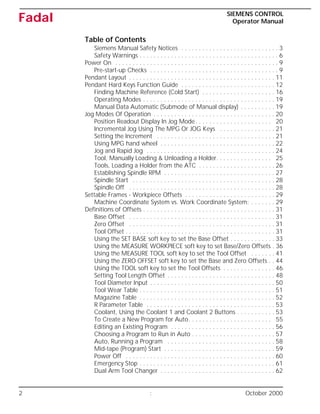
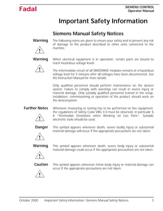

The Siemens Control Operator Manual for Fadal provides detailed operational guidance, safety notices, and maintenance instructions for the machinery. It outlines essential safety warnings, pre-startup checks, operational modes, tool handling, and emergency protocols to ensure safe and efficient use. The manual emphasizes the importance of using qualified personnel for maintenance and adhering to safety regulations to prevent accidents and equipment damage.