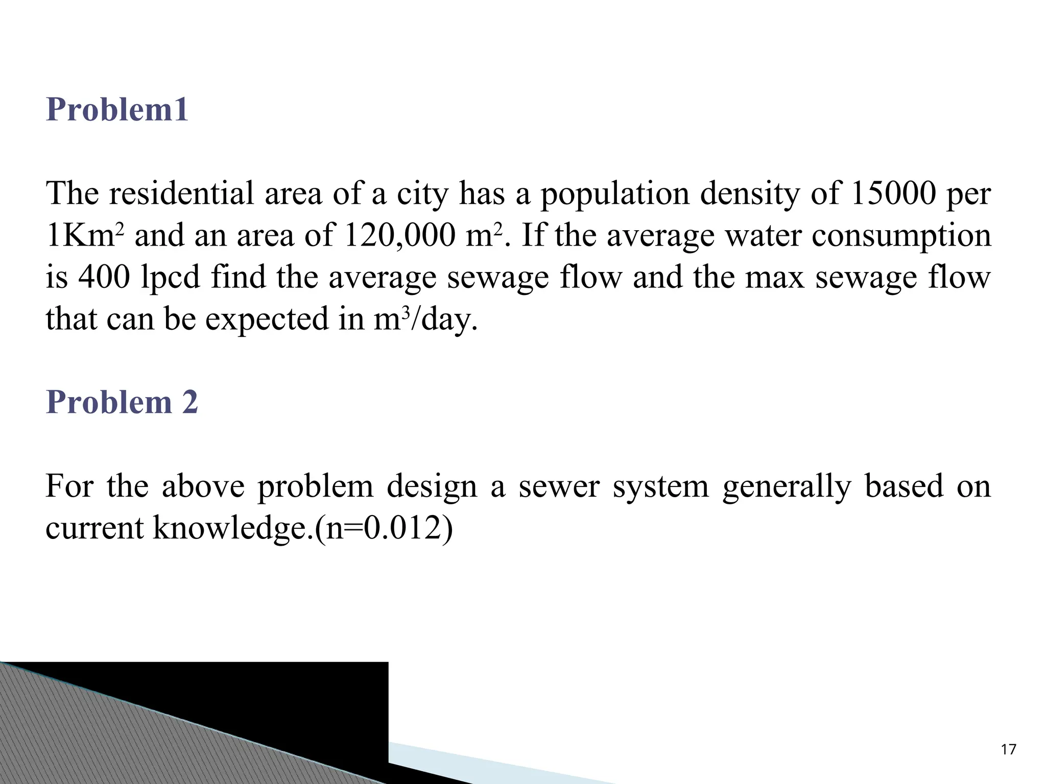
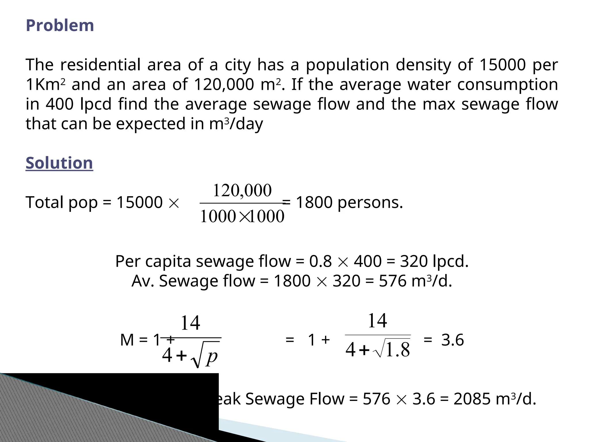
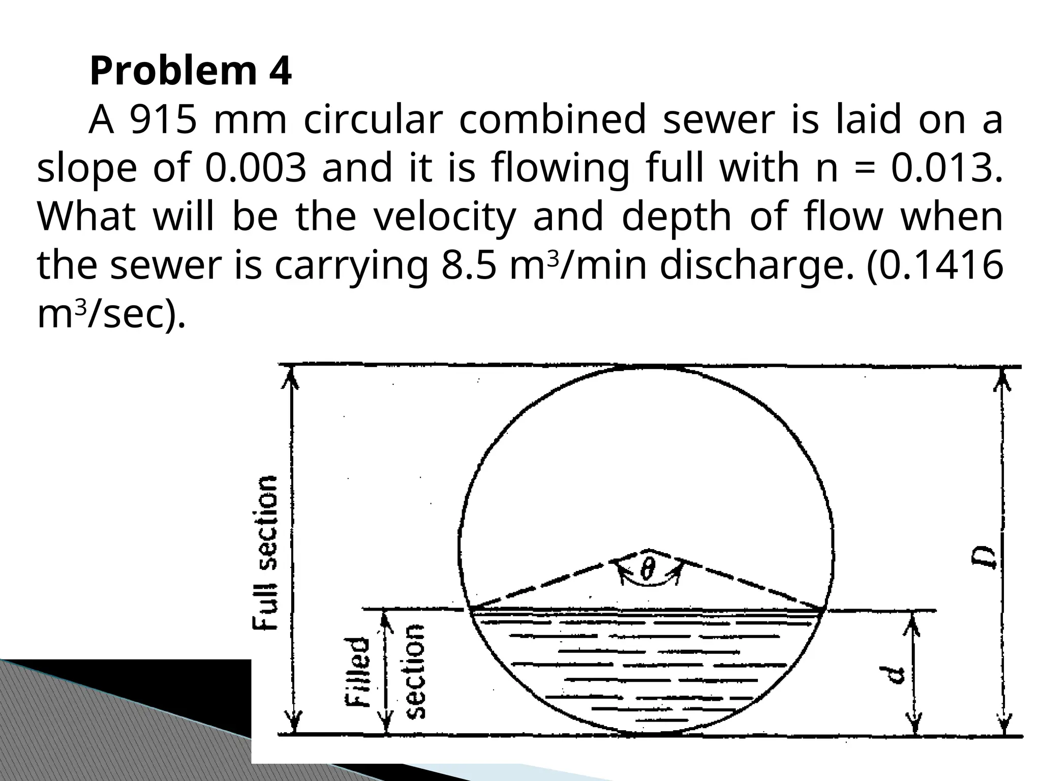
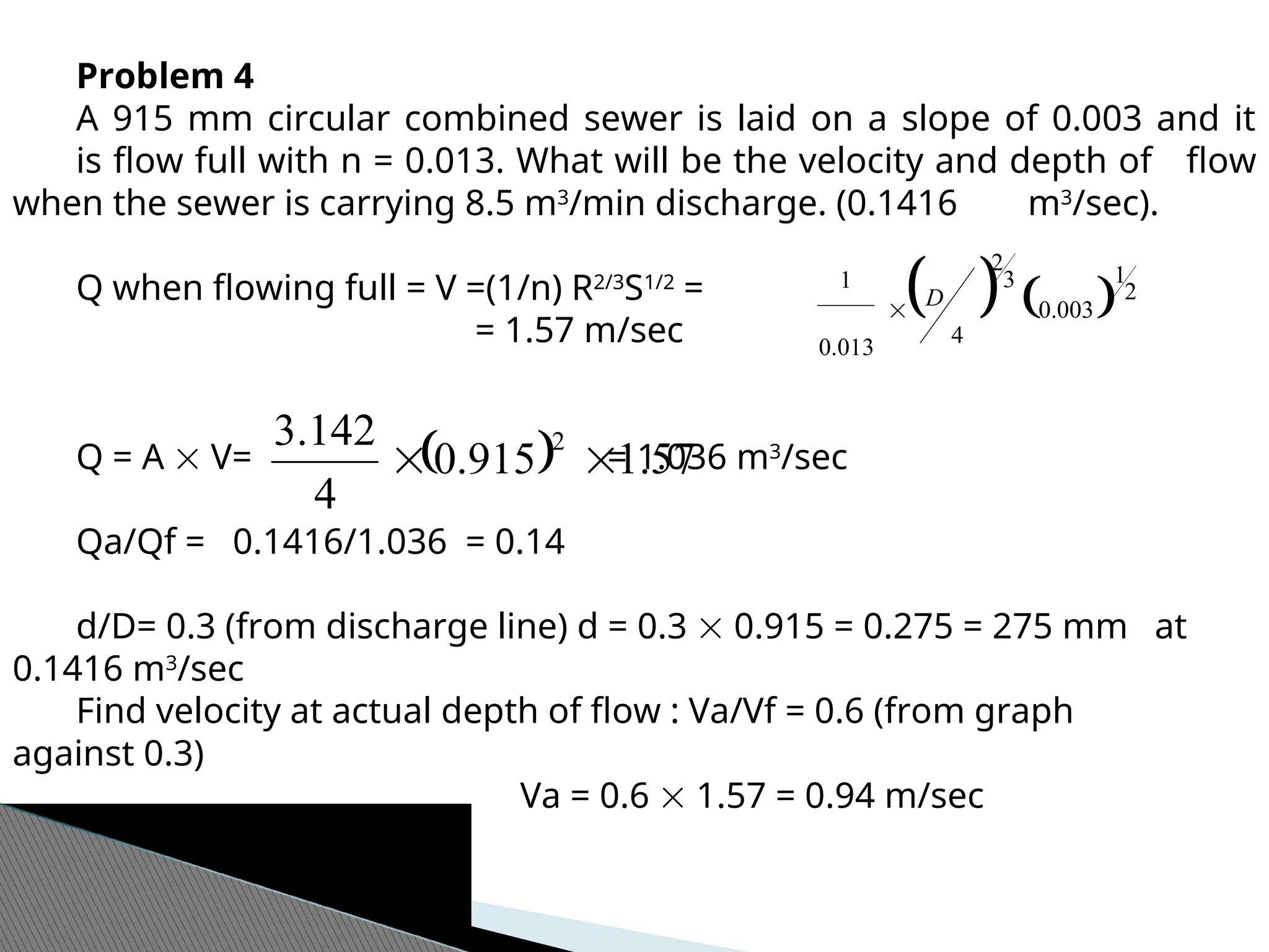
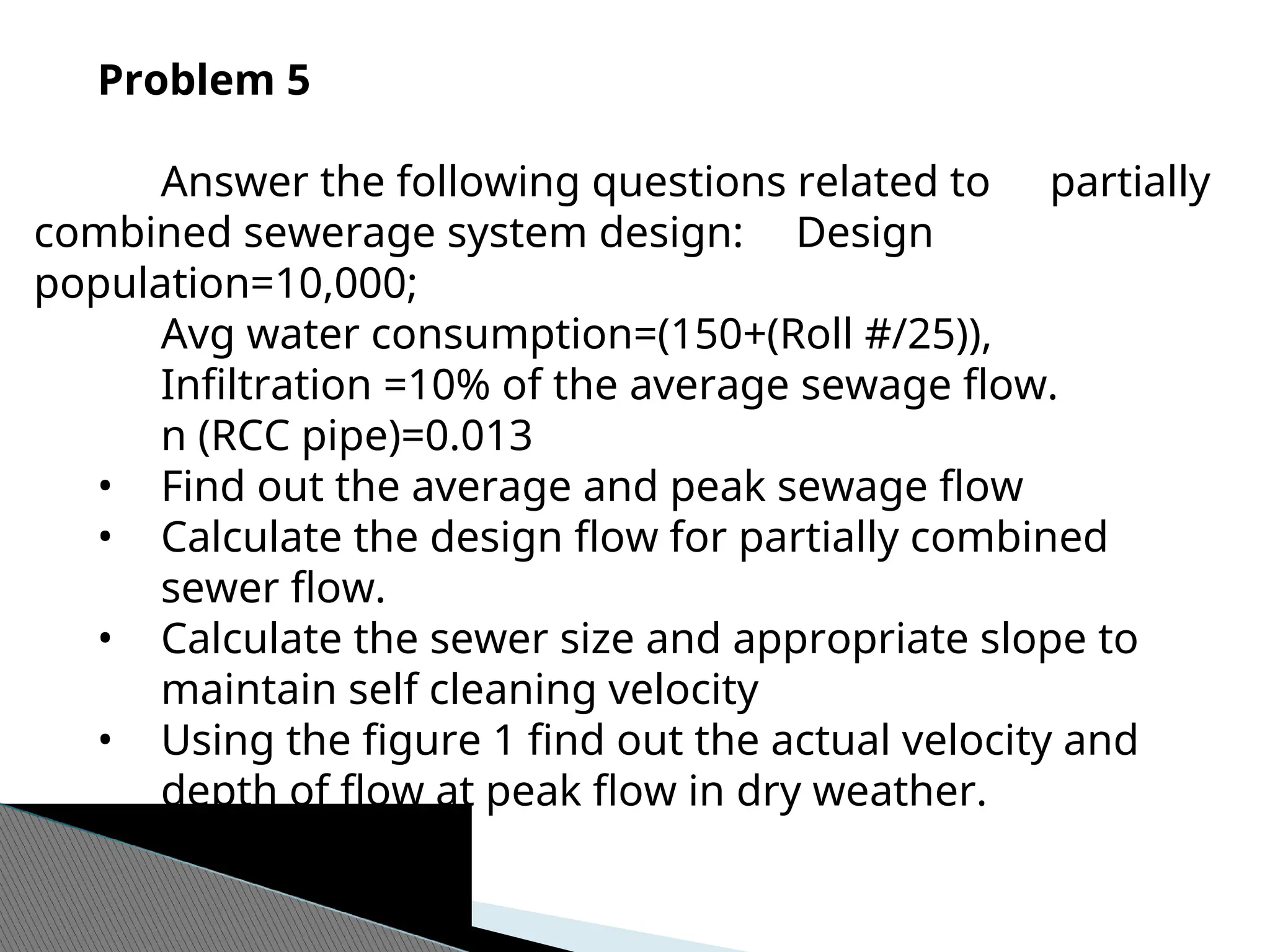
The document outlines a civil engineering course focused on wastewater collection and treatment systems, including design principles and environmental impacts. It covers various types of sewage systems, design calculations, and practical applications, emphasizing the importance of attendance, individual work, and integrity in assessments. Key components include understanding wastewater sources, sewer types, and their design requirements to ensure effective management of sewage and stormwater.


![21
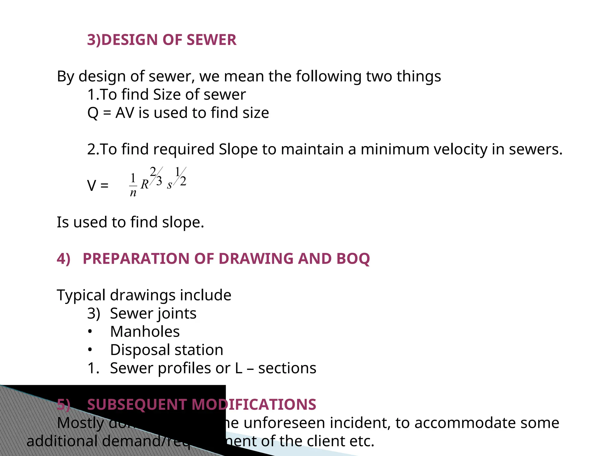
(ii) Design Equation
Sewers are designed on the basis of open channel flow.
V = (Manning’s Formula)
Where
V = Velocity, m/sec
R = hydraulic mean depth =
= D/4, when pipe is flowing full or ½ full
S = slope of sewer
n = Co-efficient of roughness for pipe (0.012 for R.C.C pipes)
(see table 15.1 EW steel for more n values)
(iii) Minimum Velocities
Min velocities also called self cleansing velocities must be maintained
in sewers to avoid deposition of suspended solids and subsequent choking
of sewers.
Sanitary sewers = 0.6 m/sec [organic particle sp. gs = 1.61]
Storm sewers = 1 m/sec [inorganic particle sp. gs = 2.65]
Partially combined = 0.7 m/sec.
2
1
3
2
1
s
R
n
perimeter
wetted
Area](https://image.slidesharecdn.com/module-3introductiondesignofsanitarysewers-250203163655-047c04cd/75/Module-3-Introduction-Design-of-Sanitary-Sewers-ppt-21-2048.jpg)
![(iv) Maximum Velocities
2.4 m/sec (E.W Steel)
A limit on higher velocity is imposed due to abrasive character of solids
in wastewater
Scraping or wearing away.
(v) Min. Sewer Size
225 mm is taken as min sever size. [WASA, PHED]
why: choaking takes place with bigger size particles/substances
which are usually thrown into sewer through manholes etc.
[Examples: shrubs, bricks etc].
(vi) Min Cover:
1m is taken as min cover over sewers to avoid damage from live loads
coming on sewers.
(vii) Manholes
Purpose
Cleaning
Inspection
House connections](https://image.slidesharecdn.com/module-3introductiondesignofsanitarysewers-250203163655-047c04cd/75/Module-3-Introduction-Design-of-Sanitary-Sewers-ppt-22-2048.jpg)
![Where provided
1.At every change in direction
2.Where two different dia pipes are to be connected.
Spacing
225 mm – 350 mm spacing 100 m
460 mm – 760 mm spacing 120 m [WASA]
> 760 mm spacing 150 m
Note For plots, one manhole be provided for 2 plots
viii)Qd/Qf Ratios
WASA recommend the Qd/Qf ratios in order to provide air space in the
upper portion of sewers for ventilation purpose. Qd represent design
flow and Qf is flow when sewer is flowing full.
Sewer Size Ratio (Qd/Qf)
225 – 380 mm 0.7
460 – 1220 mm 0.75
1370 mm and larger 0.8](https://image.slidesharecdn.com/module-3introductiondesignofsanitarysewers-250203163655-047c04cd/75/Module-3-Introduction-Design-of-Sanitary-Sewers-ppt-23-2048.jpg)


![Pollution.ppt [Autosaved].ppt yogesh kumbhar](https://cdn.slidesharecdn.com/ss_thumbnails/pollution-251205194856-d30cfee8-thumbnail.jpg?width=640&height=640&fit=bounds)


