Sewer Appurtenances
In asewerage system along with pipe lines a number of other structures /devices installations are
essential. These devices are provided for proper inspection, operation, maintenance and is termed as
sewer appurtenances. Manholes; Drop manhole Inlets; Oil and Grease Traps; inverted siphon; Pumping
Stations
Manhole: Manhole is the most important structure used in sewerage system. It is made either of
masonry or R.C.C. Chamber constructed at suitable intervals along the sewer lines, for providing access
into them. Thus, the manhole helps in inspection, cleaning and maintenance of sewer. These are provided
at every bend, junction, change of gradient or change of diameter of the sewer and at fixed interval of
100 to 150 m . The sewer line between the two manholes is laid straight with even gradient. For straight
sewer line manholes are provided at regular interval depending upon the diameter of the sewer. It
provide access to sewers for inspection and cleaning purposes.The minimum width of the manhole
should not be less than internal diameter of the sewer pipe plus 150 mm benching on both the sides.
2.
Manhole
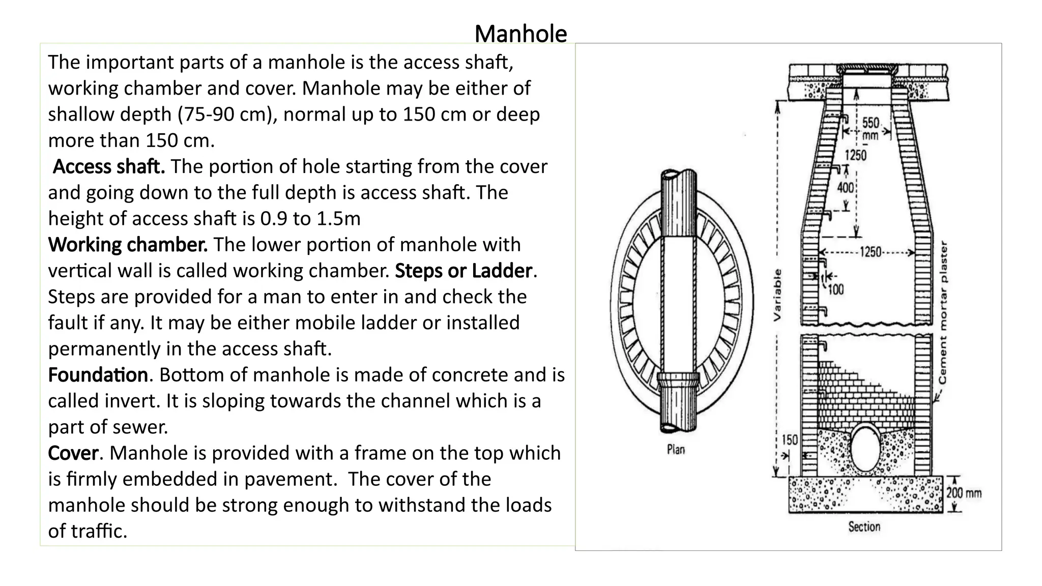
The important partsof a manhole is the access shaft,
working chamber and cover. Manhole may be either of
shallow depth (75-90 cm), normal up to 150 cm or deep
more than 150 cm.
Access shaft. The portion of hole starting from the cover
and going down to the full depth is access shaft. The
height of access shaft is 0.9 to 1.5m
Working chamber. The lower portion of manhole with
vertical wall is called working chamber. Steps or Ladder.
Steps are provided for a man to enter in and check the
fault if any. It may be either mobile ladder or installed
permanently in the access shaft.
Foundation. Bottom of manhole is made of concrete and is
called invert. It is sloping towards the channel which is a
part of sewer.
Cover. Manhole is provided with a frame on the top which
is firmly embedded in pavement. The cover of the
manhole should be strong enough to withstand the loads
of traffic.
3.
Drop Manhole
Drop manhole.A manhole constructed to provide a
connection between two sewers when the
difference of elevation between the two pipes is ≥
60 cm. The drop manhole has a vertical pipe to
prevent turbulence in the manhole and to allow
the maintenance works to enter the manholes
safely. It avoids un necessary steep gradient of
and thus save a large quantity of earth work. Drop
manhole can be inspected horizontally like a
manhole.
4.
Grease and oiltraps
From institutions, commercial units, restaurants,
dwellings and other places which discharge oil
and grease in their effluent, a grease and oil trap
should be used to remove it before they enter
the sewage pipes. Grease and oil affect the
sewers and treatment plant equipment's that is
why they should be removed. In case of the
pipes, grease sticks to the walls and collects sand
and other solids leading eventually to the
decrease in the pipe diameter and some times to
complete clogging.
5.
Inverted Siphon
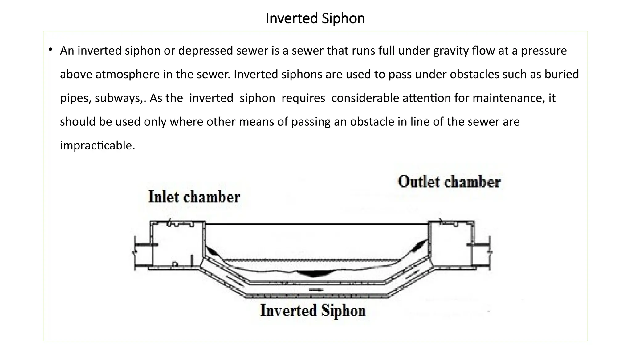
• Aninverted siphon or depressed sewer is a sewer that runs full under gravity flow at a pressure
above atmosphere in the sewer. Inverted siphons are used to pass under obstacles such as buried
pipes, subways,. As the inverted siphon requires considerable attention for maintenance, it
should be used only where other means of passing an obstacle in line of the sewer are
impracticable.
6.
Lamp Hole
It isan opening or hole constructed in a sewer for purpose of lowering a lamp inside it. It
consists of stoneware or concrete pipe, which is connected to sewer line through a T-junction.
The pipe is covered with concrete to make it stable. Manhole cover of sufficient strength is
provided at ground level to take the load of traffic. An electric lamp is inserted in the lamp hole
and the light of lamp is observed from manholes. If the sewer length is unobstructed, the
light of lamp will be seen. It is constructed when construction of manhole is difficult. In
present practice as far as possible the use of lamp hole is avoided. This lamp hole can also be
used for flushing the sewers. If the top cover is perforated it will also help in ventilating the
sewer, such lamp hole is known as fresh air inlet.
7.
STORMWATER INLETS
Storm waterinlets are provided to admit the surface runoff to the sewers. These are classified in three
major groups viz. curb inlets, gutter inlets, and combined inlets. They are provided either depressed or
uniform slope flush with respect to the elevation of the pavement surface. The structure of the inlet is
constructed with brickwork with cast iron grating at the opening. Where the traffic load is not expected,
fabricated steel grating can be used. The clear opening shall not be more than 25 mm. The connecting
pipe from the street inlet to the sewer should be minimum of 200 mm diameter and laid with sufficient
slope. A maximum spacing of 30 m is recommended between the inlets, which depends upon the road
surface, size and type of inlet and rainfall.
•
8.
Catch Basins
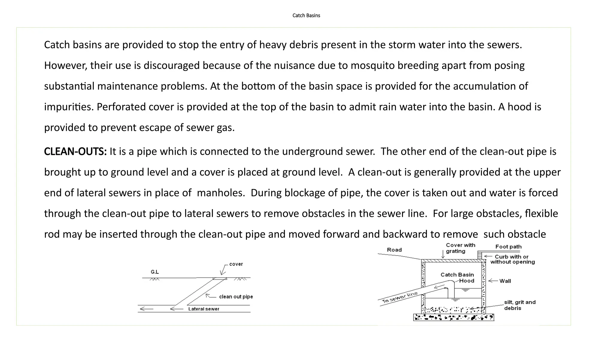
Catch basinsare provided to stop the entry of heavy debris present in the storm water into the sewers.
However, their use is discouraged because of the nuisance due to mosquito breeding apart from posing
substantial maintenance problems. At the bottom of the basin space is provided for the accumulation of
impurities. Perforated cover is provided at the top of the basin to admit rain water into the basin. A hood is
provided to prevent escape of sewer gas.
CLEAN-OUTS: It is a pipe which is connected to the underground sewer. The other end of the clean-out pipe is
brought up to ground level and a cover is placed at ground level. A clean-out is generally provided at the upper
end of lateral sewers in place of manholes. During blockage of pipe, the cover is taken out and water is forced
through the clean-out pipe to lateral sewers to remove obstacles in the sewer line. For large obstacles, flexible
rod may be inserted through the clean-out pipe and moved forward and backward to remove such obstacle
9.
SEWAGE PUMPING STATIONS
Theseare required to elevate and transport wastewater when Continuation of gravity flow is no
longer feasible due to any obstacle lies in the path of sewer (e.g. river, canal etc) and/or
receiving stream is higher than the sewer.
Pumps for Sewage:
Centrifugal, single suction, non-clogging type pumps are normally used. They have impellers
Having two or three vanes. Pump suction pipe is usually larger than the discharge pipe by about
25%. Smallest discharge pipe =75mm ,while smallest suction pipe =100 mm.
Components of Sewage Pumping Station
Screens: To screen out large floating matters which can damage the pumps
Dry well: To house the pump and Wet well: for receipt of wastewater.
Following are the general design considerations of sewage pumping stations.
i. More than one pump should be provided to cope with variable discharge. Two pumps for small
Pumping Station and more than two for large Pumping Station should be used.
10.
GENERAL DESIGN CONSIDERATIONS
ii.Total pumping capacity of the Pumping Station must be equal to the peak sewage flow.
iii. Standby pump must be provided at the Pumping Station. Its capacity should be at least 50% of peak
sewage flow.
iv. Alternate source of power must be provided at Pumping Station (Either power from two feeders or a
diesel operated pump be provided)
v. Pumps should be self priming(self evacuating) and should operate under +ve suction head.
vi.Each pump should have an individual intake.
vii. Screens with 50 mm opening be provided at pump suction to avoid entrance of big particles in pumps.
viii.Size of dry well should be sufficient to house pumping machinery.
ix. Dry well be provided with pumps which are usually RECIPROCATING PUMPS to pump out sewage leaks
in dry well.
x. Sluice valves must be provided at suction and non-return valve at the delivery side.
xi. Detention time in wet well should not be greater than 30 minutes to avoid septic conditions.
11.
GENERAL DESIGN CONSIDERATIONS
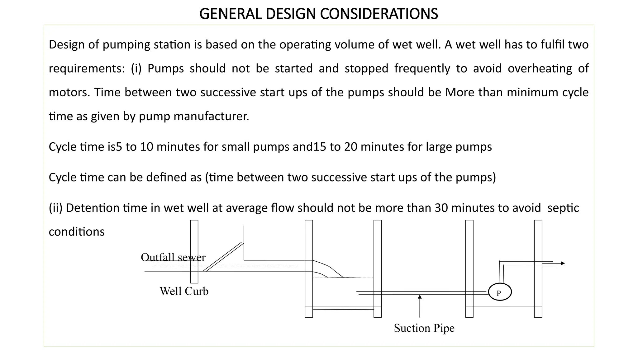
Designof pumping station is based on the operating volume of wet well. A wet well has to fulfil two
requirements: (i) Pumps should not be started and stopped frequently to avoid overheating of
motors. Time between two successive start ups of the pumps should be More than minimum cycle
time as given by pump manufacturer.
Cycle time is5 to 10 minutes for small pumps and15 to 20 minutes for large pumps
Cycle time can be defined as (time between two successive start ups of the pumps)
(ii) Detention time in wet well at average flow should not be more than 30 minutes to avoid septic
conditions
P
Suction Pipe
Well Curb
Outfall sewer


![Sewer appurtenances [recovered]](https://cdn.slidesharecdn.com/ss_thumbnails/sewerappurtenancesrecovered-180318135220-thumbnail.jpg?width=640&height=640&fit=bounds)


