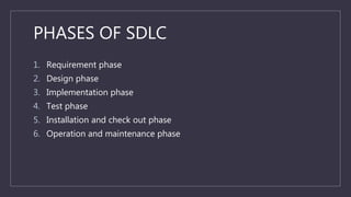
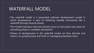
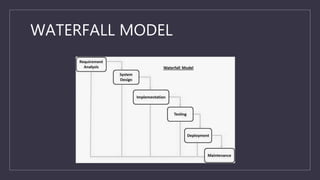
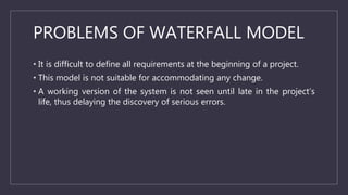
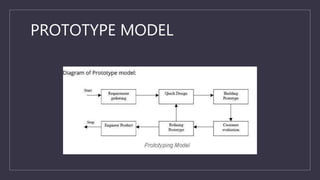
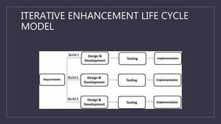
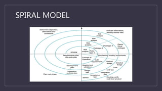
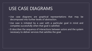
C
SOFTWARE
DEVELOPMENT LIFE
CYCLE (SDLC)
DEFINITION
• A software life cycle is often called as a software development life cycle
and it is a particular abstraction that represents a software life cycle.
• The period of time that starts when a software product is conceived and
ends when the product is no longer available for use.
PHASES OF SDLC
1. Requirement phase
2. Design phase
3. Implementation phase
4. Test phase
5. Installation and check out phase
6. Operation and maintenance phase
BUILD AND FIX MODEL
• Sometimes, a product is constructed without specification. Basically, this
is an adhoc approach and not well defined.
• It is a simple two phase model.
• The first phase is to write code and the next phase is to fix it.
• Fixing in this context may be error correction or addition of further
functionality.
WATERFALL MODEL
• The waterfall model is a sequential software development model in
which development is seen as following steadily downwards like a
waterfall through several phases.
• This model maintains that one should move to next phase only when its
preceding phase is complete and perfect.
• Phases of development in the waterfall model are thus discrete and
there is no jumping back and forth or overlapping between them.
WATERFALL MODEL
PROBLEMS OF WATERFALL MODEL
• It is difficult to define all requirements at the beginning of a project.
• This model is not suitable for accommodating any change.
• A working version of the system is not seen until late in the project’s
life, thus delaying the discovery of serious errors.
PROTOTYPE MODEL
• Here, we first develop a working prototype of the software instead of
developing the actual software.
PROTOTYPE MODEL
ADVANTAGES OF PROTOTYPE MODEL
• Users are actively involved in the development.
• It provides better system to users, as users have natural tendency to
change their mind in specifying requirements.
• Since, in this methodology, a working model of the system is provided
to the users so that they can get a better understanding of the system
being developed.
• Errors can be detected much earlier as the system is made side by side.
• Quick user feedback is available leading to better solution.
DISADVANTAGES OF PROTOTYPE
MODEL
• Practically, this methodology may increase the complexity of the system
as scope of the system may expand beyond original plans.
• This model leads to implementing and then repairing way of building
system.
ITERATIVE ENHANCEMENT LIFE CYCLE
MODEL
• This model counters the limitation of the waterfall model and combines
the benefits of both prototyping and the waterfall models.
• The basic idea is that the software should be developed in increments,
where each increment adds some functional capability to the system
until the full system is implemented.
• At each step extensions and design modifications can be made.
• An advantage of this approach is that it can result in better testing,
since testing each increment is likely to be easier than testing entire
system like in the waterfall model.
ITERATIVE ENHANCEMENT LIFE CYCLE
MODEL
SPIRAL MODEL
• This is the recent model that has been proposed by Barry Boehm.
• The spiral model has many cycles.
• The radial dimension represents the cumulative cost incurred in
accomplishing the steps done so far and the angular dimension
represents the progress made in completing each cycle of spiral.
• The spiral model is divided into a number of framework activities called
task regions.
SPIRAL MODEL
TASK REGIONS IN SPIRAL MODEL
1. CUSTOMER COMMUNICATION: Task required to establish effective
communication between developer and customer.
2. PLANNING: Task required to define resources, timeliness and other
project related information.
3. RISK ANALYSIS: Task required to access both technical and
management risks.
4. ENGINEERING: Task required to build one or more representations of
the application.
TASK REGIONS IN SPIRAL MODEL
5. CONSTRUCTION AND RELEASE: Task required to construct, test,
install and provide user support.
6. CUSTOMER EVALUATION: Task required to obtain customer
feedback based on evaluation of the software representations
created during the engineering stage and implemented during the
installation stage.
SOFTWARE REQUIREMENTS
• Software requirement is a process to understand the exact
requirements of the customer and to document them properly.
• The hardest part of building a software system is deciding precisely
what to build.
ANALYSIS & SPECIFICATIONS
• Requirements describe the “what” of a system not the “how”.
• Requirements engineering produces one large document, contains a
description of what the system will do.
REQUIREMENT ELICITATION
• This is also known as gathering of requirements.
• Here, requirements are identified with the help of customer and existing
system processes, if available.
METHODS IN REQUIREMENT
ELICITATION
1. INTERVIEWS: First step to understand the problem statement of
customer, i.e., meeting with customer.
2. BRAINSTORMING SESSIONS: It is a kind of group discussion which
may lead to new ideas quickly and help to promote creative thinking.
3. FACILITATED APPLICATION SPECIFICATION TECHNIQUE (FAST): The
objective of FAST approach is to bridge the expectation gap, a
difference between what developers think they are supposed to build
and what customers think they are going to get.
METHODS IN REQUIRMENT
ELICITATION
4. THE USE CASE APPROACH: This approach uses a combination of text
and pictures in order to improve the understanding of requirements.
USE CASE DIAGRAMS
• Use case diagrams are graphical representations that may be
decomposed into further levels of abstraction.
• Use case is initiated by a user with a particular goal in mind and
competes successfully when that goal is satisfied.
• It describes the sequence of interactions between actors and the system
necessary to deliver services that satisfies the goal.
REQUIREMENT ANALYSIS
• Requirement analysis allows the system analyst to refine the software
allocation and build conceptual models of the data, functional and
behavioural domains that will be treated by software.
DATA MODELING
• Define data objects attributes and relationships.
• We use E-R diagrams for this purpose.
BEHAVIOURAL MODELING
• Finding out different states of the system.
• Specifying events that cause the system to change state.
• We use state transition diagrams for behavioural modelling.
FUNCTION MODELING
• Identify functions that transform data objects.
• Indicate how data flows through system.
• Represent producers and consumers of data.
REQUIREMENT DOCUMENTATION
• Requirement document is the way to represent requirements in a
consistent format.
• Requirement document is called SRS, i.e., Software Requirements
Specification.
• The SRS should be correct, unambiguous, complete, consistent,
verifiable, modifiable, traceable.
KEY POINTS
• For function modelling, we use Data Flow Diagrams (DFDs). DFD shows
the flow of data through a system.
• The requirement review process is carried out to improve the quality of
the SRS.
• The requirement review process may also be called as requirements
verification.
• For maximum benefits, review and verification should not be treated as
a discrete activity to be done only at the end of preparation of SRS. It
should be treated as continuous activity that is incorporated into the
elicitation, analysis and documentation.

Software development life cycle (SDLC)

  • 1.
  • 2.
    DEFINITION • A softwarelife cycle is often called as a software development life cycle and it is a particular abstraction that represents a software life cycle. • The period of time that starts when a software product is conceived and ends when the product is no longer available for use.
  • 3.
    PHASES OF SDLC 1.Requirement phase 2. Design phase 3. Implementation phase 4. Test phase 5. Installation and check out phase 6. Operation and maintenance phase
  • 4.
    BUILD AND FIXMODEL • Sometimes, a product is constructed without specification. Basically, this is an adhoc approach and not well defined. • It is a simple two phase model. • The first phase is to write code and the next phase is to fix it. • Fixing in this context may be error correction or addition of further functionality.
  • 5.
    WATERFALL MODEL • Thewaterfall model is a sequential software development model in which development is seen as following steadily downwards like a waterfall through several phases. • This model maintains that one should move to next phase only when its preceding phase is complete and perfect. • Phases of development in the waterfall model are thus discrete and there is no jumping back and forth or overlapping between them.
  • 6.
  • 7.
    PROBLEMS OF WATERFALLMODEL • It is difficult to define all requirements at the beginning of a project. • This model is not suitable for accommodating any change. • A working version of the system is not seen until late in the project’s life, thus delaying the discovery of serious errors.
  • 8.
    PROTOTYPE MODEL • Here,we first develop a working prototype of the software instead of developing the actual software.
  • 9.
  • 10.
    ADVANTAGES OF PROTOTYPEMODEL • Users are actively involved in the development. • It provides better system to users, as users have natural tendency to change their mind in specifying requirements. • Since, in this methodology, a working model of the system is provided to the users so that they can get a better understanding of the system being developed. • Errors can be detected much earlier as the system is made side by side. • Quick user feedback is available leading to better solution.
  • 11.
    DISADVANTAGES OF PROTOTYPE MODEL •Practically, this methodology may increase the complexity of the system as scope of the system may expand beyond original plans. • This model leads to implementing and then repairing way of building system.
  • 12.
    ITERATIVE ENHANCEMENT LIFECYCLE MODEL • This model counters the limitation of the waterfall model and combines the benefits of both prototyping and the waterfall models. • The basic idea is that the software should be developed in increments, where each increment adds some functional capability to the system until the full system is implemented. • At each step extensions and design modifications can be made. • An advantage of this approach is that it can result in better testing, since testing each increment is likely to be easier than testing entire system like in the waterfall model.
  • 13.
  • 14.
    SPIRAL MODEL • Thisis the recent model that has been proposed by Barry Boehm. • The spiral model has many cycles. • The radial dimension represents the cumulative cost incurred in accomplishing the steps done so far and the angular dimension represents the progress made in completing each cycle of spiral. • The spiral model is divided into a number of framework activities called task regions.
  • 15.
  • 16.
    TASK REGIONS INSPIRAL MODEL 1. CUSTOMER COMMUNICATION: Task required to establish effective communication between developer and customer. 2. PLANNING: Task required to define resources, timeliness and other project related information. 3. RISK ANALYSIS: Task required to access both technical and management risks. 4. ENGINEERING: Task required to build one or more representations of the application.
  • 17.
    TASK REGIONS INSPIRAL MODEL 5. CONSTRUCTION AND RELEASE: Task required to construct, test, install and provide user support. 6. CUSTOMER EVALUATION: Task required to obtain customer feedback based on evaluation of the software representations created during the engineering stage and implemented during the installation stage.
  • 18.
    SOFTWARE REQUIREMENTS • Softwarerequirement is a process to understand the exact requirements of the customer and to document them properly. • The hardest part of building a software system is deciding precisely what to build.
  • 19.
    ANALYSIS & SPECIFICATIONS •Requirements describe the “what” of a system not the “how”. • Requirements engineering produces one large document, contains a description of what the system will do.
  • 20.
    REQUIREMENT ELICITATION • Thisis also known as gathering of requirements. • Here, requirements are identified with the help of customer and existing system processes, if available.
  • 21.
    METHODS IN REQUIREMENT ELICITATION 1.INTERVIEWS: First step to understand the problem statement of customer, i.e., meeting with customer. 2. BRAINSTORMING SESSIONS: It is a kind of group discussion which may lead to new ideas quickly and help to promote creative thinking. 3. FACILITATED APPLICATION SPECIFICATION TECHNIQUE (FAST): The objective of FAST approach is to bridge the expectation gap, a difference between what developers think they are supposed to build and what customers think they are going to get.
  • 22.
    METHODS IN REQUIRMENT ELICITATION 4.THE USE CASE APPROACH: This approach uses a combination of text and pictures in order to improve the understanding of requirements.
  • 23.
    USE CASE DIAGRAMS •Use case diagrams are graphical representations that may be decomposed into further levels of abstraction. • Use case is initiated by a user with a particular goal in mind and competes successfully when that goal is satisfied. • It describes the sequence of interactions between actors and the system necessary to deliver services that satisfies the goal.
  • 24.
    REQUIREMENT ANALYSIS • Requirementanalysis allows the system analyst to refine the software allocation and build conceptual models of the data, functional and behavioural domains that will be treated by software.
  • 25.
    DATA MODELING • Definedata objects attributes and relationships. • We use E-R diagrams for this purpose.
  • 26.
    BEHAVIOURAL MODELING • Findingout different states of the system. • Specifying events that cause the system to change state. • We use state transition diagrams for behavioural modelling.
  • 27.
    FUNCTION MODELING • Identifyfunctions that transform data objects. • Indicate how data flows through system. • Represent producers and consumers of data.
  • 28.
    REQUIREMENT DOCUMENTATION • Requirementdocument is the way to represent requirements in a consistent format. • Requirement document is called SRS, i.e., Software Requirements Specification. • The SRS should be correct, unambiguous, complete, consistent, verifiable, modifiable, traceable.
  • 29.
    KEY POINTS • Forfunction modelling, we use Data Flow Diagrams (DFDs). DFD shows the flow of data through a system. • The requirement review process is carried out to improve the quality of the SRS. • The requirement review process may also be called as requirements verification. • For maximum benefits, review and verification should not be treated as a discrete activity to be done only at the end of preparation of SRS. It should be treated as continuous activity that is incorporated into the elicitation, analysis and documentation.