1. Manufacturers of critical devices need precision and efficiency in production to get products to market quickly amid competition. Scientific molding uses data collection and analysis to create a repeatable manufacturing process that produces defect-free parts consistently.
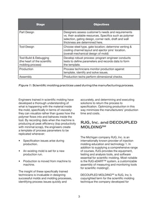
2. Scientific molding involves engineers overseeing different phases of product development and production. They collect data during tool debugging to create a template for production. This template ensures repeatability when specifications change or production moves to different machines.
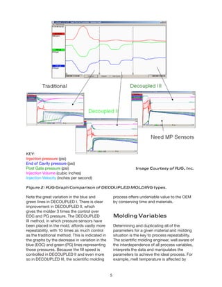
3. RJG, Inc. provides scientific molding education and tools like the eDARTTM system. Their decoupled molding techniques separate filling, packing, and holding stages to control the process more precisely, minimizing defects. Data from these