
![18
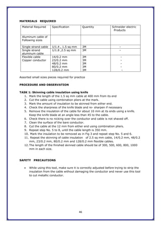
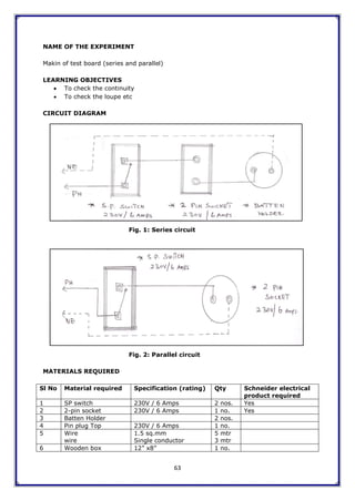
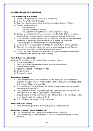
CHAPTER VII: ELECTRICAL ACCESSORIES
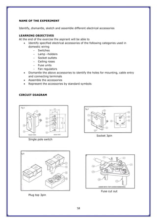
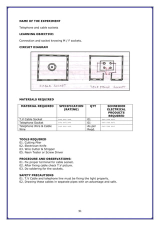
Switches, Sockets
Introduction
Electrical appliances occupy a prime place of importance in our life style. The usage of
electricity in modern life is increasing the standard of living in almost every home. On the
other hand, Electrical wiring, which is essential for these appliances to work, receives very
little attention. As an electrical technician, contractor, consultant or architect we are
responsible to both the builder and consumer. The reputation and success of technicians
depends on the quality of wiring they door recommend.
Teaching and Learning Methodology
Lecture Method, Demonstration and Site visit
Aim
To impart knowledge and related skills to the aspirant
Learning Objective
At the end of this session the aspirant will know about the:
a. Protection and distribution of supply system and accessories used
b. Cable carrier and support system
c. Different types of current carrying conductors
d. Switching and terminating products
e. Sensor switching etc.
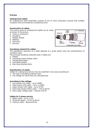
Preview
House wiring accessories can be classified into the following
categories:
a. Control and distribution system
b. Cable carrier and support system
c. Current carrying conductors (wires)
d. Switching and termination products
e. Sensor Switches
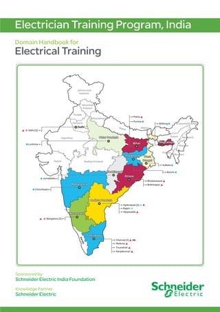
a. Control (Protection) and distribution system
This system is used to control the main supply and distribute it to the circuits. The main
protective devices used in house wiring circuits are:
i. Fuses (Fuse that can be re-wired, HRC Fuses available at diff
ranges [6Amp to 200Amp])
ii. ICDP, ICTP (available at 32A to 200A)
iii. Miniature Circuit Breakers (available at 1A to 40A)
iv. Isolator (available at 32A to 63A)
v. ELCB / RCCB – (available at 32A, 40A & 63A) and MCCB above
63A
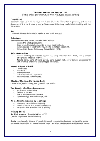
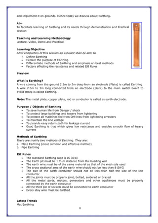
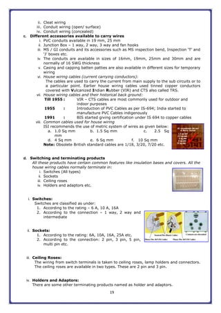
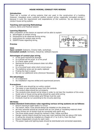
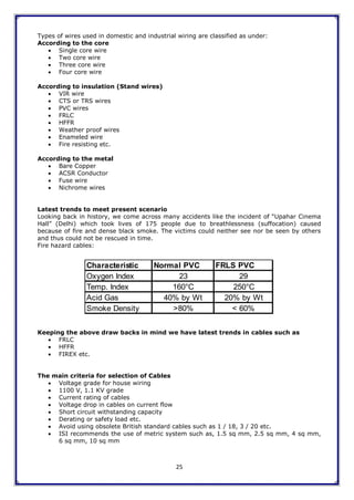
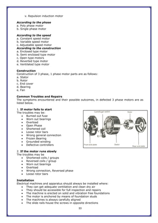
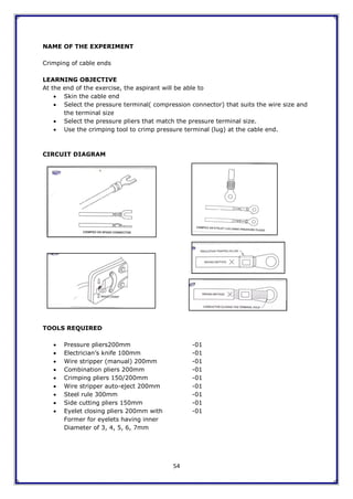
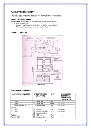
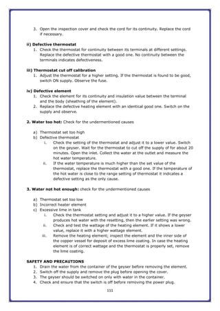
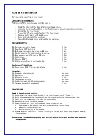
All the above mentioned items are installed in control and distribution
boards. The Boards are available in 1 phase, 3 phase, single door and
double door as shown in the picture.
b. Cable carrier and support
The house wiring cable can‟t be run or laid on walls without support.
Hence the wires need to be supported from the main distribution till
the terminating product. The systems used to carry, support and run
these wires are called cable carriers and support systems. The different
systems which we adopt for the same are as follows:
i. Wooden capping & casing wiring](https://image.slidesharecdn.com/schneiderelectricalhandbook-210216112928/85/Schneider-electrical-handbook-24-320.jpg)
![37
ii. Semi Automatic delta starter
iii. Fully automatic delta starter
3. Auto: Transformer type starter
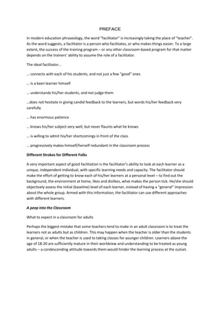
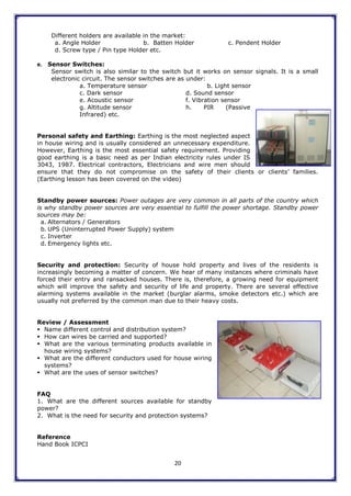
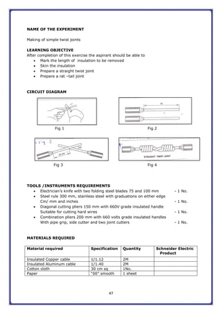
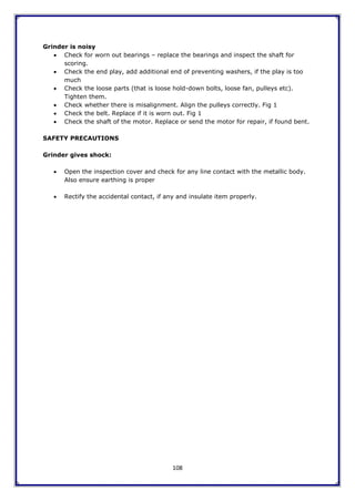
1. Direct Online (DOL) Starter
It is a simple and ordinary starter, suitable for squirrel cage induction motors that have a
capacity up to 5 HP. It does not reduce the voltage. It is sufficient to connect the motor from
the line ICTP / Main switch / Isolator. The DOL starter has the following advantages:
a. The motor can be switched on and off quickly.
b. It cuts the motor from the line one over loads.
c. It prevents the motor from burning on single phase.
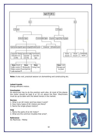
Mainly DOL starters consist of contact system thermal relay units and a solenoid coils.
The contact system consists of silver tipped contacts, which provides a quick on – off
system.
Thermal relay bimetallic elements protect the motor from over load.
The solenoid coil or no–volt coil is connected across the two phases. (Phase and
neutral in case of single phase)
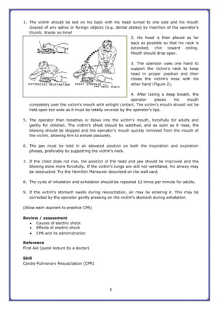
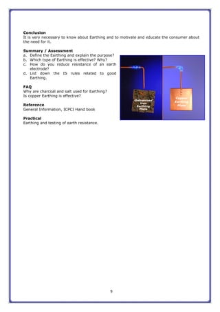
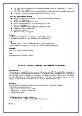
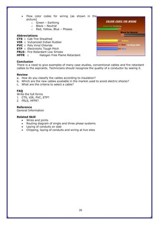
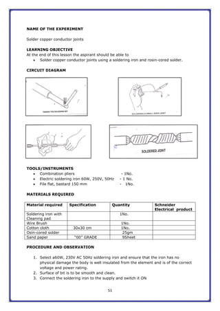
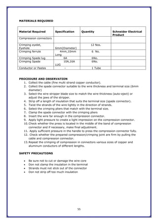
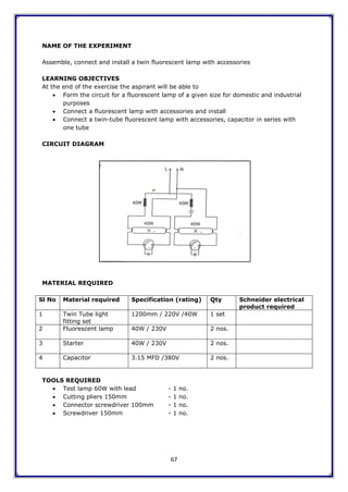
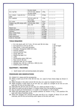
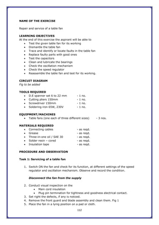
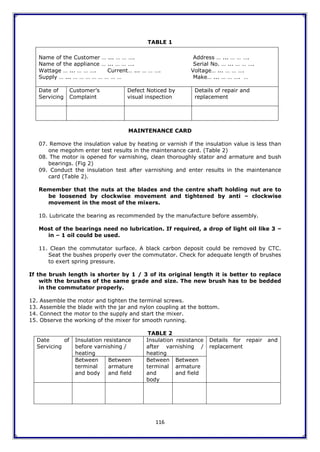
On pressing the start button the solenoid coil becomes magnetized and it attracts the
iron, plunger, which closes all the contact points.
In this way L1, L2 and L3 are connected to the motor terminals M1, M2 and M3 and
the motor starts running, as shown in the picture above.
Push buttons are used in place of the handles. The green push button starts the motor, while
the red push button switches off the motor. A latch fitted near the red push button can be
adjusted over it, so that motor may not be started.
Protective Devices
No–Volt Coil (NVC) and Over Load coil Relay (OLR) are provided in a start delta starter as
protective devices.
No–Volt Coil (NVC) [Ref Figure given below]
It is an electromagnetic coil made of fine copper wire. The NVC is connected to B2 and A2
terminals. These terminals get supply from L1 to L3 respectively in the run position. If the
supply fails, the motor becomes over loaded, then the NVC will be demagnetized and will
release the handle, thus the motor will be switched off.
Over–Load Relay
It consists of three bi-metallic strips, which get bent in one direction, above a pre-set
temperature. The bending of these strips disconnects the NVC, which will leave the hands of](https://image.slidesharecdn.com/schneiderelectricalhandbook-210216112928/85/Schneider-electrical-handbook-43-320.jpg)

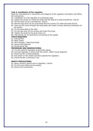
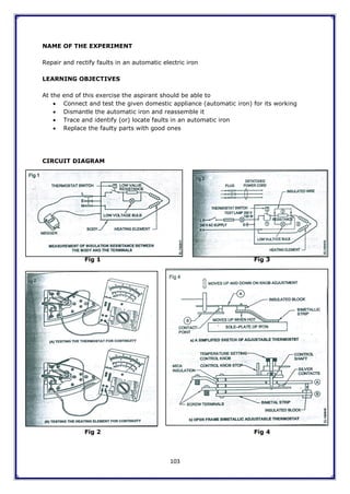
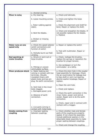


Electric fires can be caused by short circuits, overloading, poor insulation, or lightning. Fires are classified based on the type of fuel source - Class A for solids, Class B for liquids, Class C for gases, and Class D for metals. The right type of fire extinguisher must be used for each class of fire, such as dry chemical powder or CO2 extinguishers for electrical fires, in order to effectively put out the fire.


