Downloaded 139 times
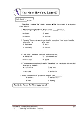
![CONSUMER ELECTRONICS SERVICING 49
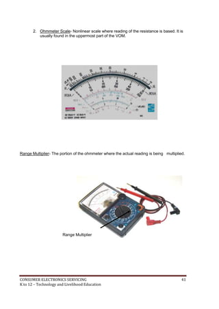
K to 12 – Technology and Livelihood Education
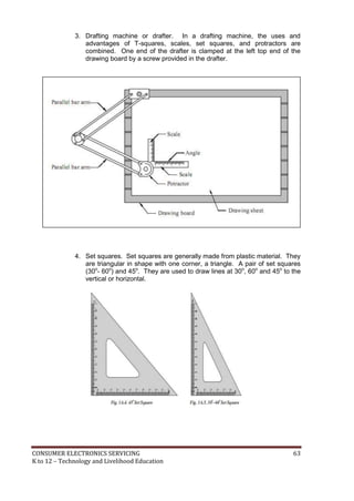
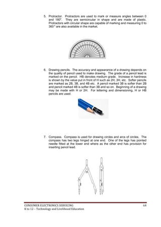
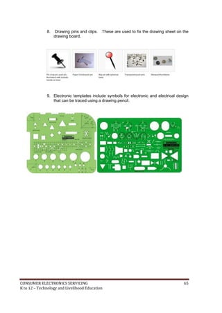
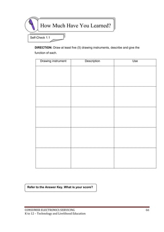
What Do You Need To Know?
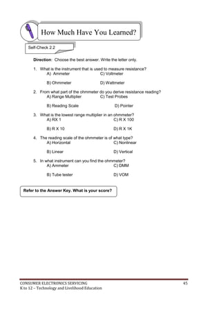
4. Place instruments in a cool dry place and away from any
____________devices.
A) Audio amplifiers C) Magnetic devices
B) Other instruments D) Digital sources
5. What measuring instrument should be given regular check up by connecting it
to power line?
A) Capacitor Tester C) Oscilloscope
B) DMM D) VOM
]
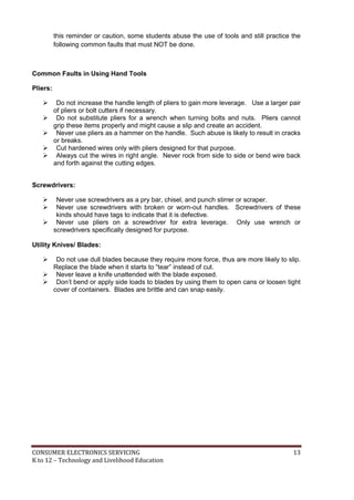
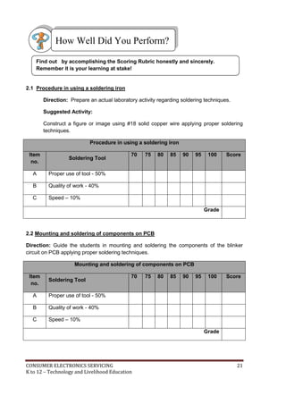
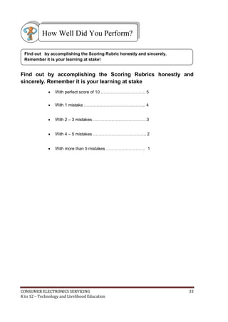
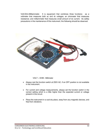
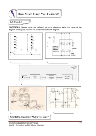
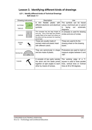
Measuring instruments in electronics are confined only to analog testers and
sometimes digital millimeter. Either way the maintenance of these instruments is a
priority in all electronics laboratory rooms.
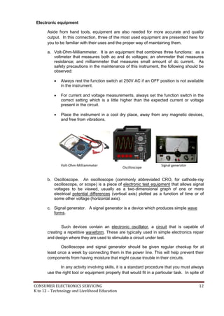
Electronic Measuring Instruments
Aside from hand tools, measuring instruments are also needed for more
accurate and quality output. In this connection, three of the most used instruments
are presented here for you to be familiar with their uses and the proper way of
maintaining them.
Information Sheet 3.1
Read Information Sheet 3.1 very well then find out how much you can remember
and how much you learned by doing Self-check.](https://image.slidesharecdn.com/kto12electronicslearningmodule-130822014516-phpapp02-151126145518-lva1-app6892/85/K-to-12-Electronics-Learning-Module-50-320.jpg)

![CONSUMER ELECTRONICS SERVICING 94
K to 12 – Technology and Livelihood Education
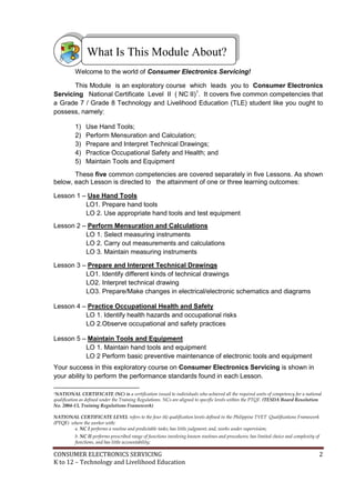
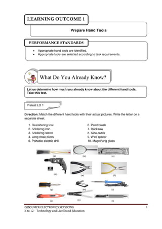
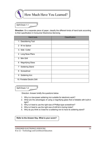
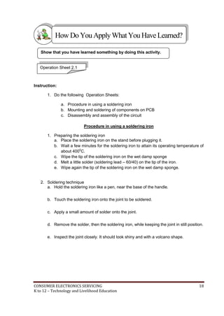
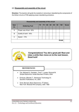
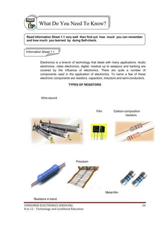
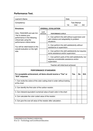
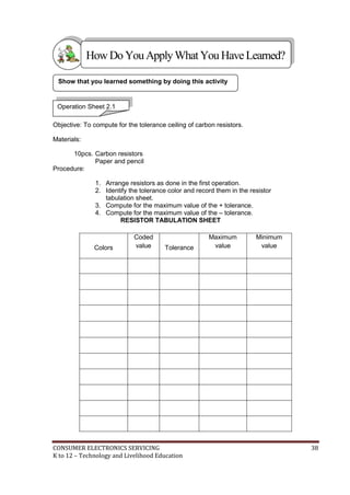
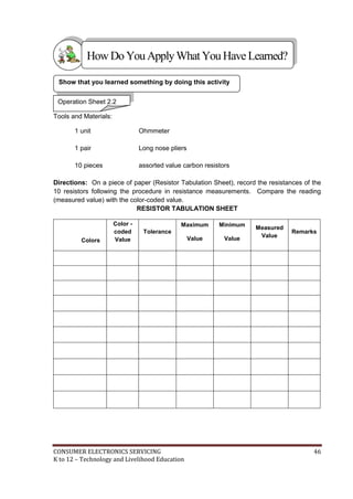
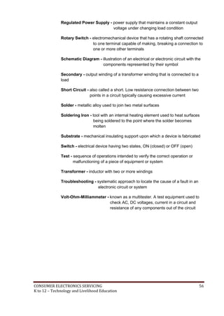
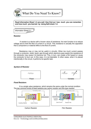
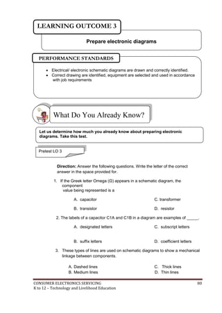
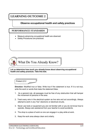
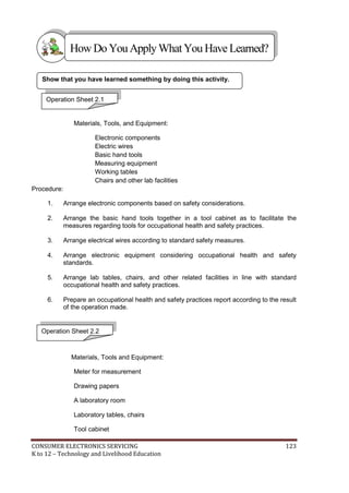
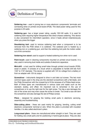
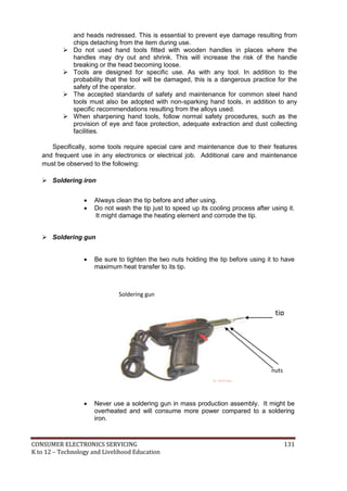
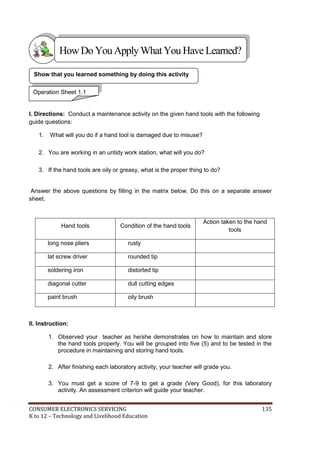
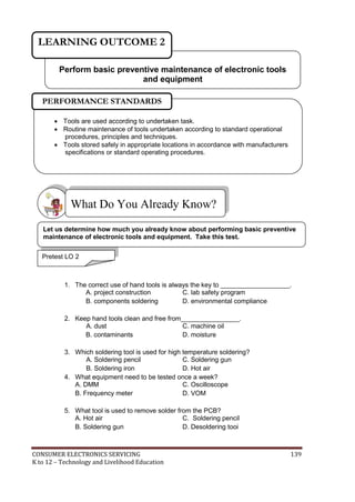
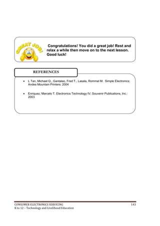
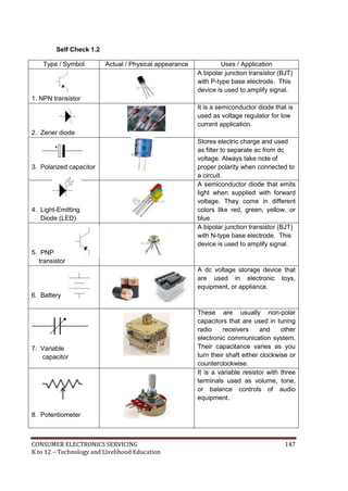
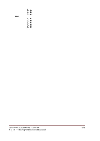
Observation Checklist
Students name:
Teachers name:
Name of School
Competency
standards
Unit of competency:
Instructions for the teacher:
1. Observe the student [insert description of activity being observed].
2. Describe the assessment activity and the date in which it was undertaken.
3. Place a tick in the box to show that the student completed each aspect of the activity in
accordance to the standard expected in the enterprise.
4. Complete the feedback sections of the form.
Date of observation
Description of assessment
activity
Location of assessment activity
The Student…… If yes, tick the box
Did the student overall performance meet the standard? Yes No
Feedback to student
Teachers signature: Date:](https://image.slidesharecdn.com/kto12electronicslearningmodule-130822014516-phpapp02-151126145518-lva1-app6892/85/K-to-12-Electronics-Learning-Module-95-320.jpg)
![CONSUMER ELECTRONICS SERVICING 95
K to 12 – Technology and Livelihood Education
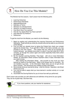
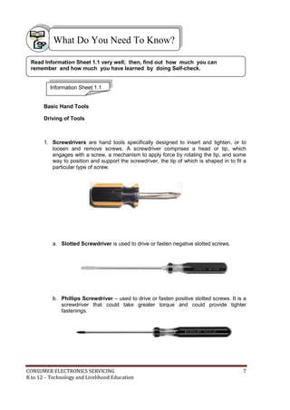
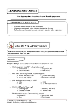
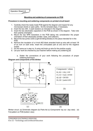
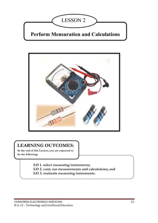
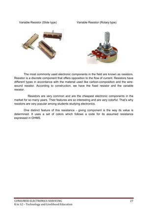
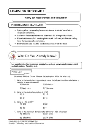
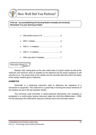
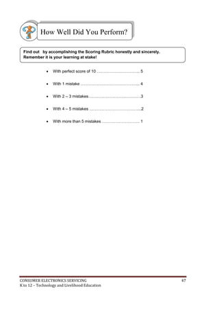
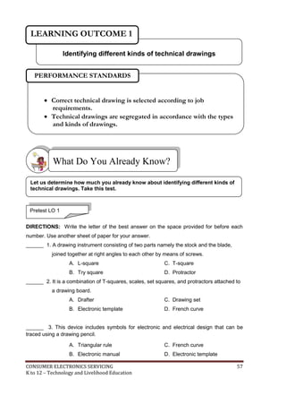
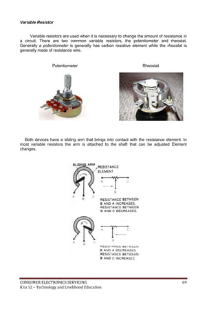
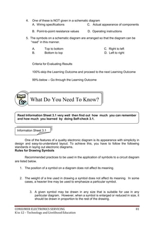
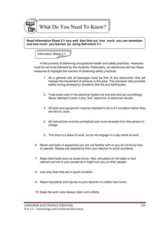
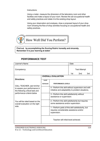
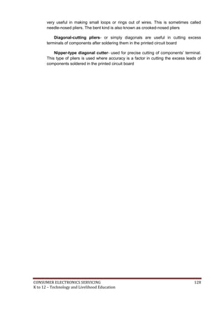
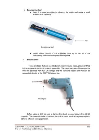
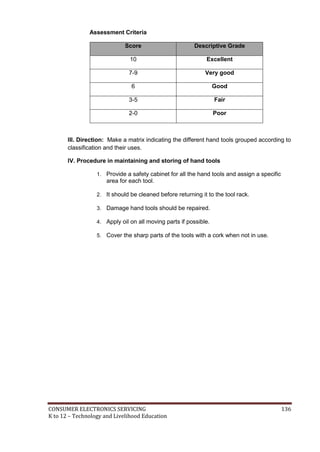
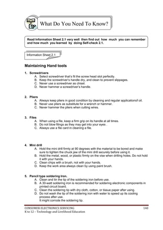
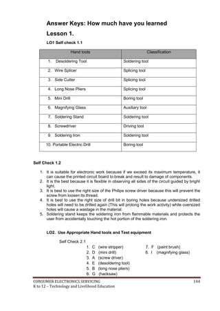
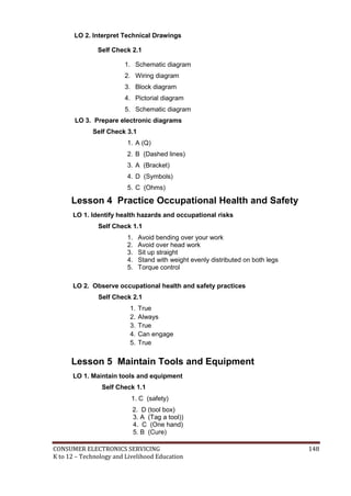
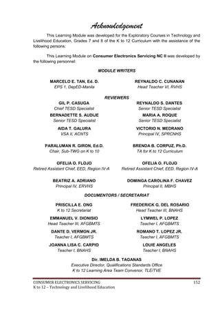
Observation and Questioning Checklist
Student’s name:
Teacher’s name:
Assessment Center
Competency
standards
Unit of competency:
Instructions for the teacher:
1. Observe the student [insert description of activity being observed].
2. Describe the assessment activity and the date on which it was undertaken.
3. Place a tick in the box to show that the student completed each aspect of the activity in
accordance to the standard expected in the enterprise.
4. Ask the student a selection of the questions from the attached list to confirm his/her
underpinning knowledge.
5. Place a tick in the box to show that the student answered the questions correctly.
6. Complete the feedback sections of the form.
Date of observation
Description of assessment
activity
Location of assessment
activity
The student…. If yes, tick the box
can
Did the student’s overall performance meet the standard? Yes No](https://image.slidesharecdn.com/kto12electronicslearningmodule-130822014516-phpapp02-151126145518-lva1-app6892/85/K-to-12-Electronics-Learning-Module-96-320.jpg)
![CONSUMER ELECTRONICS SERVICING 99
K to 12 – Technology and Livelihood Education
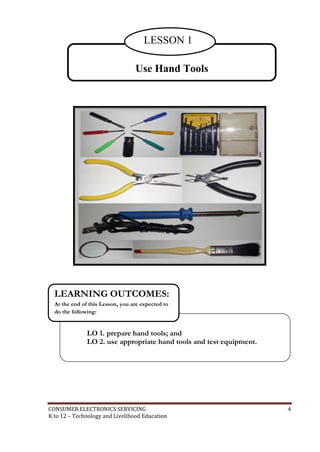
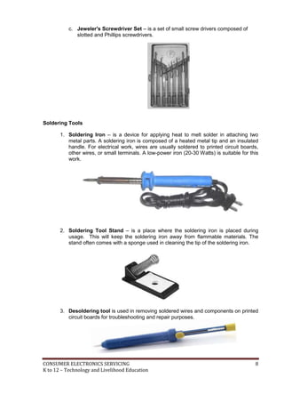
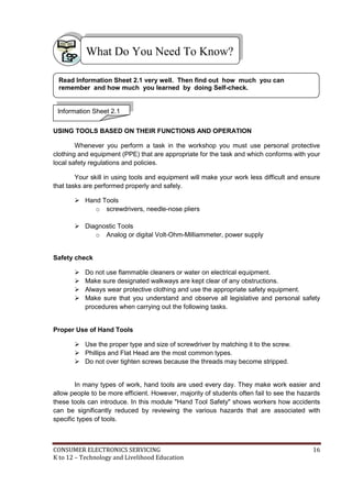
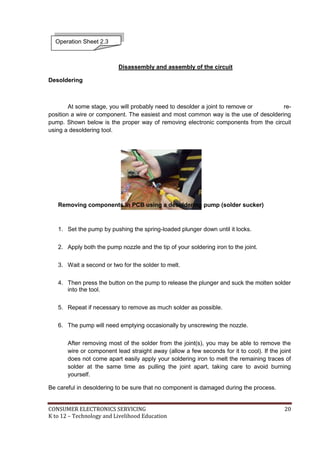
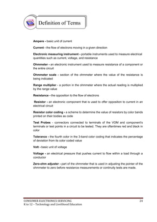
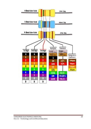
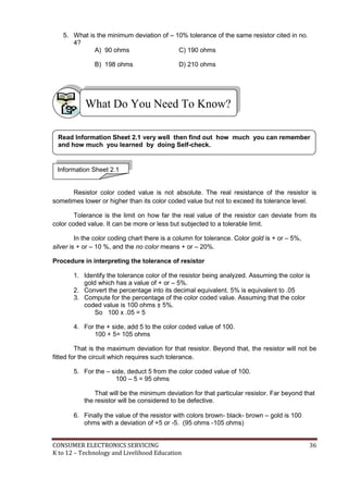
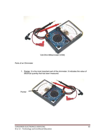
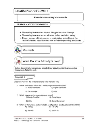
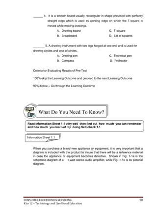
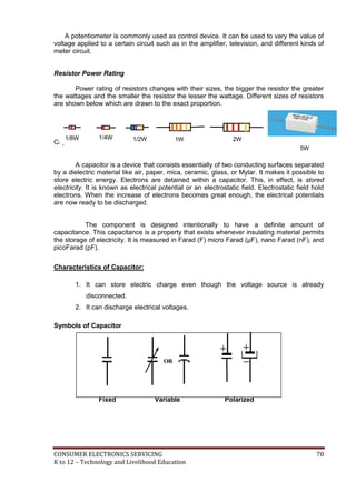
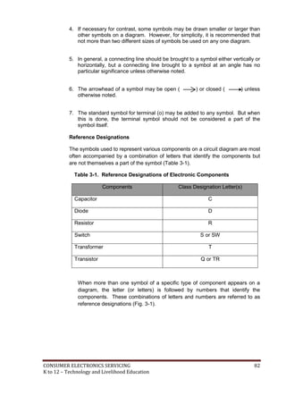
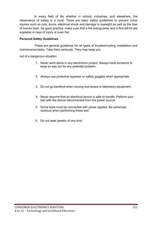
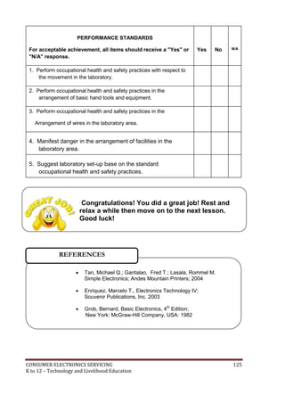
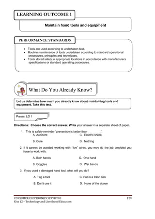
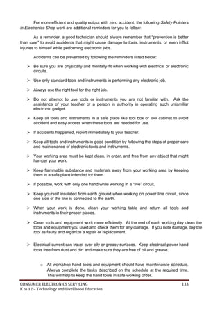
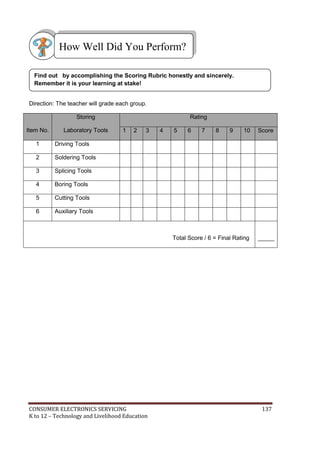
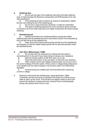
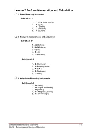
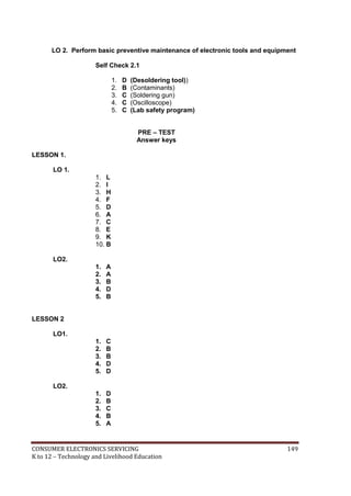
Written report
Student’s name:
Teacher’s name:
Assessment Center
Competency
standards
Unit of competency:
Task:
Your task is to:
[insert description of task]
Submission date:
Use the checklist below as a basis for judging whether the student’s report meets the
required competency standards.
The student’s report…. If yes, tick the box
can solve quantities needed through percentage
can tabulate data correctly
can convert temperature to the required temperature scale
can fill in appropriate form completely and correctly
can identify proper method of sealing packed products
can label correctly packed products
Overall did the student’s report meet the standard? Yes No
Comments:
Student’s
signature:
Date:
Teacher’s
signature:
Date:](https://image.slidesharecdn.com/kto12electronicslearningmodule-130822014516-phpapp02-151126145518-lva1-app6892/85/K-to-12-Electronics-Learning-Module-100-320.jpg)
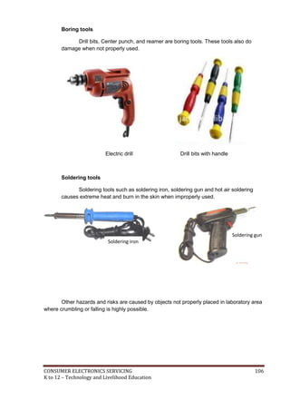
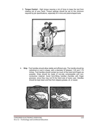
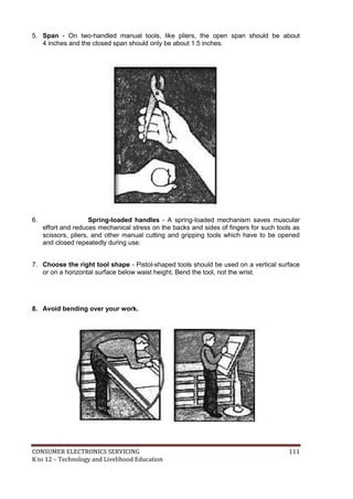
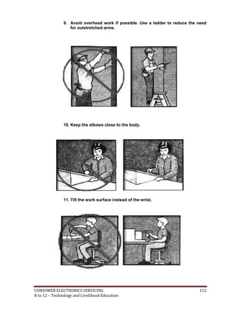
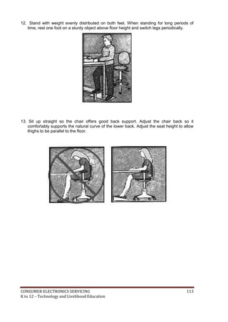

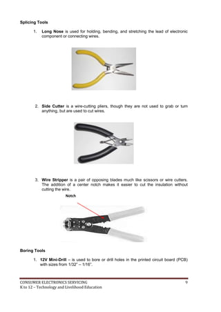
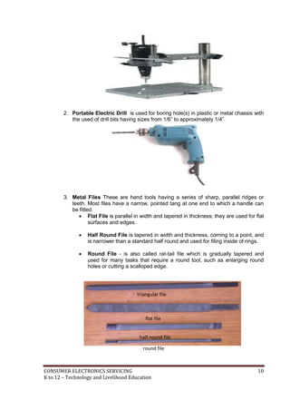
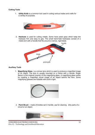
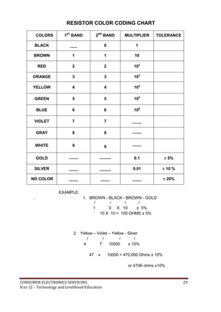
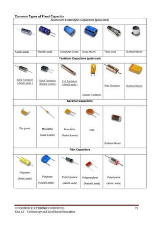
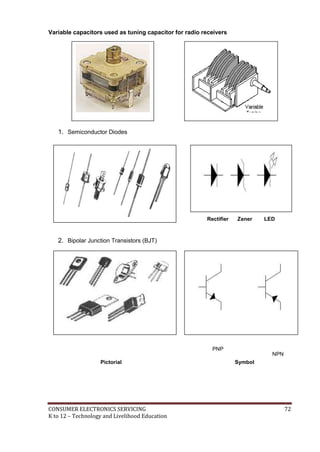
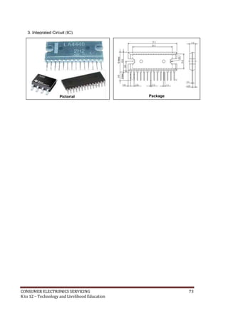
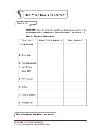
The document provides guidance on using various hand tools for consumer electronics servicing, including screwdrivers, soldering tools, splicing tools, drilling tools, cutting tools, and auxiliary tools. It also covers safety precautions and common faults to avoid when using hand tools. The document is meant to teach students in grades 7 and 8 the basic skills needed for consumer electronics servicing.