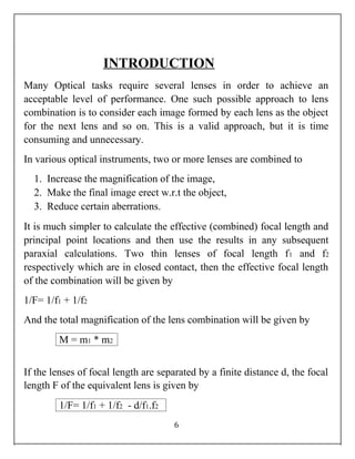
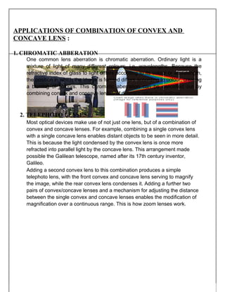
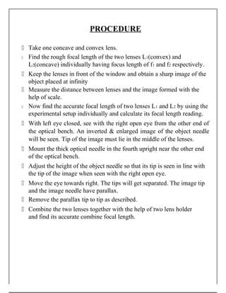
JAWAHAR NAVODAYA VIDYALAYA
VADNAGAR , MEHSANA
A PROJECT REPORT SUBMITTED TO
PHYSICS DEPARTMENT
By :- Sahil Chauhan
Class :- XII sci.
Year :- 2017-18
Guided by :- Mr. B.L.Kumawat
Certificate
This is to certify that Ma./Ku.: SAHIL CHAUHAN.
A student of class XII of the school jawahar navodaya
vidyalaya,vadnagar. Roll No.1214 Session 2017-18
has satisfactorily completed the required chemistry
project work as per the syllabus of standard XII in
the laboratory of the school.
B.L.KUMAWAT
Date:-____________ (P.G.T. PHYSICS)
External examiner’s signature:-
ACKNOWLEDGEMENT
I wish to express my deep gratitude and sincere thanks to our
physics teacher B.L.Kumawat for her invaluable guidance,
constant encouragement, constructive, comments, sympathetic
attitude and immense motivation, which has sustained my efforts at
all stages of this project work. Her valuable advice and suggestions
for the corrections, modifications and improvement did enhance
the perfection in performing my job well.
I would like to express my gratitude for our honorable principal
Dr.VIJAY KUMAR for whole hearted co-operation& guidance. I
am also thankful for her encouragement and for all the facilities that
she provided for this project work. I sincerely appreciate this
magnanimity by taking me into her fold for which I shall remain
indebted to her.
3
Table of content
 Aim
 Introduction
 Requirements
 Procedure
 Observations
 Calculations
 Precautions
 Sources Of Errors
 Bibliography
 Conclusion
AIM
To determine the combined focal length of one Concave and
one convex lenses separated by a finite distance
INTRODUCTION
Many Optical tasks require several lenses in order to achieve an
acceptable level of performance. One such possible approach to lens
combination is to consider each image formed by each lens as the object
for the next lens and so on. This is a valid approach, but it is time
consuming and unnecessary.
In various optical instruments, two or more lenses are combined to
1. Increase the magnification of the image,
2. Make the final image erect w.r.t the object,
3. Reduce certain aberrations.
It is much simpler to calculate the effective (combined) focal length and
principal point locations and then use the results in any subsequent
paraxial calculations. Two thin lenses of focal length f1 and f2
respectively which are in closed contact, then the effective focal length
of the combination will be given by
1/F= 1/f1 + 1/f2
And the total magnification of the lens combination will be given by
M = m1 * m2
If the lenses of focal length are separated by a finite distance d, the focal
length F of the equivalent lens is given by
1/F= 1/f1 + 1/f2 - d/f1.f2
6
APPLICATIONS OF COMBINATION OF CONVEX AND
CONCAVE LENS :
1. CHROMATIC ABBERATION
One common lens aberration is chromatic aberration. Ordinary light is a
mixture of light of many different colours, i.e. wavelengths. Because the
refractive index of glass to light differs according to its colour or wavelength,
the position in which the image is formed differs according to colour, creating
a blurring of colours. This chromatic aberration can be cancelled out by
combining convex and concave lenses of different refractive indices.
2. TELEPHOTO LENSES
Most optical devices make use of not just one lens, but of a combination of
convex and concave lenses. For example, combining a single convex lens
with a single concave lens enables distant objects to be seen in more detail.
This is because the light condensed by the convex lens is once more
refracted into parallel light by the concave lens. This arrangement made
possible the Galilean telescope, named after its 17th century inventor,
Galileo.
Adding a second convex lens to this combination produces a simple
telephoto lens, with the front convex and concave lens serving to magnify
the image, while the rear convex lens condenses it. Adding a further two
pairs of convex/concave lenses and a mechanism for adjusting the distance
between the single convex and concave lenses enables the modification of
magnification over a continuous range. This is how zoom lenses work.
REQUIREMENTS
 An optical bench with three uprights (central upright fixed, two
outer uprights with lateral movement)
 One convex lens
 One Concave lens
 Two lens holder
 Two optical needles
 Half metre scale
PROCEDURE
 Take one concave and convex lens.
 Find the rough focal length of the two lenses L1(convex) and
L2(concave) individually having focus length of f1 and f2 respectively.
 Keep the lenses in front of the window and obtain a sharp image of the
object placed at infinity
 Measure the distance between lenses and the image formed with the
help of scale.
 Now find the accurate focal length of two lenses L1 and L2 by using the
experimental setup individually and calculate its focal length reading.
 With left eye closed, see with the right open eye from the other end of
the optical bench. An inverted & enlarged image of the object needle
will be seen. Tip of the image must lie in the middle of the lenses.
 Mount the thick optical needle in the fourth upright near the other end
of the optical bench.
 Adjust the height of the object needle so that its tip is seen in line with
the tip of the image when seen with the right open eye.
 Move the eye towards right. The tips will get separated. The image tip
and the image needle have parallax.
 Remove the parallax tip to tip as described.
 Combine the two lenses together with the help of two lens holder
and find its accurate combine focal length.
OBSERVATIONS
The separation between the two convex lenses = 7.2 cm
CALCULATIONS
1/F = 1/f1 + 1/f2 - d/f1f2
= 1/10 + 1/(-9) - 7.2/(10)(-9)
= -1/90 + 7.2/90
1/F=6.2/90
F = 90/6.2 cm
Therefore, F = 14.516 cm
Serial Lenses Rough Radius of f=R/2
no. focal curvature(R) (cm)
length(cm)
1. Convex(L1) 9.5 20 10
2. Concave(L2) 8 18 -9
PRECAUTIONS
 Tips of the object and image needles should lie at the same height
as the centre of the lens.
 Parallax should be removed from tip to tip by keeping eye at a
distance at least 30cm away from the needle.
 The object needle should be placed at such a distance that only real,
inverted image of it is formed.
SOURCES OF ERROR
 The uprights may not be the vertical.
 Parallax removal may not be perfect.
BIBLOGRAPHY
 Comprehensive Pratical Physics Class XII
 NCERT Physics Part – II
 Experimental Physics
 www.wikipedia.com
CONCLUSION
The combined focal length of one convex and one
concave lenses having focal length 10 cm and 9cm
respectively and separated by a distance of 7.2 cm is
14.516 cm.
2.So on combination of the one convex and one concave
lens the effective focal length increases and hence its
effective power decreases.
3.The effective nature of the combined lens system is
converging i.e. convex lens since focal length for the
system comes out to be positive.
combination of lanses

combination of lanses

  • 1.
    JAWAHAR NAVODAYA VIDYALAYA VADNAGAR, MEHSANA A PROJECT REPORT SUBMITTED TO PHYSICS DEPARTMENT By :- Sahil Chauhan Class :- XII sci. Year :- 2017-18 Guided by :- Mr. B.L.Kumawat
  • 2.
    Certificate This is tocertify that Ma./Ku.: SAHIL CHAUHAN. A student of class XII of the school jawahar navodaya vidyalaya,vadnagar. Roll No.1214 Session 2017-18 has satisfactorily completed the required chemistry project work as per the syllabus of standard XII in the laboratory of the school. B.L.KUMAWAT Date:-____________ (P.G.T. PHYSICS) External examiner’s signature:-
  • 3.
    ACKNOWLEDGEMENT I wish toexpress my deep gratitude and sincere thanks to our physics teacher B.L.Kumawat for her invaluable guidance, constant encouragement, constructive, comments, sympathetic attitude and immense motivation, which has sustained my efforts at all stages of this project work. Her valuable advice and suggestions for the corrections, modifications and improvement did enhance the perfection in performing my job well. I would like to express my gratitude for our honorable principal Dr.VIJAY KUMAR for whole hearted co-operation& guidance. I am also thankful for her encouragement and for all the facilities that she provided for this project work. I sincerely appreciate this magnanimity by taking me into her fold for which I shall remain indebted to her. 3
  • 4.
    Table of content Aim  Introduction  Requirements  Procedure  Observations  Calculations  Precautions  Sources Of Errors  Bibliography  Conclusion
  • 5.
    AIM To determine thecombined focal length of one Concave and one convex lenses separated by a finite distance
  • 6.
    INTRODUCTION Many Optical tasksrequire several lenses in order to achieve an acceptable level of performance. One such possible approach to lens combination is to consider each image formed by each lens as the object for the next lens and so on. This is a valid approach, but it is time consuming and unnecessary. In various optical instruments, two or more lenses are combined to 1. Increase the magnification of the image, 2. Make the final image erect w.r.t the object, 3. Reduce certain aberrations. It is much simpler to calculate the effective (combined) focal length and principal point locations and then use the results in any subsequent paraxial calculations. Two thin lenses of focal length f1 and f2 respectively which are in closed contact, then the effective focal length of the combination will be given by 1/F= 1/f1 + 1/f2 And the total magnification of the lens combination will be given by M = m1 * m2 If the lenses of focal length are separated by a finite distance d, the focal length F of the equivalent lens is given by 1/F= 1/f1 + 1/f2 - d/f1.f2 6
  • 7.
    APPLICATIONS OF COMBINATIONOF CONVEX AND CONCAVE LENS : 1. CHROMATIC ABBERATION One common lens aberration is chromatic aberration. Ordinary light is a mixture of light of many different colours, i.e. wavelengths. Because the refractive index of glass to light differs according to its colour or wavelength, the position in which the image is formed differs according to colour, creating a blurring of colours. This chromatic aberration can be cancelled out by combining convex and concave lenses of different refractive indices. 2. TELEPHOTO LENSES Most optical devices make use of not just one lens, but of a combination of convex and concave lenses. For example, combining a single convex lens with a single concave lens enables distant objects to be seen in more detail. This is because the light condensed by the convex lens is once more refracted into parallel light by the concave lens. This arrangement made possible the Galilean telescope, named after its 17th century inventor, Galileo. Adding a second convex lens to this combination produces a simple telephoto lens, with the front convex and concave lens serving to magnify the image, while the rear convex lens condenses it. Adding a further two pairs of convex/concave lenses and a mechanism for adjusting the distance between the single convex and concave lenses enables the modification of magnification over a continuous range. This is how zoom lenses work.
  • 9.
    REQUIREMENTS  An opticalbench with three uprights (central upright fixed, two outer uprights with lateral movement)  One convex lens  One Concave lens  Two lens holder  Two optical needles  Half metre scale
  • 10.
    PROCEDURE  Take oneconcave and convex lens.  Find the rough focal length of the two lenses L1(convex) and L2(concave) individually having focus length of f1 and f2 respectively.  Keep the lenses in front of the window and obtain a sharp image of the object placed at infinity  Measure the distance between lenses and the image formed with the help of scale.  Now find the accurate focal length of two lenses L1 and L2 by using the experimental setup individually and calculate its focal length reading.  With left eye closed, see with the right open eye from the other end of the optical bench. An inverted & enlarged image of the object needle will be seen. Tip of the image must lie in the middle of the lenses.  Mount the thick optical needle in the fourth upright near the other end of the optical bench.  Adjust the height of the object needle so that its tip is seen in line with the tip of the image when seen with the right open eye.  Move the eye towards right. The tips will get separated. The image tip and the image needle have parallax.  Remove the parallax tip to tip as described.  Combine the two lenses together with the help of two lens holder and find its accurate combine focal length.
  • 11.
    OBSERVATIONS The separation betweenthe two convex lenses = 7.2 cm CALCULATIONS 1/F = 1/f1 + 1/f2 - d/f1f2 = 1/10 + 1/(-9) - 7.2/(10)(-9) = -1/90 + 7.2/90 1/F=6.2/90 F = 90/6.2 cm Therefore, F = 14.516 cm Serial Lenses Rough Radius of f=R/2 no. focal curvature(R) (cm) length(cm) 1. Convex(L1) 9.5 20 10 2. Concave(L2) 8 18 -9
  • 12.
    PRECAUTIONS  Tips ofthe object and image needles should lie at the same height as the centre of the lens.  Parallax should be removed from tip to tip by keeping eye at a distance at least 30cm away from the needle.  The object needle should be placed at such a distance that only real, inverted image of it is formed. SOURCES OF ERROR  The uprights may not be the vertical.  Parallax removal may not be perfect. BIBLOGRAPHY  Comprehensive Pratical Physics Class XII  NCERT Physics Part – II  Experimental Physics  www.wikipedia.com
  • 14.
    CONCLUSION The combined focallength of one convex and one concave lenses having focal length 10 cm and 9cm respectively and separated by a distance of 7.2 cm is 14.516 cm. 2.So on combination of the one convex and one concave lens the effective focal length increases and hence its effective power decreases. 3.The effective nature of the combined lens system is converging i.e. convex lens since focal length for the system comes out to be positive.