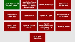
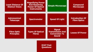
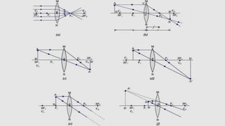
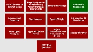
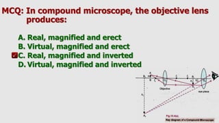
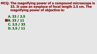
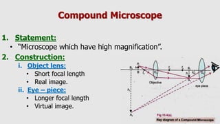
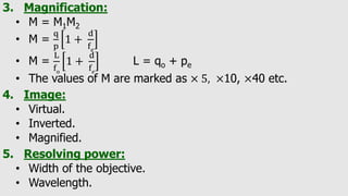
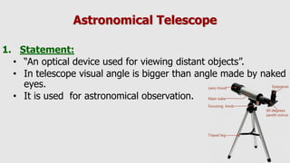
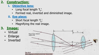
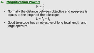
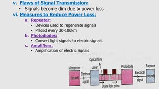
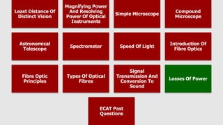
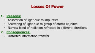
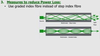
This document discusses various optical instruments and concepts related to fiber optics. It covers the basics of lenses, mirrors, the human eye and various optical devices like microscopes, telescopes and spectrometers. It explains key concepts such as magnification, resolving power, refraction, total internal reflection which enable the working of these instruments. The document also provides an introduction to fiber optics, the principles behind signal transmission using optical fibers and their advantages over traditional copper wiring.
This document provides an overview of different types of telescopes, including refracting and reflecting telescopes, and discusses issues like aberration and how they are addressed. It also covers how telescopes are used to view fainter objects, the limits of angular resolution, and advanced optical telescope designs like the Cassegrain, catadioptric, and Schmidt telescopes. In particular, it notes that refracting telescopes can experience chromatic aberration which can be addressed using an achromatic lens, while reflecting telescopes are prone to spherical aberration addressed using a parabolic mirror.
The document discusses image formation using convex mirrors. It notes that convex mirrors always produce virtual, upright images that are located behind the mirror and are smaller than the object. As the object distance decreases, both the image distance and size increase. So as an object approaches a convex mirror, its virtual image also approaches the mirror and becomes larger. Additionally, the relationship between object and image distances is such that the distance between the image and mirror is always less than between the object and mirror for convex mirrors.
The document discusses key concepts in geometric optics including image formation by flat mirrors, spherical mirrors, refraction through thin lenses, and optical instruments. It covers terminology like real and virtual images, magnification, sign conventions, ray diagrams, and the lens maker's equation. Examples are provided of image formation with various combinations of mirrors and lenses.
ray optics class 12 ppt part 2 slideshareArpit Meena
1. This document summarizes key concepts in ray optics, including refraction through a prism, dispersion, angular dispersion, refractive index, compound microscopes, astronomical telescopes, and resolving power.
2. Refraction through a prism is described using angles of incidence, emergence, deviation and minimum deviation. Dispersion is explained as different colors refracting at different angles due to their different wavelengths.
3. Compound microscopes use an objective and eyepiece lens to magnify images. Astronomical telescopes form real images at focus or virtual images at infinity, with magnification determined by focal lengths.
1. The document discusses the formation of images by convex and concave lenses.
2. For a convex lens, the type, orientation, size and location of the image depends on where the object is placed relative to the focal points of the lens.
3. For a concave lens, the image is always virtual, upright and smaller than the object, regardless of the object's location.
Telescopes use lenses or mirrors to magnify distant objects. There are two main types: refracting and reflecting. Refracting telescopes use lenses and have two main variants - astronomical/Keplerian and Galilean. The astronomical telescope uses a convex objective lens and concave eyepiece to produce an inverted and magnified final image. The Galilean telescope combines a convex objective and concave eyepiece to produce an upright final image without inversion. Reflecting telescopes use curved mirrors instead of lenses.
This document discusses different types of mirrors and how they form images. It describes plane mirrors, which produce images of the same size as the object, and curved mirrors, including concave mirrors that can produce real or virtual images depending on the object's position, and convex mirrors that only produce smaller virtual images. Ray diagrams are introduced as a way to determine the characteristics of images formed by mirrors and lenses. Specific examples of image formation using ray diagrams are provided for concave and convex mirrors.
The document discusses visual angle and its relationship to the apparent size of objects. It then describes how a simple microscope works to magnify objects. Key points:
- Visual angle is the angle subtended by an object on the eye, and a larger visual angle makes an object appear larger. Distance affects visual angle - closer objects have a larger visual angle.
- A simple microscope is a magnifying glass that allows viewing objects closer than the minimum distance of clear vision (25cm). It forms a virtual, upright image using a double convex lens.
- The angular magnification of a simple microscope is calculated using lens formulas and visual angle relationships. It is equal to the distance of the image divided by the focal
Este documento trata sobre espejos y lentes ópticos. Explica que la óptica estudia la trayectoria de la luz al reflejarse o refractarse, representando las ondas luminosas con rayos. Define conceptos como imagen real e imagen virtual, y características de espejos convexos, cóncavos, lentes divergentes y convergentes.
Most of the times this study confused me...so, i just put some important points in one place to easily keep them in mind..hope it will help other students as well..and inform me, if a reader find anything new to improve it further.
Lenses are transparent materials that refract light in a predictable way. They are used to magnify or project images. There are two main types of lenses: convex and concave. Convex lenses are thicker in the center and converge light, forming a real image. Concave lenses are thinner in the center and diverge light, forming a virtual upright image that is smaller than the object. The way light rays behave when passing through lenses can be depicted using ray diagrams to show the characteristics of the image formed.
Telescopes use lenses or mirrors to make distant objects appear larger and closer. Refracting telescopes use lenses to bend and focus light, while reflecting telescopes use curved mirrors. Catadioptric telescopes combine mirrors and lenses. Telescopes are used to observe objects that are too far away to see clearly with the naked eye, without needing to physically get closer. The magnification of a telescope depends on the focal lengths of its objective lens and eyepiece. Larger aperture telescopes can capture more light but have limitations like chromatic aberration.
The document discusses two main types of telescopes - refracting and reflecting. A refracting telescope uses two lenses, a large objective lens that collects light and forms a real image, and an eyepiece lens that magnifies this image for viewing. A reflecting telescope uses a concave mirror instead of an objective lens, collecting light via reflection rather than refraction. Reflecting telescopes are commonly used for large astronomical telescopes as mirrors can be made larger than lenses.
This document discusses different types of lenses used in ophthalmology. It describes spherical lenses and how they are either convex or concave, forming converging or diverging images. It also discusses astigmatic lenses, including cylindrical lenses which have one curved and one plane surface, and toric lenses which have two curved surfaces of different curvatures. The key concepts of focal length, power, vergence, and magnification of lenses are defined.
Light propagates in straight lines and can be reflected, refracted, and diffracted when interacting with matter. Reflection occurs when light hits a smooth surface and bounces back into the same medium at the same angle. Regular reflection occurs from plane mirrors where the angle of incidence equals the angle of reflection. Spherical mirrors can be concave or convex. Concave mirrors form real, inverted images, while convex mirrors form virtual, upright images. The mirror equation relates the focal length and distances of the object and image.
Refraction of light at spherical surfaces of lensesMukesh Tekwani
This document contains 15 important theory questions about refraction of light at spherical surfaces and lenses. It includes questions about sign convention in optics, the optical center of a lens, focal length of concave and convex lenses, lens maker's formula, derivation of expressions for refraction at single spherical surfaces and thin lens combinations, linear magnification by a lens, location of a virtual image formed by a convex lens based on focal length, dependence of focal length on wavelength, definition and unit of power of a lens, definition of 1 dioptre, formula for combined power of two lenses in contact, and laws governing image formation by lenses. The questions cover key concepts like derivation, definition, diagrams, formulas, and image formation.
This document provides an overview of light and vision. It defines luminous and non-luminous objects, and explains that light reflects off of non-luminous objects allowing us to see them. Reflection of light is demonstrated using a ray box experiment. The document also describes the anatomy of the human eye, including the iris, pupil, retina, and lens. It explains how the eye focuses on near and far objects by changing the thickness of the lens. Common vision defects like myopia and hyperopia are also outlined.
The document discusses the reflection of light, including the laws of reflection which state that the angle of incidence equals the angle of reflection and that the incident ray, reflected ray, and normal all lie in the same plane. It also discusses image formation using plane mirrors, including that the image is laterally inverted and as far behind the mirror as the object is in front of it. Convex and concave mirrors are also discussed, including their focal points and how light rays behave depending on the object's position relative to the focal point.
The document discusses different optical devices including lenses, mirrors, and prisms. It focuses on spherical mirrors, describing the two types - concave and convex mirrors. Key details are provided on the center of curvature, radius of curvature, principal axis, pole, focus, and focal length. The mirror formula relating object distance, image distance, and focal length is defined. Characteristics of images formed by concave and convex mirrors in different situations are explained. Uses of concave and convex mirrors are also noted.
This document provides information about ray optics and optical instruments. It begins by defining key concepts in ray optics like reflection, refraction, total internal reflection, and dispersion. It then discusses these phenomena through examples like mirages, diamonds, and prisms. The document also covers topics in geometric optics like mirrors, lenses, the lens maker's formula, and optical instruments like microscopes and telescopes. It provides formulas for magnification, focal length, and angular magnification. In summary, the document is an overview of ray optics concepts and how they apply to the design and use of common optical instruments.
This document discusses concave mirrors and their properties. It describes the key parts of a concave mirror, including the center of curvature, radius of curvature, pole, principal axis, and principal focus. It outlines three main rules for how light rays behave when reflected by a concave mirror. The document also explains the different types of images that are formed when an object is placed at various positions relative to the mirror, such as between the pole and focus, at the focus, or beyond the center of curvature. Finally, it lists some common uses of concave mirrors in devices like car headlights, medical equipment, and solar concentrators.
This document discusses different types of lenses and their properties. It describes thin lenses and how they have two refracting surfaces that are close enough together that the distance between them can be neglected. It explains that a converging lens, also called a convex lens, causes parallel rays of light to converge to a focal point and form a real image. A diverging lens, also called a concave lens, causes parallel rays to diverge after passing through it. The document provides examples of how to use the graphical method to calculate image location and size for different lens types and object positions.
Refraction and Dispersion of light.pptxDakshGupta91
HELLO EVERYONE MY NAME IS DAKSH GUPTA I READ IN CLASS 8 THIS PRESENTATION WILL HELP YOU TO MAKE YOUR OWN PRESENTATION BETTER THAN ME THANK YOU FOR SEEING THIS PRESENTATION
This document summarizes image formation using mirrors, specifically concave and convex mirrors. It discusses the key parts of each type of mirror like focal point and radius of curvature. Properties of the mirrors are explained, such as how concave mirrors form real images while convex mirrors form virtual upright images. Examples of uses for each mirror in daily life are provided. Formulas for calculating image distances and heights are also presented.
The document discusses pantoscopic tilt, which is when the bottom of eyeglass frames are angled toward the cheeks. It describes how proper pantoscopic tilt helps maximize the amount of bridge surface resting on the nose. The document also mentions retroscopic tilt, when the bottom of frames is angled away from the cheeks, and orthoscopic tilt, when frames have no angle. Additionally, it explains how lens tilt improves how glasses look and function for patients, and depends on ear and nose bridge heights, requiring frames to be properly adjusted for individual wearers before measurements.
Optical instruments like magnifying glasses, cameras, microscopes and telescopes extend the capabilities of the human eye. Magnifying glasses allow close examination of small objects like stamps. Cameras can capture events over time like photojournalists do. Microscopes enable the study of tiny organisms. Telescopes help astronomers observe distant heavenly bodies. These tools use lenses or mirrors to enlarge and clarify images beyond the limits of normal vision.
The document discusses optical microscopy and the process of preparing samples for examination under an optical microscope. It begins by explaining the fundamentals of optics and resolution as it relates to wavelength. It then describes the key components of an optical microscope, including the illumination system, condenser, objectives, eyepiece, and stage. The document outlines the principles of image formation, magnification, resolution, depth of field, and aberrations. It also discusses sample preparation techniques such as sectioning, mounting, grinding, polishing, and etching.
The document describes the key components and functioning of a light microscope. It discusses the light source, condenser, stage, objectives of different magnifications, body tube, eyepiece, and how their interaction allows for magnification and imaging of small specimens. The document also covers advantages such as cost-effectiveness and simple sample preparation, and disadvantages like limited resolution and need for staining.
This document provides an overview of basic principles of imaging and lenses. It discusses how light behaves as electromagnetic waves and photons. It explains image formation using pinholes, lenses, and the human eye. Key points covered include how lenses form images by gathering more light than pinholes, issues with lenses like chromatic aberration, and comparisons between the human eye and camera imaging systems.
This document discusses key concepts related to image formation in computer vision. It covers geometric primitives like points, lines, and planes and how they are projected from 3D to 2D. It also discusses image formation in the human eye and digital cameras. The process of capturing digital images involves sampling and quantizing the continuous image function. Factors like spatial resolution, intensity resolution, and image representations like RGB images are also summarized.
This presentation is all about Microscope .... The miracle instrument which revolutionised the study of microbiology and Biological science . Be it Cell studies, molecule studies, pathogen studies, virology etc etc ..... All has become possible for this instrument. let us understand the functioning , applications of this instrument .
Microscopy is the technical field of using microscopes to view objects and areas of objects that cannot be seen with the naked eye (objects that are not within the resolution range of the normal eye). There are three well-known branches of microscopy: optical, electron, and scanning probe microscopy, along with the emerging field of X-ray microscopy.
Microscopy is the technical field of using microscopes to view samples & objects that cannot be seen with the unaided eye (objects that are not within the resolution range of the normal eye).
Optical instruments use lenses to magnify objects or allow viewing of distant objects. Key instruments described include microscopes, telescopes, projectors, cameras, and the human eye. Microscopes have simple or compound lens configurations to produce magnified virtual images. Telescopes use objective and eyepiece lenses separated by the sum of their focal lengths to magnify distant objects. Projectors form enlarged, inverted, real images on screens. Cameras form diminished, inverted images on film. The human eye functions similarly to a camera but can change focal length through accommodation. Common vision defects and their lens-based corrections are also outlined.
The document describes the components and working of a compound microscope. It discusses:
1. The key parts of a compound microscope including the base, pillar, arm, stage, body tube, coarse and fine adjustment screws, draw tube, nosepiece, objectives, and eyepiece.
2. The optical principles of transmission, absorption, diffraction, and refraction that allow light microscopes to work.
3. How light from the illuminator passes through the specimen and objective lens to form a real, inverted intermediate image, which is then magnified by the eyepiece to form a final virtual image visible to the user.
4. Specialized lenses like the oil immersion objective that provide higher
This document discusses reflection and refraction at surfaces and curved surfaces. It begins by explaining the fundamentals of reflection, refraction, and total internal reflection. It then discusses the laws of reflection and refraction. Specific examples of reflection and refraction are provided for plane mirrors, convex mirrors, concave mirrors, and refraction through lenses and the cornea. Clinical applications of reflection and refraction in the eye and optical instruments are described.
This document provides an overview of concepts related to microscopes, telescopes, and their resolving power. It defines key terms like least distance of distinct vision, visual angle, and magnifying power. It then explains the principles of simple microscopes, compound microscopes, and telescopes under stressed and relaxed vision. The document also discusses how resolving power depends on factors like wavelength and aperture diameter. Finally, it includes several practice problems related to calculating magnifying powers and resolving distances for different optical instruments.
OPTICAL MICROSCOPY AND COORDINATE MEASURING MACHINE sangeetkhule
Introduction
Working principle
Classification
Construction and working
Different types of an optical scope
Process capabilities and analysis
Testing
Process parameters
Components and machine structure
Confocal laser scanning microscopy
Microscopic
Advantages
Applications
Advancement in CMM
Machine characteristics
Process parameters of CMM
Animation video
Research papers
Bar graphs and tables
Conclusion
References
A microscope is an instrument used to observe very small organisms i.e. microorganisms. The microscope provides magnification and resolution which makes the image enlarged and fine. There are different types of microscopes ranging from simple to compound microscopes.
Microscopy is the technical field of using microscopes to view objects that are too small to be seen with the naked eye. There are several main types of microscopes, including compound/light microscopes, which use a system of lenses to magnify specimens; darkfield microscopes, which show objects as bright against a dark background; and electron microscopes, which use accelerated electrons rather than light to achieve much higher magnifications down to the nanometer scale. Key aspects of microscopy include factors like resolution, contrast, and magnification that determine what can be observed at microscopic levels.
RAY OPTICS 12 -12-2023.pdf for class 12th studentsasonal761
This document contains a multiple choice test on ray optics concepts. It includes 17 multiple choice questions testing understanding of topics like lenses, mirrors, dispersion, refraction, telescopes and microscopes. The questions cover properties of lenses, principles of minimum deviation, magnification calculations, applications of total internal reflection and differences between various optical instruments. An answer key is provided at the end listing the correct option for each question.
The document discusses different types of microscopes, including compound light microscopes which can magnify up to 1000x and electron microscopes which use beams of electrons instead of light to examine samples at magnifications over 1000x. It describes the key parts of microscopes like the objectives, eyepiece, stage, and mechanical components used to focus and move the microscope. The document also provides information on how biologists use microscopes to study cells and small organisms.
Laboratory session in Physics II subject for September 2016-January 2017 semester in Yachay Tech University (Ecuador). Topic covered: optics, lenses, convergence, divergence, eye, abnormality
Based on Bruna Regalado's work
To Study Principles of Microscopy: Light Microscope, Phase Contrast Microsco...Om Prakash
To Study Principles of Microscopy: Light Microscope, Phase Contrast Microscope & Electron Microscope
ByOm Prakash
June 13, 2022
Write a Comment
on To Study Principles of Microscopy: Light Microscope, Phase Contrast Microscope & Electron Microscope
Aim: To study principles of Microscopy: Light Microscope, Phase Contrast Microscope & Electron Microscope
Table of Contents
THEORETICAL BACKGROUND:
Light Microscopy
History:
SIMPLE MICROSCOPE
Principles of Microscopy:
THE COMPOUND MICROSCOPE
Phase Contrast Microscope
Electron Microscopes
SCANNING ELECTRON MICROSCOPE (SEM)
Also Read
THEORETICAL BACKGROUND:
Light Microscopy
The light microscope is an instrument designed for the study of cells and tissues. It comprises of lenses that produce a magnified image of the object under study. The light microscope is considered to be a simple important invention that has contributed to the advancement of biological research.
History:
The ancient Greeks and Romans knew the use of Glass and quartz lenses. In the 14th century, spectacles and lenses were used to magnify objects. Galileo had constructed a microscope at the same time (1610). It was employed for the study of the arrangement of the compound eye of insects. Anton Von Leeuwenhoek (1674), the father of biology was the first to use the microscope for biological studies. His microscope has consisted of a single lens with a higher power of magnification. The compound microscope was constructed by Robert Hooke (1665) and is the forerunner of the present-day compound microscope.
SIMPLE MICROSCOPE
The simple microscope distinguishes between two points that are less than 0.1mm apart when placed at a normal viewing distance of 25cm. The two points appear as one and the eye fails to resolve or distinguish them as two distinct points. Another limitation of the human eye is that it cannot resolve any image less than 5µm.
A simple microscope consists of a single convex lens or a combination of lenses that functions as a convex lens. A convex lens magnifies the objects and also helps to produce a magnified image of a near object which appears to be at the distance of distinct vision.
The magnification obtained with a convex lens can be easily calculated by the formula
M = 25/f + 1
Where f= focal length, 25 is the distance of distinct vision in cm.
Principles of Microscopy:
1. Resolving power: It is defined as the capacity of the microscope to distinguish images of two pointed objects lying very close together. If two points are at a distance of more than 0.2 µm, they will appear as two points in the microscope.
2. Limit of resolution: It is defined as the minimum distance at which two objects appear as two distinct objects or entities. It can be calculated as:
Limit of Resolution: 0.61λ/NA = 0.61λ/n Sin θ
Where 0.61 is the constant representing the minimum detectable difference in contrast λ = wavelength of illumination
NA = Numerical aperture, light gathering capa
Similar to Chapter 10 Optical Instruments-2.ppt slides (20)
Have you ever been confused by the myriad of choices offered by AWS for hosting a website or an API?
Lambda, Elastic Beanstalk, Lightsail, Amplify, S3 (and more!) can each host websites + APIs. But which one should we choose?
Which one is cheapest? Which one is fastest? Which one will scale to meet our needs?
Join me in this session as we dive into each AWS hosting service to determine which one is best for your scenario and explain why!
Freshworks Rethinks NoSQL for Rapid Scaling & Cost-EfficiencyScyllaDB
Freshworks creates AI-boosted business software that helps employees work more efficiently and effectively. Managing data across multiple RDBMS and NoSQL databases was already a challenge at their current scale. To prepare for 10X growth, they knew it was time to rethink their database strategy. Learn how they architected a solution that would simplify scaling while keeping costs under control.
Building Production Ready Search Pipelines with Spark and MilvusZilliz
Spark is the widely used ETL tool for processing, indexing and ingesting data to serving stack for search. Milvus is the production-ready open-source vector database. In this talk we will show how to use Spark to process unstructured data to extract vector representations, and push the vectors to Milvus vector database for search serving.
zkStudyClub - LatticeFold: A Lattice-based Folding Scheme and its Application...Alex Pruden
Folding is a recent technique for building efficient recursive SNARKs. Several elegant folding protocols have been proposed, such as Nova, Supernova, Hypernova, Protostar, and others. However, all of them rely on an additively homomorphic commitment scheme based on discrete log, and are therefore not post-quantum secure. In this work we present LatticeFold, the first lattice-based folding protocol based on the Module SIS problem. This folding protocol naturally leads to an efficient recursive lattice-based SNARK and an efficient PCD scheme. LatticeFold supports folding low-degree relations, such as R1CS, as well as high-degree relations, such as CCS. The key challenge is to construct a secure folding protocol that works with the Ajtai commitment scheme. The difficulty, is ensuring that extracted witnesses are low norm through many rounds of folding. We present a novel technique using the sumcheck protocol to ensure that extracted witnesses are always low norm no matter how many rounds of folding are used. Our evaluation of the final proof system suggests that it is as performant as Hypernova, while providing post-quantum security.
Paper Link: https://eprint.iacr.org/2024/257
leewayhertz.com-AI in predictive maintenance Use cases technologies benefits ...alexjohnson7307
Predictive maintenance is a proactive approach that anticipates equipment failures before they happen. At the forefront of this innovative strategy is Artificial Intelligence (AI), which brings unprecedented precision and efficiency. AI in predictive maintenance is transforming industries by reducing downtime, minimizing costs, and enhancing productivity.
Digital Marketing Trends in 2024 | Guide for Staying AheadWask
https://www.wask.co/ebooks/digital-marketing-trends-in-2024
Feeling lost in the digital marketing whirlwind of 2024? Technology is changing, consumer habits are evolving, and staying ahead of the curve feels like a never-ending pursuit. This e-book is your compass. Dive into actionable insights to handle the complexities of modern marketing. From hyper-personalization to the power of user-generated content, learn how to build long-term relationships with your audience and unlock the secrets to success in the ever-shifting digital landscape.
In the realm of cybersecurity, offensive security practices act as a critical shield. By simulating real-world attacks in a controlled environment, these techniques expose vulnerabilities before malicious actors can exploit them. This proactive approach allows manufacturers to identify and fix weaknesses, significantly enhancing system security.
This presentation delves into the development of a system designed to mimic Galileo's Open Service signal using software-defined radio (SDR) technology. We'll begin with a foundational overview of both Global Navigation Satellite Systems (GNSS) and the intricacies of digital signal processing.
The presentation culminates in a live demonstration. We'll showcase the manipulation of Galileo's Open Service pilot signal, simulating an attack on various software and hardware systems. This practical demonstration serves to highlight the potential consequences of unaddressed vulnerabilities, emphasizing the importance of offensive security practices in safeguarding critical infrastructure.
A Comprehensive Guide to DeFi Development Services in 2024Intelisync
DeFi represents a paradigm shift in the financial industry. Instead of relying on traditional, centralized institutions like banks, DeFi leverages blockchain technology to create a decentralized network of financial services. This means that financial transactions can occur directly between parties, without intermediaries, using smart contracts on platforms like Ethereum.
In 2024, we are witnessing an explosion of new DeFi projects and protocols, each pushing the boundaries of what’s possible in finance.
In summary, DeFi in 2024 is not just a trend; it’s a revolution that democratizes finance, enhances security and transparency, and fosters continuous innovation. As we proceed through this presentation, we'll explore the various components and services of DeFi in detail, shedding light on how they are transforming the financial landscape.
At Intelisync, we specialize in providing comprehensive DeFi development services tailored to meet the unique needs of our clients. From smart contract development to dApp creation and security audits, we ensure that your DeFi project is built with innovation, security, and scalability in mind. Trust Intelisync to guide you through the intricate landscape of decentralized finance and unlock the full potential of blockchain technology.
Ready to take your DeFi project to the next level? Partner with Intelisync for expert DeFi development services today!
Digital Banking in the Cloud: How Citizens Bank Unlocked Their MainframePrecisely
Inconsistent user experience and siloed data, high costs, and changing customer expectations – Citizens Bank was experiencing these challenges while it was attempting to deliver a superior digital banking experience for its clients. Its core banking applications run on the mainframe and Citizens was using legacy utilities to get the critical mainframe data to feed customer-facing channels, like call centers, web, and mobile. Ultimately, this led to higher operating costs (MIPS), delayed response times, and longer time to market.
Ever-changing customer expectations demand more modern digital experiences, and the bank needed to find a solution that could provide real-time data to its customer channels with low latency and operating costs. Join this session to learn how Citizens is leveraging Precisely to replicate mainframe data to its customer channels and deliver on their “modern digital bank” experiences.
TrustArc Webinar - 2024 Global Privacy SurveyTrustArc
How does your privacy program stack up against your peers? What challenges are privacy teams tackling and prioritizing in 2024?
In the fifth annual Global Privacy Benchmarks Survey, we asked over 1,800 global privacy professionals and business executives to share their perspectives on the current state of privacy inside and outside of their organizations. This year’s report focused on emerging areas of importance for privacy and compliance professionals, including considerations and implications of Artificial Intelligence (AI) technologies, building brand trust, and different approaches for achieving higher privacy competence scores.
See how organizational priorities and strategic approaches to data security and privacy are evolving around the globe.
This webinar will review:
- The top 10 privacy insights from the fifth annual Global Privacy Benchmarks Survey
- The top challenges for privacy leaders, practitioners, and organizations in 2024
- Key themes to consider in developing and maintaining your privacy program
Introduction of Cybersecurity with OSS at Code Europe 2024Hiroshi SHIBATA
I develop the Ruby programming language, RubyGems, and Bundler, which are package managers for Ruby. Today, I will introduce how to enhance the security of your application using open-source software (OSS) examples from Ruby and RubyGems.
The first topic is CVE (Common Vulnerabilities and Exposures). I have published CVEs many times. But what exactly is a CVE? I'll provide a basic understanding of CVEs and explain how to detect and handle vulnerabilities in OSS.
Next, let's discuss package managers. Package managers play a critical role in the OSS ecosystem. I'll explain how to manage library dependencies in your application.
I'll share insights into how the Ruby and RubyGems core team works to keep our ecosystem safe. By the end of this talk, you'll have a better understanding of how to safeguard your code.
Let's Integrate MuleSoft RPA, COMPOSER, APM with AWS IDP along with Slackshyamraj55
Discover the seamless integration of RPA (Robotic Process Automation), COMPOSER, and APM with AWS IDP enhanced with Slack notifications. Explore how these technologies converge to streamline workflows, optimize performance, and ensure secure access, all while leveraging the power of AWS IDP and real-time communication via Slack notifications.
Generating privacy-protected synthetic data using Secludy and MilvusZilliz
During this demo, the founders of Secludy will demonstrate how their system utilizes Milvus to store and manipulate embeddings for generating privacy-protected synthetic data. Their approach not only maintains the confidentiality of the original data but also enhances the utility and scalability of LLMs under privacy constraints. Attendees, including machine learning engineers, data scientists, and data managers, will witness first-hand how Secludy's integration with Milvus empowers organizations to harness the power of LLMs securely and efficiently.
Dandelion Hashtable: beyond billion requests per second on a commodity serverAntonios Katsarakis
This slide deck presents DLHT, a concurrent in-memory hashtable. Despite efforts to optimize hashtables, that go as far as sacrificing core functionality, state-of-the-art designs still incur multiple memory accesses per request and block request processing in three cases. First, most hashtables block while waiting for data to be retrieved from memory. Second, open-addressing designs, which represent the current state-of-the-art, either cannot free index slots on deletes or must block all requests to do so. Third, index resizes block every request until all objects are copied to the new index. Defying folklore wisdom, DLHT forgoes open-addressing and adopts a fully-featured and memory-aware closed-addressing design based on bounded cache-line-chaining. This design offers lock-free index operations and deletes that free slots instantly, (2) completes most requests with a single memory access, (3) utilizes software prefetching to hide memory latencies, and (4) employs a novel non-blocking and parallel resizing. In a commodity server and a memory-resident workload, DLHT surpasses 1.6B requests per second and provides 3.5x (12x) the throughput of the state-of-the-art closed-addressing (open-addressing) resizable hashtable on Gets (Deletes).
2. Least Distance Of
Distinct Vision
Magnifying Power
And Resolving
Power Of Optical
Instruments
Simple Microscope
Compound
Microscope
Astronomical
Telescope
Spectrometer Speed Of Light
Introduction Of
Fibre Optics
Fibre Optic
Principles
Types Of Optical
Fibres
Signal
Transmission And
Conversion To
Sound
Losses Of Power
ECAT Past
Questions
3. MCQ: An object is placed between to parallel
mirrors. The number of images formed is:
A. 2
B. 4
C. 8
D. infinite
4. MCQ: An observer moves towards a plane mirror
with a speed of 2 m/s. The speed of the image
with respect to the observer is:
A. 1 m/s
B. 2 m/s
C. 4 m/s
D. 8 m/s
5. MCQ: A bulb is placed between plane mirrors
inclined at an angle of 60o. The number of
images formed is:
A. 5
B. 6
C. 4
D. 3
6. Least Distance of Distinct Vision
1. Near Point:
• “Minimum distance from the eye at which object can be seen
clearly”.
• d = Near Point = 25 cm = 10 inch.
• d = Far Point = ∞.
• Near point increases with age.
• If an object is held closer to the near point of
eye than image formed will be blurred and fuzzy.
7. 2. Mirror:
• “A highly polished surface from which most of the light is
reflected”.
i. Types of Mirror:
3. Lens:
• “A piece of transparent medium bounded by two surface at
least one of which is curved”.
• Every lens is a part of sphere.
8. i. Types of Lens:
ii. Types of Convex and Concave lens:
9. 4. Image:
• “An image which is located in the plane of convergence for
the light rays that originate from a given object”.
i. Types of Image:
a. Real Image:
• “Image made by convergence of light rays”.
• Real image is always inverted.
• Real image can be projected to the screen.
b. Virtual Image:
• “An image formed when the outgoing rays from a point on an object
always diverge”.
• Virtual image is erect.
• Virtual image cannot be projected
on screen.
10. ii. Number of Images:
• Number of images formed by two mirrors inclined at an angle
′θ′.
• K(number of mirrors) =
360
θ
• Number of image = n = K ( if K is odd )
n= K – 1 ( if K is even )
11. 5. Some important terms:
i. Centre of Curvature:
• “Center of sphere from which spherical surface of lens is
obtained”.
• Every lens has two centers of curvature.
ii. Radius of Curvature:
• “Center of sphere from which spherical surface of lens is
obtained”.
• Every lens has two radii of curvature that may not be equal.
iii. Principle Axis:
• Line joining the two centers of curvature.
iv. Optical Center:
• A point inside the body of lens through which light rays pass
undeviated.
12. v. Principle Focus:
a. Convex Lens:
• A point of convergence of refracted light rays.
• It is a real point.
b. Concave Lens:
• A point of divergence of refracted light rays.
• It is imaginary point.
vi. Focal Length:
• A distance between principle focus and optical center.
• Convex lens + ve.
• Concave lens – ve.
vii. Aperture:
• The size of diameter of lens.
13. viii. Ray of Light:
• A straight line path along which the transfer of light energy take
place.
• It is represented by a straight line with arrow marked on it.
a. Types of rays:
ix. Beam of Light:
• A relatively large bundle of rays of light.
14. Least Distance Of
Distinct Vision
Magnifying Power
And Resolving
Power Of Optical
Instruments
Simple Microscope
Compound
Microscope
Astronomical
Telescope
Spectrometer Speed Of Light
Introduction Of
Fibre Optics
Fibre Optic
Principles
Types Of Optical
Fibres
Signal
Transmission And
Conversion To
Sound
Losses Of Power
ECAT Past
Questions
15. MCQ: A man of height 1.6 m wishes to see his full image in
a plane mirror placed at a distance of 2 m.
The minimum height of the mirror should be:
A. 0.5 m
B. 0.8 m
C. 1.6 m
D. 2.4 m
16. Magnifying Power and Resolving Power of
Optical Instruments
1. Magnifying Power:
i. Linear Magnification:
• “The ratio of size of image to size of object”.
• M =
hi
ho
=
q
p
ii. Angular Magnification:
• “The ratio of the angle subtended by the image as seen through
the optical device to that subtended by the by the object”.
• M =
tanα
tanβ
17. • When the same object is viewed at a shorter distance, the
image on the retina of the eye is greater, so the object appears
large.
• For very small angle ‘linear magnification’ is equal to ‘angular
magnification’.
2. Resolving Power:
• “Ability to reveal the mirror details of the object under
examination”.
i. Angle of Resolution:
• “The minimum angle that allows two point sources to appear
distinctly separated”.
• It is expressed as ∝min.
18. ∝min = 1.22
λ
D
.
• Resolving power of lens of aperture D, under light source of
wavelength λ is,
R =
D
1.22λ
=
1
∝min
Resolving Power
Human Eye
𝛂 = 𝟏 𝐦𝐢𝐧
R ∝
𝟏
𝛂
Microscope
d =
𝛌
𝟐𝛍𝐬𝐢𝐧𝛉
R ∝
𝟏
𝐝
Telescope
𝛂 =
𝛌
𝟏. 𝟐𝟐𝐃
R ∝
𝟏
𝛂
Grating
R = N × m
R =
𝛌
∆𝛌
19. Least Distance Of
Distinct Vision
Magnifying Power
And Resolving
Power Of Optical
Instruments
Simple Microscope
Compound
Microscope
Astronomical
Telescope
Spectrometer Speed Of Light
Introduction Of
Fibre Optics
Fibre Optic
Principles
Types Of Optical
Fibres
Signal
Transmission And
Conversion To
Sound
Losses Of Power
ECAT Past
Questions
20. MCQ: When object is placed between F and 2F, the
image are formed:
A. At 2 F
B. Between F and 2F
C. Beyond 2F
D. At F
21. MCQ: What is the minimum and maximum distance
between the convex lens and object for the
magnification of a real image to be greater than 1?
A. f and infinity
B. 2 f and infinity
C. f and 2 f
D. 0 and f
22. MCQ: The focal length of a simple magnifier is
12.5 cm. Its magnifying power if the final image is
formed at 25 cm in front of the eye is:
A. 2
B. 3
C. -3
D. 1
23. Simple Microscope
1. Simple Microscope:
• “An instrument used to see objects that are too small for the
naked eye”.
i. Angular Magnification:
• M =
β
α
=
I
O
ii. Magnification for Real and Virtual Image:
• For real image:
• M =
q
p
=
d
p
24. • For virtual image:
• M = 1 +
d
f
iii. Position of Object and Image:
Sr. no. Position of Object Position of Image
1. At infinity At focus
2. At focus At infinity
3. Beyond 2F Between F and 2F
4. At 2F At 2F
5. Between F and 2F Beyond 2F
6. Between F and optical centre On the same side as the object
25.
26. Least Distance Of
Distinct Vision
Magnifying Power
And Resolving
Power Of Optical
Instruments
Simple Microscope
Compound
Microscope
Astronomical
Telescope
Spectrometer Speed Of Light
Introduction Of
Fibre Optics
Fibre Optic
Principles
Types Of Optical
Fibres
Signal
Transmission And
Conversion To
Sound
Losses Of Power
ECAT Past
Questions
27. MCQ: In compound microscope, the objective lens
produces:
A. Real, magnified and erect
B. Virtual, magnified and erect
C. Real, magnified and inverted
D. Virtual, magnified and inverted
28. MCQ: The magnifying power of a compound microscope is
33. It uses an eyepiece of focal length 2.5 cm. The
magnifying power of objective is:
A. 33 / 2.5
B. 33 / 11
C. 2.5 / 33
D. 2.5 / 11
29. MCQ: A compound microscope has a magnification of 24.
The focal length of the eye piece is 5 cm. If the final
image is formed at the least distance of distinct
vision, the magnification produced by the objective
is:
A. 3
B. 4
C. 5
D. 12
30. Compound Microscope
1. Statement:
• “Microscope which have high magnification”.
2. Construction:
i. Object lens:
• Short focal length
• Real image.
ii. Eye – piece:
• Longer focal length
• Virtual image.
31. 3. Magnification:
• M = M1M2
• M =
q
p
1 +
d
f𝑒
• M =
L
fo
1 +
d
f𝑒
L = qo + pe
• The values of M are marked as × 5, ×10, ×40 etc.
4. Image:
• Virtual.
• Inverted.
• Magnified.
5. Resolving power:
• Width of the objective.
• Wavelength.
32. MCQ: If a convex lens of focal length f is cut into
identical halves along the lens diameter, the
focal length of each half is:
A. 2 f
B. f / 2
C. f
D. Zero
33. MCQ: The focal length of a simple magnifier is
12.5 cm. Its magnifying power? If the final
image is formed 25 cm in front of the eye is:
A. 2 f
B. f / 2
C. f
D. Zero
34. MCQ: Two convex lenses (f1 , f2) are joined side by
side their focal length will reduce to half if:
A. f1 < f2
B. f1 = f2
C. f1 > f2
D. f1 = f2 = ∞
35. MCQ: Magnification of a compound microscope is 10. If
magnification of eyepiece is 5 cm and focal length of
objective is 8 cm. Then the length of microscope is:
A. 4 cm
B. 16 cm
C. 400 cm
D. 32 cm
36. MCQ: If a lens is immersed in water its focal length
will be:
A. Increase
B. Decrease
C. Remain same
D. None of these
37. Least Distance Of
Distinct Vision
Magnifying Power
And Resolving
Power Of Optical
Instruments
Simple Microscope
Compound
Microscope
Astronomical
Telescope
Spectrometer Speed Of Light
Introduction Of
Fibre Optics
Fibre Optic
Principles
Types Of Optical
Fibres
Signal
Transmission And
Conversion To
Sound
Losses Of Power
ECAT Past
Questions
38. Astronomical Telescope
1. Statement:
• “An optical device used for viewing distant objects”.
• In telescope visual angle is bigger than angle made by naked
eyes.
• It is used for astronomical observation.
39. 2. Construction:
i. Objective lens:
• Long focal length ‘fo’.
• Formed real, inverted and diminished image.
ii. Eye piece:
• Short focal length ‘fe’.
• Magnifying the real image.
3. Image:
• Virtual
• Enlarge
• Inverted
40. 4. Magnification Power:
M =
fo
fe
• Normally the distance between objective and eye-piece is
equals to the length of the telescope.
L = fo + fe
• Good telescope has an objective of long focal length and
large aperture.
41. Least Distance Of
Distinct Vision
Magnifying Power
And Resolving
Power Of Optical
Instruments
Simple Microscope
Compound
Microscope
Astronomical
Telescope
Spectrometer Speed Of Light
Introduction Of
Fibre Optics
Fibre Optic
Principles
Types Of Optical
Fibres
Signal
Transmission And
Conversion To
Sound
Losses Of Power
ECAT Past
Questions
42. Spectrometer
1. Statement:
• “An optical device used to study spectra from different
sources of light”.
2. Uses of Spectrometer:
• Deviation of light.
• Refractive index of material.
• Wavelength of light.
43. 3. Components of a Spectrometer:
i. Collimator:
• It contain metallic tube with convex lens at one end and an
adjustable tube at the other end.
• “It makes the light beams parallel”.
ii. Turn Table:
• A prims (for rotating vertical axis).
• A circular scale (graduated in half degree).
iii. Telescope:
• Telescope is attached with vernier scale
and rotatable with vertical axis.
44. Least Distance Of
Distinct Vision
Magnifying Power
And Resolving
Power Of Optical
Instruments
Simple Microscope
Compound
Microscope
Astronomical
Telescope
Spectrometer Speed Of Light
Introduction Of
Fibre Optics
Fibre Optic
Principles
Types Of Optical
Fibres
Signal
Transmission And
Conversion To
Sound
Losses Of Power
ECAT Past
Questions
45. Speed Of Light
1. Measurement of Speed of Light:
• 1st measured by Galileo
• Measured accurately by Michelson
2. Michelson’s Formula:
• c = 16fd
• f= frequency of rotation of octagonal mirror
• d= distance between plane mirror and octagonal mirror
• c = 3.00 x 10⁸ ms-1
46. 3. Speed of Light:
i. In Space:
• 3 x 10⁸ ms-1
ii. In other Materials:
• Always less than 3 x 10⁸ ms-1
47. Least Distance Of
Distinct Vision
Magnifying Power
And Resolving
Power Of Optical
Instruments
Simple Microscope
Compound
Microscope
Astronomical
Telescope
Spectrometer Speed Of Light
Introduction Of
Fibre Optics
Fibre Optic
Principles
Types Of Optical
Fibres
Signal
Transmission And
Conversion To
Sound
Losses Of Power
ECAT Past
Questions
48. Introduction Of Fibre Optics
1. Optical Fibre:
• A device that propagates signals using light
• “A flexible, transparent fiber made by drawing glass (silica) or
plastic to a diameter slightly thicker than that of a human
hair”.
49. 2. Photophone:
• Transmit voice message via beam of light
• Invented by Graham Bell
• Light is used as a transmission carrier wave
3. Introduction:
• Alexander Graham Bell invented ‘photo phone’.
• Bell transmit voice message via a beam of light.
4. Advantages:
• Light use as transmission carrier wave due to;
• Wider bandwidth capability.
• Immunity from electromagnetic interference.
50. 5. Importance of Fibre Optics:
• 1000’s telephone calls, several TV channels through 1 or 2
hair - thin threads.
• Word processing, image transmitting and receiving
equipment's to operate efficiently.
• Much thinner and light weight cables.
• Optical fibre = 6.0 mm.
• Copper wire = 7.62 cm
51. Least Distance Of
Distinct Vision
Magnifying Power
And Resolving
Power Of Optical
Instruments
Simple Microscope
Compound
Microscope
Astronomical
Telescope
Spectrometer Speed Of Light
Introduction Of
Fibre Optics
Fibre Optic
Principles
Types Of Optical
Fibres
Signal
Transmission And
Conversion To
Sound
Losses Of Power
ECAT Past
Questions
52. Fibre Optic Principles
1. Principle of Transmitting Signals in Optical Fibres:
i. Total Internal Reflection:
• “A phenomenon which occurs when a propagating wave strikes
a medium boundary at an angle larger than a particular critical
angle with respect to the normal to the surface”.
• n =
C
V
• n1sinθ1 = n2sinθ2
• sinθc =
n2
n1
• For glass θc= 41.8o.
54. Least Distance Of
Distinct Vision
Magnifying Power
And Resolving
Power Of Optical
Instruments
Simple Microscope
Compound
Microscope
Astronomical
Telescope
Spectrometer Speed Of Light
Introduction Of
Fibre Optics
Fibre Optic
Principles
Types Of Optical
Fibers
Signal
Transmission And
Conversion To
Sound
Losses Of Power
ECAT Past
Questions
55. Types Of Optical Fibres
1. Single Mode Step Index Fibre:
• Core 5 μm diameter.
• Cladding (glass or plastic)
• Monochromatic light source
• 14 TV channels
• 14000 phone calls.
56. 2. Multimode Step Index Fibre:
• Mode of transmission is total internal reflection
• Useful for short distances
• Core 50 μm diameter.
• White light.
• Short range.
• Refractive Index;
• Core = 1.52
• Cladding = 1.48
57. 3. Multimode Graded Index Fibre:
• Core diameter is 50 -100𝜇m
• No noticeable boundary
• Mode of transmission is continuous refraction
• suitable for long distance travel
58.
59. Least Distance Of
Distinct Vision
Magnifying Power
And Resolving
Power Of Optical
Instruments
Simple Microscope
Compound
Microscope
Astronomical
Telescope
Spectrometer Speed Of Light
Introduction Of
Fibre Optics
Fibre Optic
Principles
Types Of Optical
Fibres
Signal
Transmission And
Conversion To
Sound
Losses Of Power
ECAT Past
Questions
60. Signal Transmission And Conversion To Sound
1. Components of Fiber Optics Communication System:
i. Light Source:
• Semiconductor laser and LED (invisible infra-red signals)
ii. Transmitter:
• Convert electrical signals to light
iii. Optical Fibre:
• For guiding of signals
iv. Receiver:
• Capture light signals at other end of the fibre
• Reconvert to electrical signals
61. 2. Digital Modulation of Light Waves:
• LED flashed on and off on extremely fast rate
• On 1
• Off 0
i. Coding:
• Represented by a particular pattern of 1s and 0s
ii. Decoding:
• 1s and 0s pattern is decoded in analogue form i.e picture, voice,
video
iii. Unit of Digital Modulation:
• bits (a 1 and a 0)
• megabits
62. v. Flaws of Signal Transmission:
• Signals become dim due to power loss
vi. Measures to Reduce Power Loss:
a. Repeater:
• Devices used to regenerate signals
• Placed every 30-100km
b. Photodiodes:
• Convert light signals to electric signals
c. Amplifiers:
• Amplification of electric signals
63. Least Distance Of
Distinct Vision
Magnifying Power
And Resolving
Power Of Optical
Instruments
Simple Microscope
Compound
Microscope
Astronomical
Telescope
Spectrometer Speed Of Light
Introduction Of
Fibre Optics
Fibre Optic
Principles
Types Of Optical
Fibres
Signal
Transmission And
Conversion To
Sound
Losses Of Power
ECAT Past
Questions
64. Losses Of Power
1. Reasons:
• Absorption of light due to impurities
• Scattering of light due to group of atoms at joints
• Narrow band of radiation refracted in different directions
2. Consequences:
• Distorted information transfer
65. 3. Measures to reduce Power Loss:
• Use graded index fibre instead of step index fibre
66. Least Distance Of
Distinct Vision
Magnifying Power
And Resolving
Power Of Optical
Instruments
Simple Microscope
Compound
Microscope
Astronomical
Telescope
Spectrometer Speed Of Light
Introduction Of
Fibre Optics
Fibre Optic
Principles
Types Of Optical
Fibres
Signal
Transmission And
Conversion To
Sound
Losses Of Power
ECAT Past
Questions
67. MCQ: From going one medium to another which
does not change:
A. Frequency
B. Speed
C. Wavelength
D. All
ECAT
2012
68. MCQ: A convex lens of 20 cm, focal length is used to
form an erect image is twice as large as the object.
The position of the object from the lens is:
A. 10 cm
B. 30 cm
C. 20 cm
D. 15 cm
ECAT
2012
69. MCQ: In astronomical telescope the final image is
formed at:
A. Near point
B. Far point
C. Infinity
D. None of these
ECAT
2011