This document describes an experiment to observe and measure Newton's rings to determine the wavelength of sodium light. Key points:
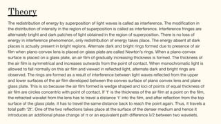
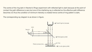
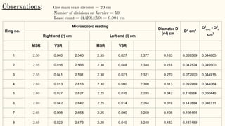
- Newton's rings are bright and dark interference rings formed between a plano-convex lens and glass plate due to varying film thickness.
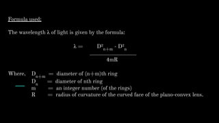
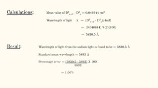
- The wavelength of light can be calculated using the diameter measurements of different rings and the lens's radius of curvature.
- The experiment was performed and the wavelength of sodium light was calculated to be 5830.5 Angstroms with a 1.06% error from the standard value of 5893 Angstroms.


![Newtons_Rings_Detailed[1].pptxsssssssssssssss](https://cdn.slidesharecdn.com/ss_thumbnails/newtonsringsdetailed1-250421113708-88d6350e-thumbnail.jpg?width=640&height=640&fit=bounds)


![Final_Newtons_Rings_Presentation[1].pptx](https://cdn.slidesharecdn.com/ss_thumbnails/finalnewtonsringspresentation1-250611150331-b9a873ee-thumbnail.jpg?width=640&height=640&fit=bounds)


![[Deck] What's New in Spark-Iceberg Integration via DSV2.pptx](https://cdn.slidesharecdn.com/ss_thumbnails/deckwhatsnewinspark-icebergintegrationviadsv2-260210005337-25955b12-thumbnail.jpg?width=640&height=640&fit=bounds)


