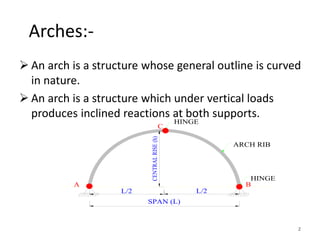
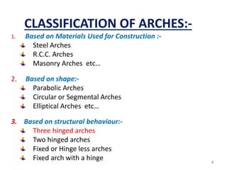
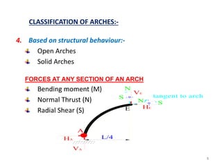
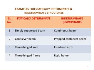
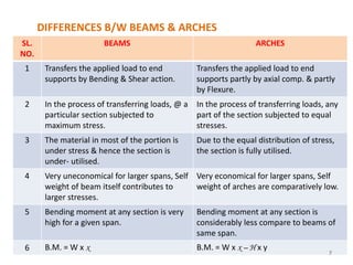
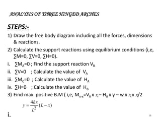
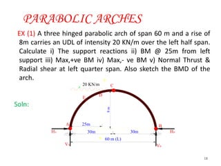
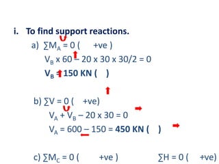
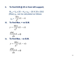
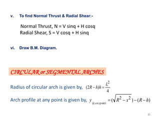
THREE HINGED ARCHES
1
M.Arun Kumar
Assistant Professor
Kongu Engineering College,
Erode
Arches:-
 An arch is a structure whose general outline is curved
in nature.
 An arch is a structure which under vertical loads
produces inclined reactions at both supports.
2
CENTRAL
RISE
(h)
SPAN (L)
HINGE
HINGE
L/2 L/2
ARCH RIB
A B
C
We have 3-hinged, 2-hinged and fixed arches.
1-Three-hinged arches are statically determinate; hence,
horizontal displacement of the abutments does not produce
any additional stresses on the structural system.
2- Two-hinged arches and the fixed arches are statically
indeterminate; hence, displacement of the abutments
produces additional stresses in the structural system.
Furthermore, foundations of such arches should be on rock or
on very solid gravel.
3
CLASSIFICATION OF ARCHES:-
1. Based on Materials Used for Construction :-
Steel Arches
R.C.C. Arches
Masonry Arches etc…
2. Based on shape:-
Parabolic Arches
Circular or Segmental Arches
Elliptical Arches etc…
3. Based on structural behaviour:-
Three hinged arches
Two hinged arches
Fixed or Hinge less arches
Fixed arch with a hinge 4
CLASSIFICATION OF ARCHES:-
4. Based on structural behaviour:-
Open Arches
Solid Arches
FORCES AT ANY SECTION OF AN ARCH
Bending moment (M)
Normal Thrust (N)
Radial Shear (S)
5
L/4
A
HE
VE
S
N
tangent to arch


S
N
HA
VA
E
6
Sl.
No.
STATICALLY DETERMINATE INDETERMINATE
(HYPERSTATIC)
1 Simply supported beam Continuous beam
2 Cantilever beam Propped cantilever beam
3 Three-hinged arch Fixed end arch
4 Three-hinged frame Rigid frame
EXAMPLES FOR STATICALLY DETERMINATE &
INDETERMINATE STRUCTURES
DIFFERENCES B/W BEAMS & ARCHES
SL.
NO.
BEAMS ARCHES
1 Transfers the applied load to end
supports by Bending & Shear action.
Transfers the applied load to end
supports partly by axial comp. & partly
by Flexure.
2 In the process of transferring loads, @ a
particular section subjected to
maximum stress.
In the process of transferring loads, any
part of the section subjected to equal
stresses.
3 The material in most of the portion is
under stress & hence the section is
under- utilised.
Due to the equal distribution of stress,
the section is fully utilised.
4 Very uneconomical for larger spans, Self
weight of beam itself contributes to
larger stresses.
Very economical for larger spans, Self
weight of arches are comparatively low.
5 Bending moment at any section is very
high for a given span.
Bending moment at any section is
considerably less compare to beams of
same span.
6 B.M. = W x x B.M. = W x x – H x y
7
8
9
Forces
 Compression – a
pushing or squeezing
force
 Tension – a pulling or
stretching force
 Keystone – the
wedge-shaped stone
of an arch that locks
its parts together
 Abutments – the
structures that
support the ends of
the bridge
10
CONSTRUCTION OF AN ARCH
 Works by
Compression
11
Cold Spring Arch Bridge, Santa Barbara, CA
Cable-Stayed
Bridges
• Piers – the vertical supporting structures
• Cables – thick steel ropes from which the decking is
suspended
• Decking – the supported roadway on a bridge
12
Cable-Stayed Bridges
• Works by Tension AND Compression
13
Suspension Bridges
• Similar to Cable-Stayed
• Different construction method
14
Suspension Bridges
• Works by Tension and Compression
15
ANALYSIS OF THREE HINGED ARCHES
STEPS:-
1) Draw the free body diagram including all the forces, dimensions
& reactions.
2) Calculate the support reactions using equilibrium conditions (i,e,
∑M=0, ∑V=0, ∑H=0).
i. ∑MA=0 ; Find the support reaction VB
ii. ∑V=0 ; Calculate the value of VA
iii. ∑MC=0 ; Calculate the value of HA
iv. ∑H=0 ; Calculate the value of HB
3) Find max. positive B.M ( i,e, Mx-x=VA x x – HA x y – w x x x x/2
i. 16
)
(
4
2
x
L
L
hx
y 

0


dx
dM x
x
17
ii. Find value of “x’ by using condition
; x = ---------- m
iii. Substitute the value of ‘x’ in moment equation; calculate the value
of max. B.M.
4) Then use the same procedure to find – ve B.M
5) Normal thrust & Radial shear at any point of the arch is given by
Normal Thrust, N = V sin + H cos
Radial Shear, S = V cos + H sin
where ‘’ can be calculated as ;
6) Draw B.M.Diagram for the given arch.
)
2
(
4
tan
2
x
L
L
h
dx
dy


 
PARABOLIC ARCHES
18
EX (1) A three hinged parabolic arch of span 60 m and a rise of
8m carries an UDL of intensity 20 KN/m over the left half span.
Calculate i) The support reactions ii) BM @ 25m from left
support iii) Max,+ve BM iv) Max,- ve BM v) Normal Thrust &
Radial shear at left quarter span. Also sketch the BMD of the
arch.
Soln: 8
m
60 m (L)
30m 30m
A B
C
20 KN/m
25m
E
D
HB
VB
HA
VA
x
x
i. To find support reactions.
a) ∑MA = 0 ( +ve )
VB x 60 – 20 x 30 x 30/2 = 0
VB = 150 KN ( )
b) ∑V = 0 ( +ve)
VA + VB – 20 x 30 = 0
VA = 600 – 150 = 450 KN ( )
c) ∑MC = 0 ( +ve ) ∑H = 0 ( +ve)
19
20
ii. To find B.M @ 25 m from left support,
Mx-x= VA x 25 – HA x yD – 20 X 25 x 25/2
(Rise) yD can be calculated as follows
yD =
iii. To find Max. + ve B.M.
iv. To find Max. - ve B.M.
)
(
4
2
x
L
L
hx

)
(
4
2
x
L
L
hx
y 

0


dx
dM x
x
)
(
4
2
x
L
L
hx
y 

0


dx
dM x
x
21
v. To find Normal Thrust & Radial Shear:-
Normal Thrust, N = V sinq + H cosq
Radial Shear, S = V cosq + H sinq
vi. Draw B.M. Diagram.
Radius of circular arch is given by,
Arch profile at any point is given by,
CIRCULAR or SEGMENTAL ARCHES
4
)
2
(
2
L
h
h
R 

)
(
)
( 2
2
int
@
h
R
x
R
y anypo




22
Cold Spring Arch Bridge, Santa Barbara, CA
23
Marsh Rainbow Arch, Riverton, KS
24
Pont du Gard, Nimes, France
Iron bridge, River Severn, England, built by Abraham Darby, 1779.
Members in compression; connections using dowels etc. 25
St Louis Rail Bridge, St Louis USA, Mississippi River. James Eades, 1874. First
true steel bridge. Three spans, each 152 m. 26
27
THANK YOU

SA II Unit 4.ppt

  • 1.
    THREE HINGED ARCHES 1 M.ArunKumar Assistant Professor Kongu Engineering College, Erode
  • 2.
    Arches:-  An archis a structure whose general outline is curved in nature.  An arch is a structure which under vertical loads produces inclined reactions at both supports. 2 CENTRAL RISE (h) SPAN (L) HINGE HINGE L/2 L/2 ARCH RIB A B C
  • 3.
    We have 3-hinged,2-hinged and fixed arches. 1-Three-hinged arches are statically determinate; hence, horizontal displacement of the abutments does not produce any additional stresses on the structural system. 2- Two-hinged arches and the fixed arches are statically indeterminate; hence, displacement of the abutments produces additional stresses in the structural system. Furthermore, foundations of such arches should be on rock or on very solid gravel. 3
  • 4.
    CLASSIFICATION OF ARCHES:- 1.Based on Materials Used for Construction :- Steel Arches R.C.C. Arches Masonry Arches etc… 2. Based on shape:- Parabolic Arches Circular or Segmental Arches Elliptical Arches etc… 3. Based on structural behaviour:- Three hinged arches Two hinged arches Fixed or Hinge less arches Fixed arch with a hinge 4
  • 5.
    CLASSIFICATION OF ARCHES:- 4.Based on structural behaviour:- Open Arches Solid Arches FORCES AT ANY SECTION OF AN ARCH Bending moment (M) Normal Thrust (N) Radial Shear (S) 5 L/4 A HE VE S N tangent to arch   S N HA VA E
  • 6.
    6 Sl. No. STATICALLY DETERMINATE INDETERMINATE (HYPERSTATIC) 1Simply supported beam Continuous beam 2 Cantilever beam Propped cantilever beam 3 Three-hinged arch Fixed end arch 4 Three-hinged frame Rigid frame EXAMPLES FOR STATICALLY DETERMINATE & INDETERMINATE STRUCTURES
  • 7.
    DIFFERENCES B/W BEAMS& ARCHES SL. NO. BEAMS ARCHES 1 Transfers the applied load to end supports by Bending & Shear action. Transfers the applied load to end supports partly by axial comp. & partly by Flexure. 2 In the process of transferring loads, @ a particular section subjected to maximum stress. In the process of transferring loads, any part of the section subjected to equal stresses. 3 The material in most of the portion is under stress & hence the section is under- utilised. Due to the equal distribution of stress, the section is fully utilised. 4 Very uneconomical for larger spans, Self weight of beam itself contributes to larger stresses. Very economical for larger spans, Self weight of arches are comparatively low. 5 Bending moment at any section is very high for a given span. Bending moment at any section is considerably less compare to beams of same span. 6 B.M. = W x x B.M. = W x x – H x y 7
  • 8.
  • 9.
    9 Forces  Compression –a pushing or squeezing force  Tension – a pulling or stretching force
  • 10.
     Keystone –the wedge-shaped stone of an arch that locks its parts together  Abutments – the structures that support the ends of the bridge 10 CONSTRUCTION OF AN ARCH
  • 11.
     Works by Compression 11 ColdSpring Arch Bridge, Santa Barbara, CA
  • 12.
    Cable-Stayed Bridges • Piers –the vertical supporting structures • Cables – thick steel ropes from which the decking is suspended • Decking – the supported roadway on a bridge 12
  • 13.
    Cable-Stayed Bridges • Worksby Tension AND Compression 13
  • 14.
    Suspension Bridges • Similarto Cable-Stayed • Different construction method 14
  • 15.
    Suspension Bridges • Worksby Tension and Compression 15
  • 16.
    ANALYSIS OF THREEHINGED ARCHES STEPS:- 1) Draw the free body diagram including all the forces, dimensions & reactions. 2) Calculate the support reactions using equilibrium conditions (i,e, ∑M=0, ∑V=0, ∑H=0). i. ∑MA=0 ; Find the support reaction VB ii. ∑V=0 ; Calculate the value of VA iii. ∑MC=0 ; Calculate the value of HA iv. ∑H=0 ; Calculate the value of HB 3) Find max. positive B.M ( i,e, Mx-x=VA x x – HA x y – w x x x x/2 i. 16 ) ( 4 2 x L L hx y  
  • 17.
    0   dx dM x x 17 ii. Findvalue of “x’ by using condition ; x = ---------- m iii. Substitute the value of ‘x’ in moment equation; calculate the value of max. B.M. 4) Then use the same procedure to find – ve B.M 5) Normal thrust & Radial shear at any point of the arch is given by Normal Thrust, N = V sin + H cos Radial Shear, S = V cos + H sin where ‘’ can be calculated as ; 6) Draw B.M.Diagram for the given arch. ) 2 ( 4 tan 2 x L L h dx dy    
  • 18.
    PARABOLIC ARCHES 18 EX (1)A three hinged parabolic arch of span 60 m and a rise of 8m carries an UDL of intensity 20 KN/m over the left half span. Calculate i) The support reactions ii) BM @ 25m from left support iii) Max,+ve BM iv) Max,- ve BM v) Normal Thrust & Radial shear at left quarter span. Also sketch the BMD of the arch. Soln: 8 m 60 m (L) 30m 30m A B C 20 KN/m 25m E D HB VB HA VA x x
  • 19.
    i. To findsupport reactions. a) ∑MA = 0 ( +ve ) VB x 60 – 20 x 30 x 30/2 = 0 VB = 150 KN ( ) b) ∑V = 0 ( +ve) VA + VB – 20 x 30 = 0 VA = 600 – 150 = 450 KN ( ) c) ∑MC = 0 ( +ve ) ∑H = 0 ( +ve) 19
  • 20.
    20 ii. To findB.M @ 25 m from left support, Mx-x= VA x 25 – HA x yD – 20 X 25 x 25/2 (Rise) yD can be calculated as follows yD = iii. To find Max. + ve B.M. iv. To find Max. - ve B.M. ) ( 4 2 x L L hx  ) ( 4 2 x L L hx y   0   dx dM x x ) ( 4 2 x L L hx y   0   dx dM x x
  • 21.
    21 v. To findNormal Thrust & Radial Shear:- Normal Thrust, N = V sinq + H cosq Radial Shear, S = V cosq + H sinq vi. Draw B.M. Diagram. Radius of circular arch is given by, Arch profile at any point is given by, CIRCULAR or SEGMENTAL ARCHES 4 ) 2 ( 2 L h h R   ) ( ) ( 2 2 int @ h R x R y anypo    
  • 22.
    22 Cold Spring ArchBridge, Santa Barbara, CA
  • 23.
  • 24.
    24 Pont du Gard,Nimes, France
  • 25.
    Iron bridge, RiverSevern, England, built by Abraham Darby, 1779. Members in compression; connections using dowels etc. 25
  • 26.
    St Louis RailBridge, St Louis USA, Mississippi River. James Eades, 1874. First true steel bridge. Three spans, each 152 m. 26
  • 27.