Download to read offline
![08
TECHNICAL DATA
Reading head: 200 µm grating pitch
Scale unit
Permissible vibration:
150 m/s2
(40 to 2000 Hz)
Permissible shock:
750 m/s2
(8 ms)
Permissible temperature:
–20 °C to +70 °C (storage), 0 °C to +60 °C (operation)
RoHS-conformity:
The Linear Encoders of the MS 45 series comply with the guideline of the RoHS-directive 2011/65/EU on
the restriction of the use of certain hazardous substances in electrical and electronic equipment
Scale
model
Output
signals
System resolution
[µm]
Integrated
interpolation
Max.
velocity [m/s]
Max. output
frequency [kHz]
MS 45.06 1 Vpp
depending on
external interpolation
-- 15 75
Edge separation
amin
MS 45.66 10 times5 10.0 500 ns
MS 45.76 5 times10 9.6 500 ns
MS 45.86 1 times50 4.8 200 ns
MS 45.96 0.5 times100 2.4 200 ns
Pattern of standard reference marks
Mechanical features of the scale unit
Grating carrier steel
Grating pitch (T) 200 µm
Accuracy grades ±30 µm/m
Non-linearity ±5 µm/m
Maximum measuring length (ML) 30 000 mm
Reference marks (RI) standard: 100 mm (equidistant)
at any location, on request
ELECTROMATE
Toll Free Phone (877) SERVO98
Toll Free Fax (877) SERV099
www.electromate.com
sales@electromate.com
Sold Serviced By:](https://image.slidesharecdn.com/rsfelectronikms45seriescatalog-150209112832-conversion-gate01/85/Rsf-electronik-ms45_series_catalog-8-320.jpg)
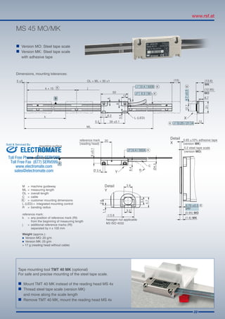
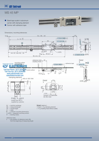


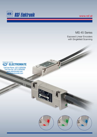
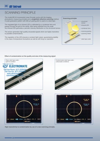
The document discusses the MS 45 series of exposed linear encoders. It provides details on their scanning principles, output signals, technical specifications, and dimensions. The encoders use a singlefield reflective scanning method with a 200 micrometer grating pitch. They are designed for contamination resistance, high resolution, speed, and easy mounting.