Downloaded 44 times

![4
S-N800UR2
910
—
—
250
300
600
600
—
—
—
—
—
—
12004
–
S(D)-N11(CX)
S(D)-N12(CX)
20
1/2
1-1/2
3
3
7-1/2
7-1/2
MSO-
N11KP(CX)
N12KP(CX)
3
3
7-1/2
7-1/2
30
–
S-N10(CX)
13
1/2
1-1/2
3
3
5
5
MSO-
N10KP(CX)
3
3
5
5
30
–
A
120V HP
240V HP
208V HP
240V HP
480V HP
600V HP
208V HP
240V HP
480V HP
600V HP
A
A
Conta-
ctor
(open)
Starter
(open)
Max. rating of short
circuit protection device
Fuse class K5
Circuit breaker
S-N18(CX)
30
1
3
5
5
10
10
MSO-
N18KP(CX)
5
5
10
10
70
–
S-N20(CX)
S(D)-N21(CX)
30
1
3
5
5
10
10
MSO-
N20KP(CX)
N21KP(CX)
5
5
10
10
70
–
S-N25(CX)
35
2
3
7-1/2
7-1/2
15
15
MSO-
N25KP(CX)
7-1/2
7-1/2
15
15
100
100
S(D)-N35(CX)
40
2
5
10
10
20
20
MSO-
N35KP(CX)
10
10
20
20
125
125
S(D)-N502
80
3
7-1/2
15
15
30
30
MSO-
N50KP 2
15
15
30
30
250
—
S(D)-N652
95
3
10
15
20
40
40
MSO-
N65KP 2
15
20
40
40
250
—
S(D)-N802
100
5
15
20
25
50
50
MSO-
N80KP 2
20
25
50
50
300
300
S(D)-N1252
125
10
20
40
40
75
75
MSO-
N125KP 2
40
40
75
75
350
350
S(D)-N952
100
7-1/2
15
25
30
60
60
MSO-
N95KP 2
25
30
60
60
225
225
S(D)-N1502
150
15
25
40
50
100
100
MSO-
N150KP 2
40
50
100
100
350
350
S-N1802
220
15
30
60
60
125
125
MSO-
N180KP 2
60
60
125
125
500
500
S(D)-N2202
220
15
40
60
75
150
150
MSO-
N220KP 2
60
75
150
150
500
500
S(D)-N3002
300
—
—
100
100
200
200
MSO-
N300KP 2
100
100
200
200
6003
600
S(D)-N4002
400
—
—
125
150
300
300
MSO-
N400KP 2
125
150
300
300
5003
1000
S-N6002
680
—
—
150
200
400
400
—
—
—
—
—
—
8004
–
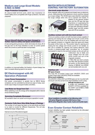
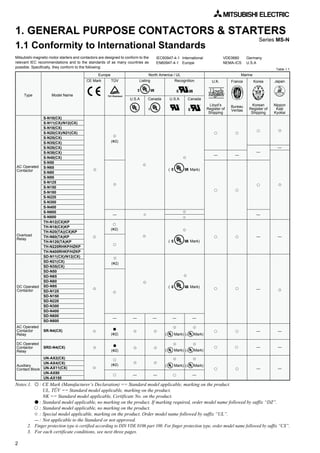
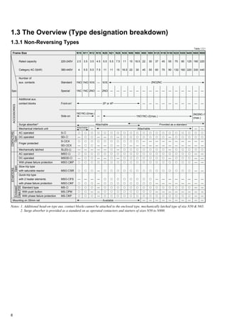
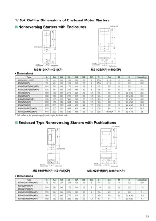
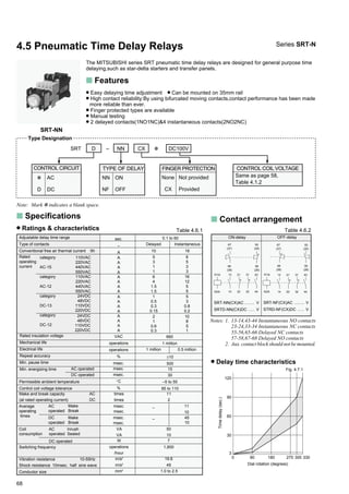
Notes: 1. UL listed types for S-N600 and S-N800 require suffix letters “UL” (eg. S-N800UL).
2. Types S-N5O to S-N800 and MSO-N50KP to N400KP with Ilsco lugs are also listed as type name with suffix letters
“UL” (eg. S-N50UL)
3. Time delay fuse
4. Class L fuse
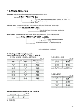
1.1.3 UL Approval for U.S.A. and Canada
s Contactor and Motor Starter
Model Name
Continuous current rating
open
Horsepower rating
Single phase
Three phase
Model Name
Horsepower rating
Three phase
Mark
Mark —
0.12A(0.1~0.16),0.17(0.14~0.22),0.24A(0.2~0.32),
0.35A(0.28~0.42),0.5A(0.4~0.6),0.7A(0.55~0.85),0.9A(0.7~1.1),
1.3A(1~1.6),1.7A(1.4~2),2.1A(1.7~2.5),2.5A(2~3),3.6A(2.8~4.4),
5A(4~6),6.6A(5.2~8),9A(7~11),11A(9~13)
Model Name
TH-N12(CX)KP✩
TH-N12(CX)✩✽1
TH-N12(CX)HZKP5✽2
TH-N12(CX)HZ5✽1
s Thermal Overload Relay
TH-N18(CX)KP✩
TH-N18(CX)✩✽1
1.3A(1~1.6),1.7(1.4~2),2.1A(1.7~2.5),2.5A(2~3),3.6A(2.8~4.4),
5A(4~6),6.6A(5.2~8),9A(7~11),11A(9~13),15A(12~18)
0.24A(0.2~0.32),0.35A(0.28~0.42),0.5A(0.4~0.6),
0.7A(0.55~0.85),0.9A(0.7~1.1),1.3A(1~1.6),1.7A(1.4~2),
2.1A(1.7~2.5),2.5A(2~3),3.6A(2.8~4.4),5A(4~6),6.6A(5.2~8),
9A(7~11),11A(9~13),15A(12~18)
TH-N20(CX)KP
TH-N20(CX)✽1
TH-N20CXHZKP5
TH-N20CXHZ5✽1
TH-N20TAKP✩
TH-N20TA✩✽1
22A(18~26)
29A(24~34)
TH-N60KP
15A(12~18),22A(18~26),29A(24~34),35A(30~40),42A(34~50)
54A(43~65)
TH-N60TAKP✩
67A(54~80)
82A(65~100)
TH-N120KP 42A(34~50),54A(43~65),67A(54~80),82A(65~100)
TH-N120TAKP✩
105A(85~125)
125A(100~150)
82A(65~100),105A(85~125),125A(100~150),150A(120~180)
180A(140~220)
TH-N220RHKP✩
TH-N220HZKP5
105A(85~125),125A(100~150),150A(120~180),180A(140~220),250A(200~300)
330A(260~400)
TH-N400RHKP✩
TH-N400HZKP5
Heater designation (Rated current [A])
Contactor to
be coupled
S-N10
S-N11
S-N12
S-N18
S-N20
S-N21
S-N25
S-N35
S-N25,N35
S-N35
S-N50,N65,N80,N95
S-N65,N80,N95
S-N80,N95
S-N95
S-N125,N150
S-N125,N150
S-N150
S-N180,N220
S-N220
S-N300,N400
S-N400
Auxiliary Contact
Rated
Code
Make
C600
AC600Vmax
1800VA(15A max)
Break 180VA(1.5A max)
Rated
Code
Make
B600
AC600Vmax
3600VA(30A max)
Break 360VA(3A max)
Notes: 1. ✩ is to be coupled with contactor and can not be mounted separately from contactor. 5 is only for separate mounting.
2. Suffix “KP” ; Overload and phase failure protection type with three heater elements.
3. ✽1 ; TH-N12(CX), N12(CX)HZ, N18(CX), N20(CX), N20CXHZ and N20TA are recognized ( ) for single phase motors.
4. ✽2 is to be coupled with TH-N12(CX)KP ( ) and UN-HZ12( ).
s Contactor Relay and
Auxiliary Contact Block
Auxiliary
Contact
Block
UN-AX2(CX)
UN-AX4(CX)
UN-AX11(CX)
UN-AX80
UN-AX150
Type
Model Name
Ratings
Rated
Code ;
A600
AC600V max
Make
7200VA
Break
720VA
Contactor
Relay
SR(D)-N4
Rated
Code ;
R300
DC250V max
Make
28VA
Break
28VA
Table 1.1.3 (1)
Table 1.1.3 (2) Table 1.1.3 (3)
/
/](https://image.slidesharecdn.com/catalog-contactor-mitsubishi-160422014628/85/Catalog-Contactor-Mitsubishi-Beeteco-com-10-320.jpg)
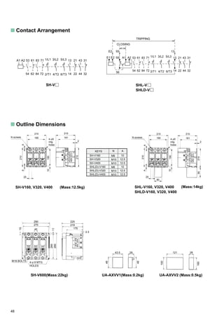
![6
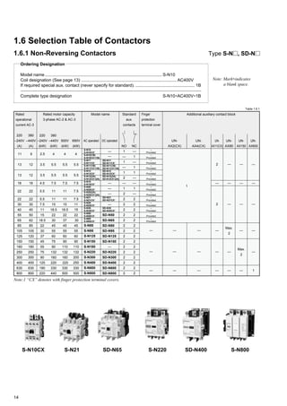
Three-phase motor
ratings IEC category
AC-3 kW(hp)
11(15)
18.5(25)
18.5(25)
15(20)
60
2NO+2NC
—
1
2
1
1
2.5(3-1/4)
4(5-1/2)
4(5-1/2)
4(5-1/2)
20
1NO
1NC
1
2
1
1
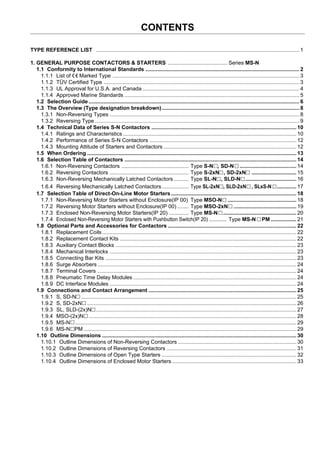
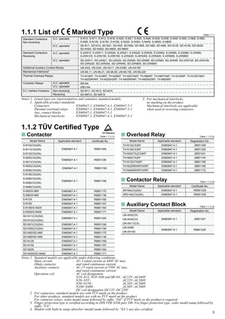
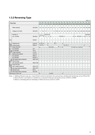
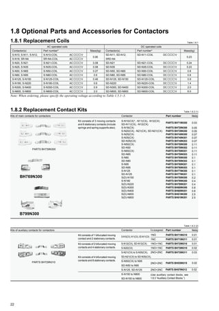
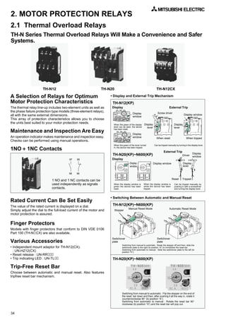
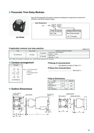
1.2 Selection Guide
220-240V
380-440V
500V
660V
1NO + 1NC (front)
1NO + 1NC (side)
2NO + 2NC (front)
Low level signal (front)
[1NO+1NC
(+Standard 1NO + 1NC)]
Conventional free air thermal current Ith A
Auxiliary contacts1
(standard)
(special)
3.5(4-1/2)
5.5(7-1/2)
5.5(7-1/2)
5.5(7-1/2)
20
1NO
1NC
1
2
1
1
3.5(4-1/2)
5.5(7-1/2)
5.5(7-1/2)
5.5(7-1/2)
20
1NO+1NC
2NO
1
—
1
1
4.5(6)
7.5(10)
7.5(10)
7.5(10)
25
–2
—
1
—
1
1
5.5(7-1/2)
11(15)
11(15)
7.5(10)
32
1NO+1NC
2NO
1
2
1
1
5.5(7-1/2)
11(15)
11(15)
7.5(10)
32
2NO+2NC
—
1
2
1
1
7.5(10)
15(20)
15(20)
11(15)
50
2NO+2NC
—
1
2
1
1
Notes: 1. Number of auxiliary contact shows that for non-reversing type. Twice of the auxiliary contacts are provided on reversing type.
2. (2NO + 2NC) × 2 auxiliary contacts are provided on reversing type and no additional contact can be mounted.
3. Front clip-on and side clip-on block should not be mounted both.
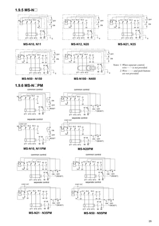
MS-N35
(KP)
MSO-N35
(KP)(CX)
S-N18(CX)
S-2xN18(CX)
—DC operated models
MS-N25
(KP)
MSO-N25
(KP)(CX)
S-N10(CX)
S-2xN10(CX)
—
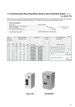
Non-reversing
Reversing
S-N11(CX)
S-2xN11(CX)
SD-N11(CX)
S-N12(CX)
—
SD-N12(CX)
S-N20(CX)
S-2xN20(CX)
—
S-N21(CX)
S-2xN21(CX)
SD-N21(CX)
S-N25(CX)
S-2xN25(CX)
—
S-N35(CX)
S-2XxN35(CX)
SD-N35(CX)
AC operated models
MS-N10
(KP)
MSO-N10
(KP)(CX)
Enclosed type (IP20) MS-N11
(KP)
MSO-N11
(KP)(CX)
MS-N20
(KP)
MSO-N20
(KP)(CX)
MS-N21
(KP)
MSO-N21
(KP)(CX)
Open type (IP00) MSO-N18
(KP)(CX)
—
Contactors
MS-N12
(KP)
MSO-N12
(KP)(CX)
Staters (AC operated)
Thermal Overload Relays1
0.2~0.32(0.24A)
0.28~0.42(0.35A)
0.4~0.6(0.5A)
0.55~0.85(0.7A)
0.7~1.1(0.9A)
1~1.6(1.3A)
1.4~2(1.7A)
1.7~2.5(2.1A)
1~1.6(1.3A)
1.4~2(1.7A)
1.7~2.5(2.1A)
2~3(2.5A)
2.8~4.4(3.6A)
4~6(5A)
5.2~8(6.6A)
7~11(9A)
9~13(11A)
12~18(15A)
Three heater type with
phase failure protection
Two heater type
Heater setting range A
(Ordering designation)
TH-N12(CX)
TH-N12KP(CX)
TH-N18(CX)
TH-N18KP(CX)
0.1~0.16(0.12A)
0.14~0.22(0.17A)
0.2~0.32(0.24A)
0.28~0.42(0.35A)
0.4~0.6(0.5A)
0.55~0.85(0.7A)
0.7~1.1(0.9A)
1~1.6(1.3A)
1.4~2(1.7A)
1.7~2.5(2.1A)
2~3(2.5A)
2.8~4.4(3.6A)
4~6(5A)
5.2~8(6.6A)
7~11(9A)
9~13(11A)2
2~3(2.5A)
2.8~4.4(3.6A)
4~6(5A)
5.2~8(6.6A)
7~11(9A)
9~13(11A)
12~18(15A)
16~22(19A)3
TH-N20(CX)
TH-N20KP(CX)
TH-N20TA(CX)
TH-N20TAKP(CX)
18~26(22A)
24~34(29A)
30~40(35A)4
Notes: 1. Saturable reactors for thermal overload relays are available as a kit or equipped with the relay. The suffix “SR” following the model
name of the relay indicates “with saturable reactor”. (ex. TH-N20KPSR*5A) (Except for type TH-N12KP, TH-N18 and TH-N18KP)
2. Except for size N10. 3. For size N20 & N21 only. 4. For size N35 only.
S-2xN11 MSO-N12 S-N21CX MSO-N35
Number of additional
auxiliary contact
block for 3
Note: 1.Products which model names are provided with suffix “CX” are provided with finger protection. (N10~N65)
Especially N10~N35 with suffix “CX” are provided with CAN terminals.
S-N11CX](https://image.slidesharecdn.com/catalog-contactor-mitsubishi-160422014628/85/Catalog-Contactor-Mitsubishi-Beeteco-com-12-320.jpg)
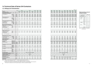
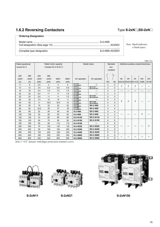
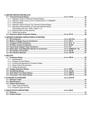
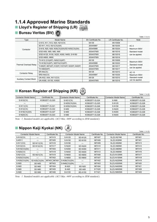
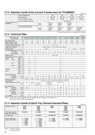
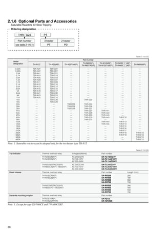
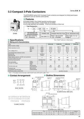
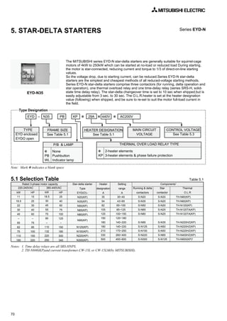
![35
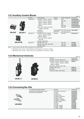
2.1.1 Selection Guide of Thermal Overload Relays
0.1-0.16
0.14-0.22
0.2-0.32
0.28-0.42
0.4-0.6
0.55-0.85
0.7-1.1
1.0-1.6
1.4-2.0
1.7-2.5
2.0-3.0
2.8-4.4
4.0-6.0
5.2-8.0
7.0-11
9.0-13
12-18
16-22
18-26
24-34
30-40
34-50
43-65
54-80
65-100
85-105
85-125
100-150
120-180
140-220
170-250
200-300
260-400
400-600
520-800
N20TA
N60TA
Table 2.1.1
Series TH-N
Max. Fuse Rating (660Vac)
IEC 269-1
(A) Heater
desig-
nation
Overload Relay
Motor Capacity [kW, (hp)]
(Three phase 50/60Hz, based on four poles)
aM gG gM AC220-240V AC380V AC400-440V AC500V
0.5
0.5
1
1
1
2
2
2
4
4
6
6
8
12
12
16
20
25
40
50
63
63
80
100
125
—
—
—
—
—
—
—
—
—
—
0.5
1
2
2
2
4
4
4
6
6
10
10
16
20
20
25
32
40
63
80
80
100
125
160
200
200
250
250
315
400
500
630
630
800
1000
—
—
—
—
—
—
—
—
—
—
—
—
—
—
—
32M35
32M50
32M63
32M63
63M80
63M80
100M100
100M125
100M160
100M200
100M200
200M250
200M250
200M315
—
—
—
—
—
—
0.12A
0.17A
0.24A
0.35A
0.5A
0.7A
0.9A
1.3A
1.7A
2.1A
2.5A
3.6A
5A
6.6A
9A
11A
15A
19A1
22A
29A
35A2
42A
54A
67A
82A
95A3
105A
125A
150A
180A
210A4
250A
330A
500A
660A
—
—
0.03(1/24)
0.05(1/16)
0.06(1/12)
0.09(1/8)
0.12(1/6)
0.18(1/4)
0.25(1/3)
0.37(1/2)
0.55(3/4)
0.75(1)
1.1(1-1/2)
1.5(2)
2.2(3)
3(4)
3.7(5)
5.5(7-1/2)
5.5(7-1/2)
7.5(10)
9(12.5)
11(15)
15(20)
18.5(25)
22(30)
30(40)
30(40)
37(50)
45(60)
55(75)
75(100)
75(100)
90(125)
110(150)
132(180)
160(220)
200(270)
220(300)
—
—
0.06(1/12)
0.09(1/8)
0.12(1.6)
0.18(1/4)
0.25(1/3)
0.37(1/2)
0.55(3/4)
0.75(1)
1.1(1-1/2)
1.5(2)
2.2(3)
3(4)
3.7(5)
4(5-1/2)
5.5(7-1/2)
7.5(10)
11(15)
11(15)
15(20)
18.5(25)
22(30)
30(40)
37(50)
45(50)
55(75)
55(75)
75(100)
90(125)
110(150)
132(180)
132(180)
160(220)
200(270)
220(300)
250(340)
300(400)
400(530)
—
—
0.06(1/12)
0.09(1/8)
0.12(1.6)
0.18(1/4)
0.25(1/3)
0.37(1/2)
0.55(3/4)
0.75(1)
—
1.1(1-1/2)
1.5(2)
2.2(3)
3,3.7(4.5)
3(4)
3.7(5)
5.5(7-1/2)
7.5(10)
9(12.5)
11(15)
11(15)
15(20)
18.5(25)
22(30)
30(40)
37(50)
45(60)
55(75)
55(75)
75(100)
90(125)
110(150)
132(180)
132(180)
160(220)
200(270)
220(300)
250(340)
300(400)
400(530)
—
—
0.09(1/8)
0.12(1/6)
0.18(1/4)
0.25(1/3)
0.37(1/2)
0.55(3/4)
0.75(1)
1.1(1-1/2)
1.5(2)
2.2(3)
3(4)
3.7(5)
5.5(7-1/2)
7.5(10)
9(12/5)
11(15)
15(20)
18.5(25)
22(30)
30(40)
37(50)
45(60)
55(75)
—
75(100)
90(125)
110(150)
132(175)
—
160(220)
220(300)
250(340)
400(530)
500(670)
Setting range
(A)
Model
(TH-)
N400
N18
N60N60
N400
N220
N600
N120TAN120
N20
N220N12
Notes: 1. For starter size N20, N21 only. 2. For starter size N35 only. 3. For starter size N95 only. 4. For starter size N220 only.
5. Selection by mounting
Notes: 1. Use “Connecting parts” when couple with contactor (see Table 2.1.6(3)). 2. W/o F/P:Without Finger Protection.
3.With F/P:With Finger Protection. 4. UN-HZ12(CX) is shipped separately from TH-N12(CX)(KP).
5. CT should be supplied by customer.
Contactor
mounting
Independent
mounting
W/o F/P
(2)
With F/P
(3)
W/o F/P
(2)
With F/P
(3)
TH-N12(KP)
TH-N12CXKP
TH-N12(KP)
+ UN-HZ12
TH-N12CXKP
+ UN-HZ12CX
TH-N18(KP)
TH-N18CXKP
—
—
TH-N20(KP)
(1)
TH-N20CXKP
(1)
TH-N20(KP)
TH-N20CXHZKP
TH-N20TA(KP)
(1)
TH-N20TAKPCX
(1)
—
—
TH-N60TA(KP)
(1)
—
—
—
TH-N120(KP)
(1)
—
TH-N120(KP)
—
TH-N120TA(KP)
(1)
—
TH-N120TAHZ(KP)
—
TH-N220RH(KP)
—
TH-N220HZ(KP)
—
—
—
TH-N600(KP)
+ CT
—
TH-N400RH(KP)
—
TH-N400HZ(KP)
—
TH-N60(KP)
(1)
TH-N60CXKP
(1)
TH-N60(KP)
TH-N60CXKP
(4)
(4)](https://image.slidesharecdn.com/catalog-contactor-mitsubishi-160422014628/85/Catalog-Contactor-Mitsubishi-Beeteco-com-40-320.jpg)
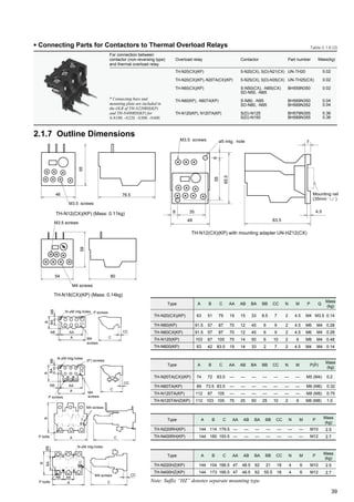
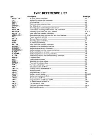
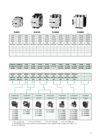
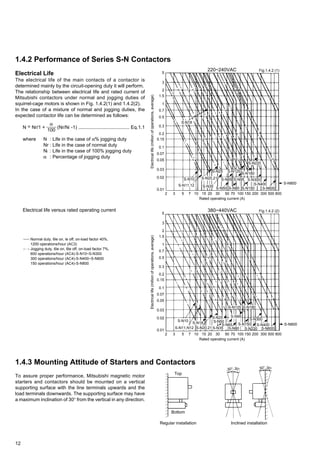
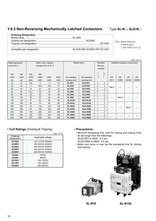
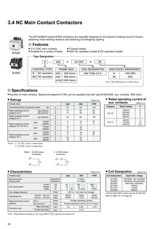
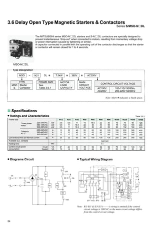
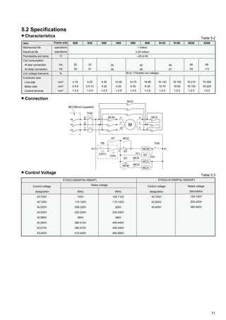
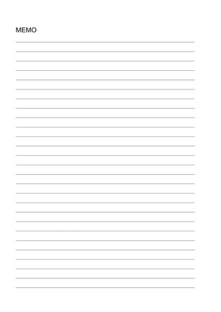
![40
2.2 Electronic Motor Protection Relays
The MITSUBISHI series ET-N relay is an excellent relay that can protect motors electrically.
Those series ET-N relays have the following excellent features.
Series ET-N
s Features
• Selectable Protection Mode
Overload (including locked rotor condition)
Phase failure (including current unbalance)
Incorrect phase sequence
• Excellent Wide Current Range
• Easy Wiring
• Easy Setting and Maintainance
• Selectable Tripping Time at 600% of setting.
Standard trip (7s.)
Quick trip (3s.)
Fast trip (5s.)
Medium trip (15s.)
Slow trip (30s.)
• Withstands High Overcurrent
• Fine Indication of Trip Mode
• Conformity to International Standards
• Can be mounted on 35mm rail (ET-N60)
ET-N60 60A
CURRENT RANGE
0.25ϳ1A
1ϳ4A
2ϳ8A
5ϳ20A
15ϳ60A
40ϳ150A
110ϳ360A
1A
4A
8A
20A
60A
150A
360A
ET - N60 ✽ 8A ✽ AC100/200V
100-120V 50/60Hz
200-240V 50/60Hz
AC100V
AC200V
FRAME SIZE
60A frame
150A frame
360A frame
N60
N150
N360
Overload
Phase failure
Reversal phase
Vibration 10-55Hz
Sine wave pulse
Main terminals
Control terminals
VAC
A
kW
kW
HP
HP
A
A
A
A
°C/%RH
VA
times
%
%
%
VAC
m/s2
m/s2
mm2
mm2
2
1
1
0.2
–10 to`55/45 to 85
7.5 (AC100V)/15 (AC200V)
0.85 to 1.1 (rated control voltage)
See Fig. 2.2.1
[minimum tripping current] 110 to 120 (at setting current)
more than 70 (at setting current) [Tripping time : 2-4 sec.]
more than 70 (at setting current) [Tripping time : less than 0.5 sec.]
2500 [1 minute]
19.6
49
1.25-2
s Specifications
Permissible ambient temperature/humidity
Control circuit consumption
Control voltage tolerance
Tripping time
Tripping condition
Withstand voltage
Shock resistance
Frame size [Current range]
Rated insulation voltage
Adjustable setting range
Applicable motor
capacity
3-ph
Rated operating
current of aux.
contacts
200-240VAC
380-440VAC
200-240VAC
380-440VAC
Category 120VAC
AC-15 240VAC
Category 24VDC
DC-13 110VDC
N60[1A]
0.25-1
0.03-0.2
0.05-0.4
1/16-1/4
1/8-1/2
N60[4A]
1-4
0.2-0.75
0.4-1.5
1/4-1
1/2-2
N60[8A]
2-8
0.4-1.5
0.75-2.2
1/2-2
1-3
N60[20A]
5-20
1.5-4
2.2-7.5
2-5
3-10
N60[60A]
15-60
3.7-11
7.5-22
5-15
10-30
N150[150A]
40-150
11-37
22-75
15-50
30-100
N360[360A]
110-360
30-90
55-150
40-125
75-200
690
2-14 3.5-22 5.5-60
Table 2.2.1• Ratings and characteristics
Conductor size
14-200
Note: ET-N relay cannot be used on DC circuit
Type Designation
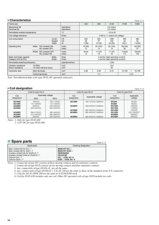
CONTROL VOLTAGE](https://image.slidesharecdn.com/catalog-contactor-mitsubishi-160422014628/85/Catalog-Contactor-Mitsubishi-Beeteco-com-45-320.jpg)
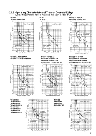
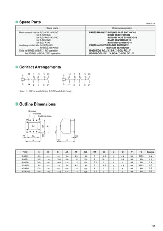
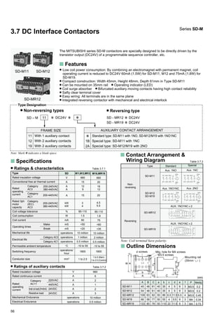
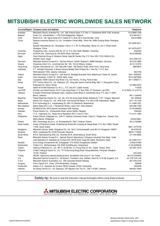
![41
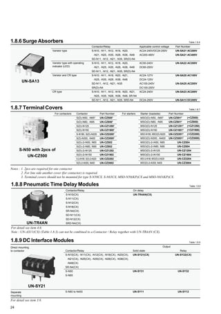
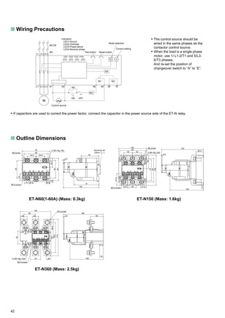
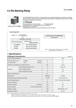
• Characteristic Curves
(h)
(s)
2
(min)
60
50
40
30
20
10
8
6
5
4
3
2
1
1
1000
800
600
400
200
100
80
60
40
30
20
10
8
6
4
2
1
0.8
0.6
0.4
0.2
0.8 1 1.5 2 3 4 5 6 8 10 15
Phase failure
Overload
Reverse phase
Multiple of Setting current
Trippingtime
(600%)
30s
15s
7s
5s
3s
Fig 2.2.1
Overload tripping time
at 600% of setting(s)
3
5
7
15
30
3
5
7
15
30
3
5
7
15
30
Symbol on changeover switch
0
1
2
3
4
5
6
7
8
9
A
B
C
D
E
Overload, phase failure and
reversal phase
[3E]
Overload and phase failure
[2E]
Overload only
[1E]
Protection mode
Table 2.2.2
• Application to High Voltage or Big Motor Circuit
The high voltage current transformer (secondary current: smaller than 5A:
capacity: more than 5VA) should be connected to ET-N60✽8A in the star
connection, when the load is high voltage or big AC motor.
Current Setting
ET-N60 MODE
0 12
345
6789A
BDC
EF
TEST RESET20A
RC.A
CURRENT
10
5 20
15
PWR OC PF REV
Function Selector
Switch
• Selection of Protection Mode & Tripping Time
The selector switch is set at position “7” (overload
and phase failure protection mode; standard trip
type) when shipping.
So please reset the position of the changeover
switch according to Table 2.2.2 before installation.](https://image.slidesharecdn.com/catalog-contactor-mitsubishi-160422014628/85/Catalog-Contactor-Mitsubishi-Beeteco-com-46-320.jpg)
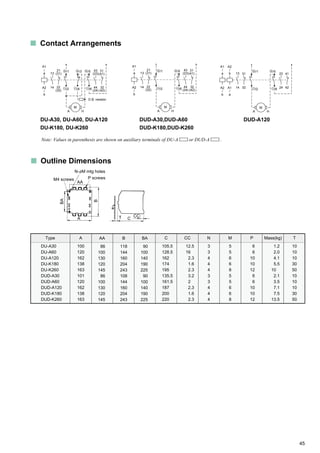
![55
Caution
1. When the circuit breaker (NF) is made (ON) and disconnected (OFF) repeatedly within a short time interval [eg: when the
instantaneous power failure occurs within a short time interval], electrical parts might be damaged or specified holding time
might not be assured.
Causes; 1) Overload occurs by frequent inrush current to RF and R1.
2) Enough electricity is not charged into the capacitor (C).
2. Even after the power is turned off (after the NF is disconnected), current might remain in the capacitor (C). So please take
care to avoid the electrical shock, when you check or repair the system.
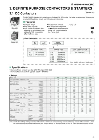
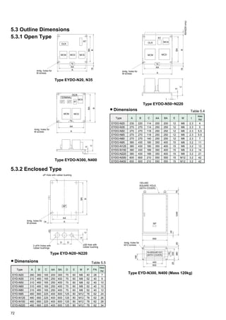
s Outline Dimensions
s Dimensions
Dimension
MSO-N12DL
MSO-N21DL
MSO-N35DL
MSO-N50/65DL
MSO-N80/95DL
MSO-N150DL
MSO-N220DL
MSO-N300/400DL
Model
132
137
134
150
170
210
230
300
40
60
50
50
100
140
140
200
ABA ADAC
49
43
42
56
35
26
20
10
69
73
67
81
85
105
90
–
B
110
125
162
168
220
270
290
361.5
100
100
150
150
200
250
250
200
BA BC
5
19
6
9
10
10
12
25
BD
12.5
11
23
26.5
39.5
33
21
30
C
98
98
114
141
165
177.5
208.5
229
CA
6
6
8
8
8
8
8
8
CB
5
5
5
10
10
30
30
50
D
M3.5
M4
M5
M6
M6
M8
M10
M12
M3.5
M3.5
M3.5
M4
M4
M4
M4
M4
3-M4
3-M4
3-M4
3-M5
3-M6
3-M8
3-M8
4-M8
Table 3.6.2
FE
Mtg hole for F Screw
AC AB
AD
D screws
E screws
CB C
CA
BDBC
C
(+)
C
(-)
MC
THR
NO/NC
P4P3P1S/3R/1
NO
R3
R3
R4
R1
R2
VARVAR
R1
(P3)
(P4)
BA
B
A
Notes: 1. Dimensions CB is the arc clearance.
2. Outline dimensions of S-N DL are the same as those of MSO-N DL, except for S-N300/N400DL. Dimension B of S-
N300/N400DL is 250mm.](https://image.slidesharecdn.com/catalog-contactor-mitsubishi-160422014628/85/Catalog-Contactor-Mitsubishi-Beeteco-com-60-320.jpg)
![61
Type Designation
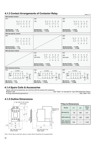
4.1.2 Auxiliary Contact Blocks
UN-AX 4 CX ✽ 2A2B
POLES
4 pole
2 pole
4
2
None
CX
Not provided
Provided
FINGER PROTECTION CONTACT
ARRANGEMENTS
See Table 4.1.4
None
CX
Not provided
Provided
FINGER PROTECTION
Front clip-on types
None
CX
Not provided
Provided
FINGER PROTECTION
[FOR LOW SIGNAL LEVEL] UN-LL22 CX
Note: Mark ✽ indicates a blank space.
Applicable contact arrangements
Rated insulation voltage
Conventional free air thermal current
Rated
operating
current
Mechanical life
Electrical life
Conductor size
Permissible ambient temperature/humidity
Switching frequency
Category AC-15
(coil load)
Category DC-13
(large coil load)
lth
Type UN-
110VAC
220VAC
440VAC
48VDC
110VDC
220VDC
operations
operations
°C/%RH
operations
/hour
mm2
A
A
A
A
A
A
V
A
6
5
3
3
0.8
0.2
690
16
1,800
1.0 to 2.5
–25 to +55/45 to 85
2.5 million
0.5 million
10 million
0.5 million
240VAC 20mA
(COSjм0.95)
48VDC 100mA
(L/RϹ1msec)
Minimum
operating current
5VDC 5mA
Note: 1. Contact reliability may be decreased if it is operated more than 1 million operations
UN-AX2 2A
UN-AX4 4A
UN-AX11
UN-AX2 1A1B
UN-AX4 3A1B
UN-AX2 2B
UN-AX4 2A2B
UN-LL22
2NC1NO+1NC
1NO+1NC, 1NO+1NC
2NO
4NO
Front
clip-on
types
Table 4.1.2 (1)
Table 4.1.2 (2)
Side clip-on types
s Ratings and characteristics
4NO
3NO+1NC
2NO+2NC
2NO
1NO+1NC
2NC
AX2 (CX) AX4 (CX)
1NO+1NC1
[Low level]
LL22 (CX)
250
1
1NO+1NC
[Standard]
AX11(CX)
INO+INC
s Selection guide & contact arrangements
62
61
52
51
64
63
52
51
6454
6353
53 63 73 83
54 64 74 84
83736153
847462543NO+1NC
83716153
847262542NO+2NC
low level
standard
81716353
82726454
Side
clip-on
types 54 62
53 61
When mount on left side
72
71
84
83
When mount on right side
UN-AX11 CX
1NO+INC
Note: Front clip-on types and side clip-on contact block should not be mounted both.](https://image.slidesharecdn.com/catalog-contactor-mitsubishi-160422014628/85/Catalog-Contactor-Mitsubishi-Beeteco-com-66-320.jpg)
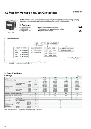
![64
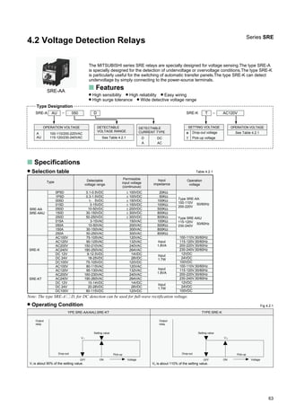
max. measurement – min. measurementNote: 1. Repetitive operation accuracy (%) = ± ×
Ratings and characteristics
Type
Output contact arrangement
Conventional free air thermal current Ith
Category
AC-15
Category
DC-13
110VAC
220VAC
24VDC
110VDC
Repetitive operation1
Control voltage fluctuation
Ambient temperature change
Response time(at 150% of the rated voltage)
Mechanical life
Electrical life
Permissible ambient temperature/humidity
Power consumption
Operation voltage tolerance (ambient temperature 40°C)
Withstand voltage
Insulation resistance (500VDC insulation tester)
Vibration resistance
Shock resistance
10 to 55Hz
10msec half sine wave
A
A
A
A
A
%
%
%
msec
operations
operations
°C/ %RH
VA
%
VAC
MΩ
m/s2
m/s2
SRE-A
±1.5
±2.5
100 to 200
10 million
0.25 million
–10 to +55/max. 85
2
85 to 110
1500 [1 minute]
min. 100
19.6
98
SRE-K
–
–
1 changeover
3
1.5
1.0
1.0
0.2
±1
max. scale value
× 100.
Table 4.2.2
s Wiring precautions
Type SRE-A Type SRE-K
SRE-AA
AC100 ~ 110V
AC200 ~ 220V
SRE-AAU
AC115 ~ 120V
AC230 ~ 240V
s Outline dimensions
Rated operating
current of output
contact
Accuracy
1
2
V1-Common
V2-Common
8
6
4
21
3
5
7V
V
2
1
Common
( ,–)
( ,+)
Power
source
Detection
~
~
7
5
3
1
8
6
4
2
Power source
& detection
Output
( ,–)
( ,+)~
~
M3.5×8
self-lifting terminal
2-4.8×6.8
mtg holes
(for M4 screws)
30
43
2
52
60
16 107
10
93(terminal heignt)
Fig 4.2.2](https://image.slidesharecdn.com/catalog-contactor-mitsubishi-160422014628/85/Catalog-Contactor-Mitsubishi-Beeteco-com-69-320.jpg)
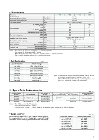
![67
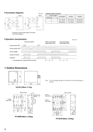
4.4 Solid State Time Delay Relays
The MITSUBISHI series SRS-H solid state time delay relays are specially designed for high
accuracy and easy mounting.
s Features
High accuracy Compact design High reliability
Easy mounting (for direct panel mounting or mounting on 35mm rail)
With finger protection (terminal cover) model is available
1 delayed & 1 instantaneous changeover contact for ON-delay relay.
Series SRS-H
s Outline Dimensions
Type Designation
ON-delay : SRS-H NP S – AC200V
S 3 sec.-30sec.
CONTROL VOLTAGE
See Table 4.5.2
DELAYING TIME
s Specifications
Table 4.5.1
Relay type
SRS-HNPS
Adjustable time range
Control voltages Table 4.5.2
Ordering
designation
AC100V
AC200V
AC400V
Rated voltage
100-120V 50/60Hz
200-240V 50/60Hz
380-440V 50/60Hz
Rating & characteristics Table 4.5.3
Type
Conventional free air thermal current
Rated
operating
current
Category
AC-15
120VAC
240VAC
440VAC
Accuracy
Minimum pause time
Mechanical life
Electrical life
Permissible ambient temperature
Permissible ambient relative humidity
Control voltage tolerance
AC
A
ON-delay
2
±0.5
±1
±5
100
10 million
0.1 million
–10 to 55
45 to 80
85 to 110 (rated control voltage)
Vibration resistance 10-55Hz
Shock resistance 10msec half sine wave
Withstand voltage [live parts to ground]
19.6
49
2000 (1 min.)
%
%
%
msec.
operations
operations
°C
%RH
%
VA
m/s2
m/s2
VAC
3 sec. - 30 sec.
Internal wiring
SRS-HNPS (Mass: 0.15kg)
ON-delay
Time delay selection
A
A
A
1.5
1
0.3
Repetitive operation
Control voltage fluctuation
Ambient temperature change
Power
consumption
Control
voltage
SRS-HNPS
22.5
M3.5 screws
6
5
97 3.5
35
75
62
2-M4
mtg. holes
12
Mounting rail
(35mm )
INPUT
(A2)
ON-delay
(18)
(24)(16)
(15) (22)
(21)(A1)
+( )
~ –( )
~
Contacts
1 delayed and
1 instantaneous
changeover
5 (AC100V/AC200V)
10 (AC400V)](https://image.slidesharecdn.com/catalog-contactor-mitsubishi-160422014628/85/Catalog-Contactor-Mitsubishi-Beeteco-com-72-320.jpg)

The document describes the features and specifications of Mitsubishi's MS-N series magnetic motor starters and contactors, highlighting their compliance with international standards such as ISO and CE. It emphasizes improvements in design, safety features, and ease of installation, including the incorporation of advanced technologies for better performance and reduced operational noise. Additionally, the document provides a comprehensive list of product options, technical data, and guidelines for selecting and using these electrical components.