Download to read offline

![OPS™ Series Encoders
Performance and Value Optical Encoder System
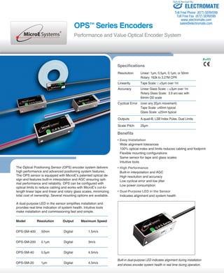
Specifications
Sold & Serviced By:
Operating and Electrical Specifications
Power Supply 5VDC +5% @ 120mA when used with
recommended termination, 80mA unterminated
Temperature
Operating 0 to 70oC
Storage -20 to 85oC
Humidity 10 to 90% RH non-condensing
Agency Standards Conformance: In accordance with Electro-magnetic
Compatibility Directive 2004/108/EC:
EN 55011:2007
EN 61000-4-2, -3, -4, -6
Shock 300G 0.5 ms half sine
Vibration 30G at 17Hz
Sensor Cable Double Shield
(contact MicroE Systems for applications >5m)
Diameter 3.6mm (0.142")
Flex Life 20x106 cycles @ 20mm bending radius
Standard 15 pin D-sub connector
Outputs
Digital A-quad-B, 1LSB index pulse, left and right limits. A, B
and I signals are differential. Limits are single ended. Index is
gated to AB high.
Signal Level
A/B/I (differential): RS-422 compatible
Limits: 3.3VDC max., LVTTL compatible (High>2.4VDC, Low
<0.4VDC), maximum current output (source and sink): 14mA
Limits programmable as active high, active low or disabled
Alarm: Tri-state of A, B and I outputs, latched for minimum 30ms
System
OPS sensors are compatible with:
- PurePrecision™ Marker Tape II and Laser Tape II
- Linear and rotary glass scales
Scale Pitch 20μm
Signal Period 20μm
System Resolution 1μm, 0.5μm, 0.1μm or 50nm
(specify at time of ordering)
Maximum Output Frequency 30 million states/sec
Accuracy/Linearity
Linearity Tape Scale: ≤ ±5μm over 1m*
Accuracy Linear Glass Scale: ≤ ±3μm over 1m
Quadrature and Index
A
B
I
Output Frequency (at maximum speed)
OPS 200/400: 7.5Mhz per channel
OPS 40: 2.25Mhz per channel
OPS 20: 1.125Mhz per channel
Note: Output frequency must not exceed maximum input frequency of customer
electronics.
* With reference to the sensor‘s optical centerline (see
interface drawings).
Limits
≥ 5mm ≥ 5mm
Left Limit Marker Right Limit Marker
0.6mm ± 0.3* 0.6mm ± 0.3*
Right Limit Out
Pin 10
Left Limit Out
Pin 11
Pins 14 & 6
Pins 13 & 5
Pins 12 & 4
Rotary Glass Scale: 3.9 arc-sec with 64mm
OD scale
Cyclical Error (over any 20μm movement)
Tape Scale: ±40nm typical
Glass Scale: ±25nm typical
*After two point correction in the customer’s controller.
Note: Accuracy is the maximum error over the specified movement when
compared to a NIST-traceable laser interferometer standard, used at room
temperature.
RoHS
Sensor Size & Weight (side mount sensor)
Height Width Length
0.46 [11.67mm] 0.56 [14.30mm] 1.35 [34.25mm]
Weight 8g (without cable)
Reliability Information
5 Year Expected Reliability >99.8% under normal operating
conditions
Digital Output Signals
Inverse signals are not shown for clarity. Active low limit configuration is shown.
ELECTROMATE
Toll Free Phone (877) SERVO98
Toll Free Fax (877) SERV099
www.electromate.com
sales@electromate.com](https://image.slidesharecdn.com/microesystemsopsdsdatasheet-141018121837-conversion-gate02/85/Micro-e-systems_ops_ds_datasheet-2-320.jpg)

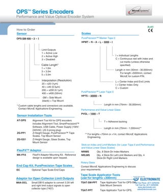
![OPS™ Series Encoders
Performance and Value Optical Encoder System
RoHS
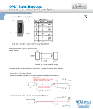
FlexFitTM Adaptor (optional)
The FlexFit adaptor for the OPS Side Mount sensor enables flexible mounting
configurations and is compatible with many industry-standard mounting hole
patterns. OPS can be installed without re-designing your system hardware.
OPS with FlexFit Adaptor - Configuration Options
OPS -SM Sensor Head
FlexFit Adaptor Plate (reversed)
(shown with mounting screws)
FlexFit Adaptor with mounting hole dimensions
(dimensions in millimeters)
FlexFit Adaptor Plate
(shown with mounting screws)
Reference drawing available. Contact MicroE Systems Application Engineering.
FlexFit Adaptor Size and Weight
Length Width Height
1.85 [47.0mm] 0.32 [8.0mm] 0.53 [13.4mm]
Weight 8g (sensor without cable)
20g (sensor with FlexFit Adaptor and mounting hardware)
Sold & Serviced By:
ELECTROMATE
Toll Free Phone (877) SERVO98
Toll Free Fax (877) SERV099
www.electromate.com
sales@electromate.com](https://image.slidesharecdn.com/microesystemsopsdsdatasheet-141018121837-conversion-gate02/85/Micro-e-systems_ops_ds_datasheet-4-320.jpg)
![OPS™ Series Encoders
Performance and Value Optical Encoder System
RoHS
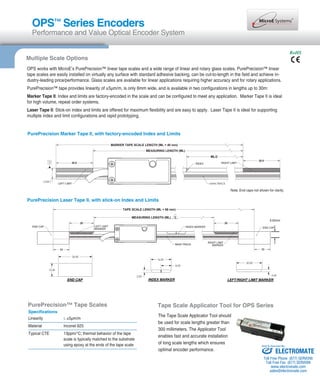
OEM Flexibility – Top Mount Configuration, High Accuracy & Multiple Scale Options
B
SENSOR MOUNTING SURFACE
TAPE SCALE MOUNTING SURFACE
Wide Alignment Tolerances
OPS Top Mount Configuration
Sensor Alignment Tolerances
Axis Alignment Tolerance
X Direction of Motion
Y ± 0.20mm
Z ± 0.15mm
θX ± 1.0°
θY ± 1.0°
θZ ± 2.0°
For OEMs that need to install OPS in extremely tight spaces or for low profile rotary axes,
MicroE also offers the OPS in a top mount configuration.
OPS can also be configured for applications that
require high accuracy and works with a range of
rotary and linear glass scales. Contact MicroE Ap-plications
C
27.00
2.50
6.75
A
C1
3.84
METAL TAPE SCALE
ADHESIVE BACKING
A
B2 B1
0.20
2.03
3.84
3.29
6.9
OPTICAL CL
B
13.70
C
2.50
2.24
9.00
13.49
21.59
4X R2.39
4X R0.76
2X 2.79 THRU. 32.00
4.95
27.00
engineering to explore OEM solutions.
OPS Series available with:
• Top mount sensor
• High accuracy linear glass scales
• Range of rotary glass scales
Z
Y
X
θz
Sensor Size & Weight (top mount sensor)
Height Width Length
0.35[8.93mm] 0.53 [13.49mm] 1.26 [32.00mm]
Weight 6g (without cable)
Dimensions for Top Mount Configuration
Sold & Serviced By:
ELECTROMATE
Toll Free Phone (877) SERVO98
Toll Free Fax (877) SERV099
www.electromate.com
sales@electromate.com](https://image.slidesharecdn.com/microesystemsopsdsdatasheet-141018121837-conversion-gate02/85/Micro-e-systems_ops_ds_datasheet-5-320.jpg)


The document describes the OPSTM Series optical encoders from Electromate. The encoders deliver high performance and value with built-in interpolation and auto gain control. They can be configured with optical limits and work with various linear and rotary scales. Installation and commissioning is fast and simple using intuitive alignment tools and software. The encoders provide high resolution, accuracy and reliability for positioning applications.


![Getting Started with Apache Spark: Big Data Made Simple [Free Meetup]](https://cdn.slidesharecdn.com/ss_thumbnails/apachesparkgettingstarted-260203175547-8361bcc3-thumbnail.jpg?width=640&height=640&fit=bounds)


