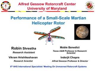
Alfred Gessow Rotorcraft Center
University of Maryland
6th AHS International Specialists’ Meeting On Unmanned Rotorcraft Systems
Robin Shrestha
Research Assistant
Inderjit Chopra
Alfred Gessow Professor & Director
Moble Benedict
Texas A&M Professor & Research
Scientist
Vikram Hrishikeshavan
Research Scientist
Performance of a Small-Scale Martian
Helicopter Rotor
Outline
• Introduction to Martian Air Vehicle
Concepts
• Selection of rotorcraft
• Performance Measurements
• Conclusions
The Need for an Aerial Vehicle for
Martian Exploration
x Limited Mobility
x Unable to reach areas of
high priority
x Limited Field of View
Limitations of Traditional
Surface Rovers:
 Removes the limitations
associated with rough terrain
 Greater speed, range, and field
of view
 Closer surveillance (than orbiter)
Advantages of an Aerial
Vehicle:
Introduction: Martian Air
Vehicle Concepts
Fixed Wing (ARES)Lighter than Air Rotary (MARV)
x Highest Power Consumption
 Take off and Land Vertically
 Hover/low speed capability
 Precision control to collect
samples and deliver sensors
 Low Power Consumption
x Unrealistic Size
x No Control Authority
 Good Endurance/ efficient
x High Speed (> 100 m/s)
x Not re-useable
Martian Rotorcraft
Martian Micro Rotorcraft
Can a micro rotorcraft hover
(at least 10 grams payload) on Mars ?
Key Questions
x (>100 m)
Can it perform a useful mission?
What is suitable platform (coaxial, quad etc) ?
Martian Micro Rotorcraft
(Feasibility Study for NASA-JPL)
Design drivers
• Air density (Mars) = (1/70) X Air density (Earth)
• Speed of sound (Mars) = 0.72 X Speed of sound (Earth)
• Gravity (Mars) = 0.37 X Gravity (Earth)
Rotor Design: Challenges
• High rotor rotational speeds
• High mach number + Low Reynolds number
• Poor airfoil performance (low rotor efficiency)
• Low endurance
Design Solution
• Scaling up rotor radius (to improve efficiency and reduce
mach number)
• Higher blade chord (increases Reynolds number)
• Optimized blade airfoil, twist and planform
• Is it feasible to hover on Mars?
• If yes, can we have a realistic endurance?
Mass < 1 Kg
Experimental Setup
Evacuation Chamber
Closer look at Evacuation Chamber
Thrust
sensor
Torque
sensor
RPM
sensor
Martian density = 0.0167 Kg/m3
3 ft
3 ft
Final Rotor Hover Test Stand
Torque
Load
Linear
Bearing
Circular Ball
Bearing
Load Cell
Torque Cell
Goal:
 Measure Thrust
 Measure Torque
 RPM
 Power = Torque x RPM
Rotor Hover Test Stand Inside
Evacuation Chamber
Rotor Hover-Test Stand Evacuation Chamber
Rotor diameter = 1.5 ft
(full-scale rotor)
Proposed vehicle design:
Coaxial helicopter (mass = 200 grams, rotor diameter = 1.5 ft)
Target thrust = 0.38 N per rotor
Thrust
sensor
Torque
sensor
RPM
sensor
Martian density = 0.0167 Kg/m3
Challenge: Matching Martian
Atmospheric Density
Pressure Sensor
Thrust
sensor
𝝆 =
𝒑
𝑹 𝒔𝒑𝒆𝒄𝒊𝒇𝒊𝒄 𝑻
𝑴𝑨𝑹𝑻𝑰𝑨𝑵 𝝆= 0.0167
𝐾𝑔
𝑚3
Extensive Calibration with
pressure sensor
Focused calibration to narrow
range of pressures
Thermocouple (SA2C-k)
Factory default cold
junction compensation
value
Verified with thermometer
CDAQ System
National Instruments CDAQ
Board
Thrust
sensor
Torque
sensor
Load Cell (SCC-SG24)
Torque Cell (SCC-SG24)
Thermocouple (SCC-TC02)
Hall Sensor
Pressure Sensor
Blade Fabrication Process
Best Performing Airfoils From Previous Study
(Best performing out of 30 different airfoils tested)
Wortmann FX 63-100
NACA M10
ARA-D 6%
AH-7-47-6
Selig-1223
Cambered thin plate
Eppler-63
NACA 0012
NACA 6504
All rotors were rapid-prototyped except cambered thin plate
Carbon fiber for stiffness
Low-speed
airfoils
Step 1: Mold Blades
Target Circular Camber = 6% - 7%
Height of an Arc Segment:
Height =
Height = 0.1270 in
Camber:
Camber=
Camber = 6.35 %
8 in diameter circular mold
Chord = 2 in
Height
Step 1: Mold Blades
(continued)
Rotor diameter = 1.5 ft
(full-scale rotor)
Blade mold machined from 8 in diameter circular plate
3 layers of carbon fiber heated at 350° F
Step 2: Mill Blades
1/8 in drill-bit
3 layers molded carbon fiber
sheets
Milling Machine
3D printed cambered
base
 Blade planforms drawn on AutoCad
 Blades milled out with milling
machine
 Precision accurate ± 0.001 inches
Rectangular Baseline Rotor
𝑿 𝑪𝑮
𝑪 𝒓 = 𝑪 𝒕 = 2in
𝑺𝒑𝒂𝒏 = 𝟖. 𝟐𝟓 𝒊𝒏
Additional Steps:
Sharpen Leading Edge
Balance Rotor
Rotor Hub Fabrication Process
3D CAD Drawing
Example 24° Root Collective Pitch Rotor Hub:
24°
3D Printed
Top View:
Side View:
Low Pitch 10° Med Pitch 24° High Pitch 38°
Range of Collective Pitch Angles
Collective Pitch Angle Range: 10° – 40°
Rotor Blade in Rotor Hub
Top View (Rectangular Rotor on 34° hub): Side View:
34°
Performance Measurements
(Tip Reynolds number ~ 3,300)
Systematically Tested Range of
Collective Pitch Angles
𝝆= 0.0167
𝐾𝑔
𝑚3 (MARTIAN Density)
34˚
36˚
38˚
40˚
Thrust vs. RPM
30˚
18˚
24˚
28˚
26˚
40˚
18˚
24˚
26˚
28˚
30˚
34˚
36˚
38˚
Power vs. RPM
CT vs. Pitch &
CP vs. Ptch
𝝆= 0.0167
𝐾𝑔
𝑚3 (MARTIAN Density)
Rectangular Rotor Planform
4000 RPM (Tip Re ~ 4,100)
Figure of Merit
Flow model for momentum theory:
Disk area A Rotor Disk Plane
Thrust, 𝑻
𝒗𝒊
Weight
𝒅 𝒔
→ 𝒅 𝒔
→
𝒘𝒂𝒌𝒆
Figure of Merit =
𝑰𝒅𝒆𝒂𝒍 𝑷𝒐𝒘𝒆𝒓 𝑹𝒆𝒒𝒖𝒊𝒓𝒆𝒅 𝒕𝒐 𝑯𝒐𝒗𝒆𝒓
𝑨𝒄𝒕𝒖𝒂𝒍 𝑷𝒐𝒘𝒆𝒓 𝑹𝒆𝒒𝒖𝒊𝒓𝒆𝒅 𝒕𝒐 𝑯𝒐𝒗𝒆𝒓
< 1
𝑪 𝒕=
𝑻
𝝆 𝑨Ω 𝟐 𝑹 𝟐
𝑪 𝒑=
𝑷
𝝆 𝑨Ω 𝟑 𝑹 𝟑
(Formal
Definitions)
𝑪 𝒑,𝒊𝒅𝒆𝒂𝒍 =
𝑪 𝒕
3/2
2
𝑪 𝒑,𝒎𝒆𝒂𝒔𝒖𝒓𝒆𝒅
Assumptions:
Uniform inflow
No viscous losses
Non ideal effects (viscous losses)
∞
𝟎
Typical Figure of Merit Values
Re < 𝟓 × 𝟏𝟎 𝟑
Full Scale Helicopters
Re > 𝟓 × 𝟏𝟎 𝟔
Typical FM= 0.7-0.8 Typical FM=?
MAV Scale Helicopters Mars Micro Helicopter
Re ~ 𝟓 × 𝟏𝟎 𝟔
Typical FM~0.6
Optimum Pitch Angle
Baseline Rectangular Rotor Planform
4000 RPM (Tip Re ~ 4,100)𝝆= 0.0167
𝐾𝑔
𝑚3 (MARTIAN Density)
FM vs. Ct/Sigma
3200 RPM (Tip Re ~ 3,500)
30˚ Rectangular Planform
RPM Sweep Experiment Results
𝝆= 0.0167
𝐾𝑔
𝑚3 (MARTIAN Density)
Thrust vs. RPM Power vs. RPM
Could 30˚ Rectangular Rotor
Produce Enough Thrust
Power Loading vs. Thrust
PL= 0.0429 N/W at operating T = 0.38 N
Li-Po battery energy density
0 200 400 600 800 1000 1200
0
50
100
150
200
Battery Weight (g)
BatteryElectricalEnergy(W-Hr)
y = 0.1589x
(Variation of battery electrical energy vs. battery mass from commercial manufacturer data)
Endurance on Mars with
30˚ Rectangular Rotor
• Total thrust from 2 rotors = 0.76 Newton
• Mechanical power loading = 0.0429 N/W (from experiment)
• Mechanical power required = 17.716 W
• Electrical power required = 18.716/(0.5) = 35.43 W
– Assuming 50% motor efficiency
• Battery mass = 50 grams (33% of empty weight)
• Battery energy = battery mass X 0.1589 = 7.94 W-hr
• Endurance = 13.45 minutes
– Predicted endurance was around 12 – 13 minutes (2 min lost
from extrapolated prediction)
200 gram coaxial helicopter
Performance Measurements
(Varying Tip Reynolds number
3,300 - 35,000)
Reynolds Number Variation
Experiment
Constant 3200 RPM
26° Pitch Rectangular Rotor
Increasing Reynolds Number
Martian Air Density
Reynolds Number Variation
Rectangular AoA Sweep
3200 RPM (Tip Re ~ 3,300)
Increasing
Reynolds Number 𝝆= 0.0167
𝐾𝑔
𝑚3
(MARTIAN Density)
Density Variation
Rectangular AoA Sweep
3200 RPM (Tip Re ~ 3,300)
Max FM vs. Reynolds Number Optimum Pitch vs. Reynolds Number
Conclusions
• Baseline Rectangular Planform Rotor (2 in chord) has an
acceptable endurance on Mars
– Predicted Endurance on Mars ~ 13 minutes
– However FM is significantly lower (FM < 0.4) than full scale helicopter or
even a MAV-scale helicopter
• Scalability tests showed that performance significantly
improves with higher Reynolds numbers
– FM eventually reaches 0.62, which is a typical value at MAV-scale
Reynolds numbers for the present rotor design
Future studies will involve parametrically evaluating different rotor design parpmeters, which
include blade airfoil, planform shape, twist, rotor solidity at Martian air density
Thank You

ROBIN_SHRESTHA_AHS_PresentationV3

  • 1.
    Alfred Gessow RotorcraftCenter University of Maryland 6th AHS International Specialists’ Meeting On Unmanned Rotorcraft Systems Robin Shrestha Research Assistant Inderjit Chopra Alfred Gessow Professor & Director Moble Benedict Texas A&M Professor & Research Scientist Vikram Hrishikeshavan Research Scientist Performance of a Small-Scale Martian Helicopter Rotor
  • 2.
    Outline • Introduction toMartian Air Vehicle Concepts • Selection of rotorcraft • Performance Measurements • Conclusions
  • 3.
    The Need foran Aerial Vehicle for Martian Exploration x Limited Mobility x Unable to reach areas of high priority x Limited Field of View Limitations of Traditional Surface Rovers:  Removes the limitations associated with rough terrain  Greater speed, range, and field of view  Closer surveillance (than orbiter) Advantages of an Aerial Vehicle:
  • 4.
    Introduction: Martian Air VehicleConcepts Fixed Wing (ARES)Lighter than Air Rotary (MARV) x Highest Power Consumption  Take off and Land Vertically  Hover/low speed capability  Precision control to collect samples and deliver sensors  Low Power Consumption x Unrealistic Size x No Control Authority  Good Endurance/ efficient x High Speed (> 100 m/s) x Not re-useable
  • 5.
  • 6.
    Martian Micro Rotorcraft Cana micro rotorcraft hover (at least 10 grams payload) on Mars ? Key Questions x (>100 m) Can it perform a useful mission? What is suitable platform (coaxial, quad etc) ?
  • 7.
    Martian Micro Rotorcraft (FeasibilityStudy for NASA-JPL) Design drivers • Air density (Mars) = (1/70) X Air density (Earth) • Speed of sound (Mars) = 0.72 X Speed of sound (Earth) • Gravity (Mars) = 0.37 X Gravity (Earth) Rotor Design: Challenges • High rotor rotational speeds • High mach number + Low Reynolds number • Poor airfoil performance (low rotor efficiency) • Low endurance Design Solution • Scaling up rotor radius (to improve efficiency and reduce mach number) • Higher blade chord (increases Reynolds number) • Optimized blade airfoil, twist and planform • Is it feasible to hover on Mars? • If yes, can we have a realistic endurance? Mass < 1 Kg
  • 8.
  • 9.
    Evacuation Chamber Closer lookat Evacuation Chamber Thrust sensor Torque sensor RPM sensor Martian density = 0.0167 Kg/m3 3 ft 3 ft
  • 10.
    Final Rotor HoverTest Stand Torque Load Linear Bearing Circular Ball Bearing Load Cell Torque Cell Goal:  Measure Thrust  Measure Torque  RPM  Power = Torque x RPM
  • 11.
    Rotor Hover TestStand Inside Evacuation Chamber Rotor Hover-Test Stand Evacuation Chamber Rotor diameter = 1.5 ft (full-scale rotor) Proposed vehicle design: Coaxial helicopter (mass = 200 grams, rotor diameter = 1.5 ft) Target thrust = 0.38 N per rotor Thrust sensor Torque sensor RPM sensor Martian density = 0.0167 Kg/m3
  • 12.
    Challenge: Matching Martian AtmosphericDensity Pressure Sensor Thrust sensor 𝝆 = 𝒑 𝑹 𝒔𝒑𝒆𝒄𝒊𝒇𝒊𝒄 𝑻 𝑴𝑨𝑹𝑻𝑰𝑨𝑵 𝝆= 0.0167 𝐾𝑔 𝑚3 Extensive Calibration with pressure sensor Focused calibration to narrow range of pressures Thermocouple (SA2C-k) Factory default cold junction compensation value Verified with thermometer
  • 13.
    CDAQ System National InstrumentsCDAQ Board Thrust sensor Torque sensor Load Cell (SCC-SG24) Torque Cell (SCC-SG24) Thermocouple (SCC-TC02) Hall Sensor Pressure Sensor
  • 14.
  • 15.
    Best Performing AirfoilsFrom Previous Study (Best performing out of 30 different airfoils tested) Wortmann FX 63-100 NACA M10 ARA-D 6% AH-7-47-6 Selig-1223 Cambered thin plate Eppler-63 NACA 0012 NACA 6504 All rotors were rapid-prototyped except cambered thin plate Carbon fiber for stiffness Low-speed airfoils
  • 16.
    Step 1: MoldBlades Target Circular Camber = 6% - 7% Height of an Arc Segment: Height = Height = 0.1270 in Camber: Camber= Camber = 6.35 % 8 in diameter circular mold Chord = 2 in Height
  • 17.
    Step 1: MoldBlades (continued) Rotor diameter = 1.5 ft (full-scale rotor) Blade mold machined from 8 in diameter circular plate 3 layers of carbon fiber heated at 350° F
  • 18.
    Step 2: MillBlades 1/8 in drill-bit 3 layers molded carbon fiber sheets Milling Machine 3D printed cambered base  Blade planforms drawn on AutoCad  Blades milled out with milling machine  Precision accurate ± 0.001 inches
  • 19.
    Rectangular Baseline Rotor 𝑿𝑪𝑮 𝑪 𝒓 = 𝑪 𝒕 = 2in 𝑺𝒑𝒂𝒏 = 𝟖. 𝟐𝟓 𝒊𝒏 Additional Steps: Sharpen Leading Edge Balance Rotor
  • 20.
  • 21.
    3D CAD Drawing Example24° Root Collective Pitch Rotor Hub: 24°
  • 22.
    3D Printed Top View: SideView: Low Pitch 10° Med Pitch 24° High Pitch 38°
  • 23.
    Range of CollectivePitch Angles Collective Pitch Angle Range: 10° – 40°
  • 24.
    Rotor Blade inRotor Hub Top View (Rectangular Rotor on 34° hub): Side View: 34°
  • 25.
  • 26.
    Systematically Tested Rangeof Collective Pitch Angles 𝝆= 0.0167 𝐾𝑔 𝑚3 (MARTIAN Density) 34˚ 36˚ 38˚ 40˚ Thrust vs. RPM 30˚ 18˚ 24˚ 28˚ 26˚ 40˚ 18˚ 24˚ 26˚ 28˚ 30˚ 34˚ 36˚ 38˚ Power vs. RPM
  • 27.
    CT vs. Pitch& CP vs. Ptch 𝝆= 0.0167 𝐾𝑔 𝑚3 (MARTIAN Density) Rectangular Rotor Planform 4000 RPM (Tip Re ~ 4,100)
  • 28.
    Figure of Merit Flowmodel for momentum theory: Disk area A Rotor Disk Plane Thrust, 𝑻 𝒗𝒊 Weight 𝒅 𝒔 → 𝒅 𝒔 → 𝒘𝒂𝒌𝒆 Figure of Merit = 𝑰𝒅𝒆𝒂𝒍 𝑷𝒐𝒘𝒆𝒓 𝑹𝒆𝒒𝒖𝒊𝒓𝒆𝒅 𝒕𝒐 𝑯𝒐𝒗𝒆𝒓 𝑨𝒄𝒕𝒖𝒂𝒍 𝑷𝒐𝒘𝒆𝒓 𝑹𝒆𝒒𝒖𝒊𝒓𝒆𝒅 𝒕𝒐 𝑯𝒐𝒗𝒆𝒓 < 1 𝑪 𝒕= 𝑻 𝝆 𝑨Ω 𝟐 𝑹 𝟐 𝑪 𝒑= 𝑷 𝝆 𝑨Ω 𝟑 𝑹 𝟑 (Formal Definitions) 𝑪 𝒑,𝒊𝒅𝒆𝒂𝒍 = 𝑪 𝒕 3/2 2 𝑪 𝒑,𝒎𝒆𝒂𝒔𝒖𝒓𝒆𝒅 Assumptions: Uniform inflow No viscous losses Non ideal effects (viscous losses) ∞ 𝟎
  • 29.
    Typical Figure ofMerit Values Re < 𝟓 × 𝟏𝟎 𝟑 Full Scale Helicopters Re > 𝟓 × 𝟏𝟎 𝟔 Typical FM= 0.7-0.8 Typical FM=? MAV Scale Helicopters Mars Micro Helicopter Re ~ 𝟓 × 𝟏𝟎 𝟔 Typical FM~0.6
  • 30.
    Optimum Pitch Angle BaselineRectangular Rotor Planform 4000 RPM (Tip Re ~ 4,100)𝝆= 0.0167 𝐾𝑔 𝑚3 (MARTIAN Density)
  • 31.
    FM vs. Ct/Sigma 3200RPM (Tip Re ~ 3,500)
  • 32.
    30˚ Rectangular Planform RPMSweep Experiment Results 𝝆= 0.0167 𝐾𝑔 𝑚3 (MARTIAN Density) Thrust vs. RPM Power vs. RPM
  • 33.
    Could 30˚ RectangularRotor Produce Enough Thrust Power Loading vs. Thrust PL= 0.0429 N/W at operating T = 0.38 N
  • 34.
    Li-Po battery energydensity 0 200 400 600 800 1000 1200 0 50 100 150 200 Battery Weight (g) BatteryElectricalEnergy(W-Hr) y = 0.1589x (Variation of battery electrical energy vs. battery mass from commercial manufacturer data)
  • 35.
    Endurance on Marswith 30˚ Rectangular Rotor • Total thrust from 2 rotors = 0.76 Newton • Mechanical power loading = 0.0429 N/W (from experiment) • Mechanical power required = 17.716 W • Electrical power required = 18.716/(0.5) = 35.43 W – Assuming 50% motor efficiency • Battery mass = 50 grams (33% of empty weight) • Battery energy = battery mass X 0.1589 = 7.94 W-hr • Endurance = 13.45 minutes – Predicted endurance was around 12 – 13 minutes (2 min lost from extrapolated prediction) 200 gram coaxial helicopter
  • 36.
    Performance Measurements (Varying TipReynolds number 3,300 - 35,000)
  • 37.
    Reynolds Number Variation Experiment Constant3200 RPM 26° Pitch Rectangular Rotor Increasing Reynolds Number Martian Air Density
  • 38.
    Reynolds Number Variation RectangularAoA Sweep 3200 RPM (Tip Re ~ 3,300) Increasing Reynolds Number 𝝆= 0.0167 𝐾𝑔 𝑚3 (MARTIAN Density)
  • 39.
    Density Variation Rectangular AoASweep 3200 RPM (Tip Re ~ 3,300) Max FM vs. Reynolds Number Optimum Pitch vs. Reynolds Number
  • 40.
    Conclusions • Baseline RectangularPlanform Rotor (2 in chord) has an acceptable endurance on Mars – Predicted Endurance on Mars ~ 13 minutes – However FM is significantly lower (FM < 0.4) than full scale helicopter or even a MAV-scale helicopter • Scalability tests showed that performance significantly improves with higher Reynolds numbers – FM eventually reaches 0.62, which is a typical value at MAV-scale Reynolds numbers for the present rotor design Future studies will involve parametrically evaluating different rotor design parpmeters, which include blade airfoil, planform shape, twist, rotor solidity at Martian air density
  • 41.