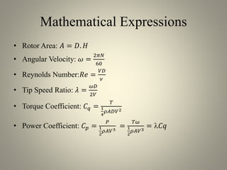
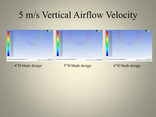
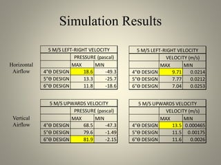
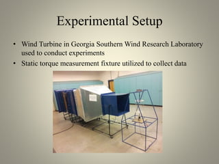
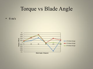
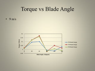
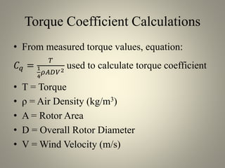
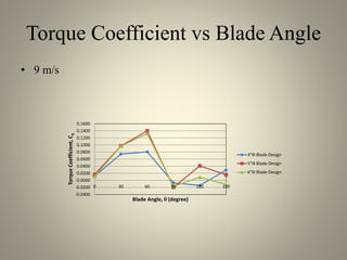
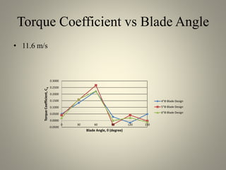
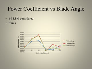
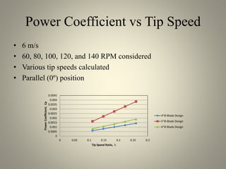
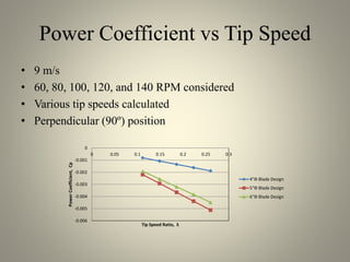
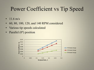
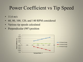
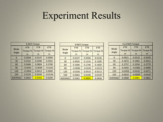
SlideShare a Scribd company logo
STATIC TORQUE ANALYSIS OF
VARIOUS TWO-BLADED
SAVONIUS WIND TURBINE
MODELS
Brandon Byrnes
brandonrbyrnes@gmail.com
Purpose of Research
• Determine the most efficient wind turbine design when
considering a specific type with only one variable
• Designs chosen were two-blade vertical axis wind turbines
with the same diameter
• Variable tested was diameter of the curved blades
Wind Turbines
• Used to convert naturally occurring wind into electric power
• Blades mounted around a central axis capture the wind
• Captured wind causes the turbines to rotate
• Two types of wind turbines: horizontal axis wind turbines and
vertical axis wind turbines
Turbine Designs Studied
• Vertical axis wind turbine
• Savonius, two-bladed design
• Blades of different radii
– 4” diameter
– 5” diameter
– 6” diameter
List of Symbols
• Symbol Explanation
• A Rotor Area
• D Overall Rotor Diameter
• d Blade Diameter
• H Rotor Height
• V Wind Velocity (m/s)
• N Revolutions Per Minute
• ν Kinematic Viscosity (m2/s)
• ρ Air Density (kg/m3)
• ω Angular Velocity (rad/sec)
• Re Reynolds Number
• λ Tip Speed Ratio
• T Torque
• P Power
• Cq Torque Coefficient
• Cp Power Coefficient
Mathematical Expressions
• Rotor Area: 𝐴 = 𝐷. 𝐻
• Angular Velocity: 𝜔 =
2𝜋𝑁
60
• Reynolds Number:𝑅𝑒 =
𝑉𝐷
𝜈
• Tip Speed Ratio: 𝜆 =
𝜔𝐷
2𝑉
• Torque Coefficient: 𝐶 𝑞 =
𝑇
1
4
𝜌𝐴𝐷𝑉2
• Power Coefficient: 𝐶 𝑝 =
𝑃
1
2
𝜌𝐴𝑉3
=
𝑇𝜔
1
2
𝜌𝐴𝑉3
= 𝐶𝑞
Procedure
• Two-part study
– ANSYS Fluent to simulate designs
– Wind tunnel to measure torque
Static Simulation
• Conduct in a 2D format
• Designs created in Geometry function as cross-section
• Sketches imported into Mesh function
• Mesh imported into Fluent function
• Simulation executed in vertical and horizontal airflow
Mesh Created
4”ϴ blade design 5”ϴ blade design 6”ϴ blade design
5 m/s Vertical Airflow Pressure
4”ϴ blade design 5”ϴ blade design 6”ϴ blade design
5 m/s Horizontal Airflow Pressure
4”ϴ blade design 5”ϴ blade design 6”ϴ blade design
5 m/s Vertical Airflow Velocity
4”ϴ blade design 5”ϴ blade design 6”ϴ blade design
5 m/s Horizontal Airflow Velocity
4”ϴ blade design 5”ϴ blade design 6”ϴ blade design
Simulation Results
Horizontal
Airflow
Vertical
Airflow
MAX MIN
4"ϴ DESIGN 18.6 -49.3
5"ϴ DESIGN 13.3 -25.7
6"ϴ DESIGN 11.8 -18.6
5 M/S LEFT-RIGHT VELOCITY
PRESSURE (pascal)
MAX MIN
4"ϴ DESIGN 9.71 0.0214
5"ϴ DESIGN 7.77 0.0212
6"ϴ DESIGN 7.04 0.0253
5 M/S LEFT-RIGHT VELOCITY
VELOCITY (m/s)
MAX MIN
4"ϴ DESIGN 68.5 -47.3
5"ϴ DESIGN 79.6 -1.49
6"ϴ DESIGN 81.9 -2.15
5 M/S UPWARDS VELOCITY
PRESSURE (pascal)
MAX MIN
4"ϴ DESIGN 13.5 0.000465
5"ϴ DESIGN 11.5 0.00175
6"ϴ DESIGN 11.6 0.0026
5 M/S UPWARDS VELOCITY
VELOCITY (m/s)
Experimental Setup
• Wind Turbine in Georgia Southern Wind Research Laboratory
used to conduct experiments
• Static torque measurement fixture utilized to collect data
Models Tested
• Models of 4”, 5”, and 6” diameter blades created
• Common 8 ½” overall diameter and 12” blade height
• Clear acrylic material construction
4”ϴ blade design 5”ϴ blade design 6”ϴ blade design
Data Acquisition
• Airflow rates of 6, 9, and 11.6 meters per second
– Calculated using anemometer
• Reynolds numbers calculated; indicate turbulent flow
• Rotational positions at 30º increments tested
• Torque measurement gathered at all wind speeds
Torque vs Blade Angle
• 6 m/s
-0.1
-0.08
-0.06
-0.04
-0.02
0
0.02
0.04
0.06
0.08
0.1
0 30 60 90 120 150
Torque,T(N-m)
Blade Angle,  (degree)
4"ϴ Blade Design
5"ϴ Blade Design
6"ϴ Blade Design
Torque vs Blade Angle
• 9 m/s
-0.05
0
0.05
0.1
0.15
0.2
0 30 60 90 120 150
Torque,T(N-m)
Blade Angle,  (degree)
4"ϴ Blade Design
5"ϴ Blade Design
6"ϴ Blade Design
Torque vs Blade Angle
• 11.6 m/s
-0.1
-0.05
0
0.05
0.1
0.15
0.2
0.25
0.3
0.35
0.4
0 30 60 90 120 150
Torque,T(N-m)
Blade Angle,  (degree)
4"ϴ Blade Design
5"ϴ Blade Design
6"ϴ Blade Design
Torque Coefficient Calculations
• From measured torque values, equation:
𝐶 𝑞 =
𝑇
1
4
𝜌𝐴𝐷𝑉2
used to calculate torque coefficient
• T = Torque
• ρ = Air Density (kg/m3)
• A = Rotor Area
• D = Overall Rotor Diameter
• V = Wind Velocity (m/s)
Torque Coefficient vs Blade Angle
• 6 m/s
-0.0800
-0.0600
-0.0400
-0.0200
0.0000
0.0200
0.0400
0.0600
0.0800
0 30 60 90 120 150
TorqueCoefficient
Blade Angle
4"ϴ Blade Design
5"ϴ Blade Design
6"ϴ Blade Design
Torque Coefficient vs Blade Angle
• 9 m/s
-0.0400
-0.0200
0.0000
0.0200
0.0400
0.0600
0.0800
0.1000
0.1200
0.1400
0.1600
0 30 60 90 120 150
TorqueCoefficient,Cq
Blade Angle,  (degree)
4"ϴ Blade Design
5"ϴ Blade Design
6"ϴ Blade Design
Torque Coefficient vs Blade Angle
• 11.6 m/s
-0.0500
0.0000
0.0500
0.1000
0.1500
0.2000
0.2500
0.3000
0 30 60 90 120 150
TorqueCoefficient,Cq
Blade Angle,  (degree)
4"ϴ Blade Design
5"ϴ Blade Design
6"ϴ Blade Design
Angular Velocity Calculations
• Revolutions per minute values of 60, 80, 100,
120, and 140 implemented to calculate power
coefficient
• Equation: 𝜔 =
2𝜋𝑁
60
used to calculate angular
velocity
• N = revolutions per minute
Tip Speed Ratio Calculations
• From calculated angular velocity values,
equation: 𝜆 =
𝜔𝐷
2𝑉
used to calculate tip speed
ratio
• 𝜔 = Angular Velocity (rad/sec)
• 𝐷 = Overall Rotor Diameter
• 𝑉 = Wind Speed Velocity (m/s)
Power Coefficient Calculations
• From calculated torque coefficient values,
equation:𝐶 𝑝 = 𝐶𝑞 used to calculate power
coefficient
•  = Tip Speed Ratio
• 𝐶𝑞 = Torque Coefficient
Power Coefficient vs Blade Angle
• 60 RPM considered
– Similar power coefficients
– Variable wind speed
Power Coefficient vs Blade Angle
• 60 RPM considered
• 6 m/s
-0.0100
-0.0080
-0.0060
-0.0040
-0.0020
0.0000
0.0020
0.0040
0.0060
0.0080
0.0100
0 30 60 90 120 150
PowerCoefficient,Cp
Blade Angle,  (degree)
4"ϴ Blade Design
5"ϴ Blade Design
6"ϴ Blade Design
Power Coefficient vs Blade Angle
• 60 RPM considered
• 9 m/s
-0.0040
-0.0020
0.0000
0.0020
0.0040
0.0060
0.0080
0.0100
0.0120
0.0140
0.0160
0.0180
0 30 60 90 120 150
PowerCoefficient,Cp
Blade Angle,  (degree)
4"ϴ Blade Design
5"ϴ Blade Design
6"ϴ Blade Design
Power Coefficient vs Blade Angle
• 60 RPM considered
• 11.6 m/s
-0.0100
-0.0050
0.0000
0.0050
0.0100
0.0150
0.0200
0.0250
0.0300
0.0350
0 30 60 90 120 150
PowerCoefficient,Cp
Blade Angle,  (degree)
4"ϴ Blade Design
5"ϴ Blade Design
6"ϴ Blade Design
Power Coefficient vs Tip Speed
• 6 m/s
• 60, 80, 100, 120, and 140 RPM considered
• Various tip speeds calculated
• Parallel (0º) position
0
0.0005
0.001
0.0015
0.002
0.0025
0.003
0.0035
0.004
0.0045
0 0.05 0.1 0.15 0.2 0.25 0.3
PowerCoefficient,Cp
Tip Speed Ratio, λ
4"ϴ Blade Design
5"ϴ Blade Design
6"ϴ Blade Design
Power Coefficient vs Tip Speed
• 6 m/s
• 60, 80, 100, 120, and 140 RPM considered
• Various tip speeds calculated
• Perpendicular (90º) position
-0.0025
-0.002
-0.0015
-0.001
-0.0005
0
0 0.05 0.1 0.15 0.2 0.25 0.3
PowerCoefficient,Cp
Tip Speed Ratio, λ
4"ϴ Blade Design
5"ϴ Blade Design
6"ϴ Blade Design
Power Coefficient vs Tip Speed
• 9 m/s
• 60, 80, 100, 120, and 140 RPM considered
• Various tip speeds calculated
• Parallel (0º) position
0
0.0005
0.001
0.0015
0.002
0.0025
0.003
0.0035
0.004
0.0045
0.005
0 0.05 0.1 0.15 0.2 0.25 0.3
PowerCoefficient,Cp
Tip Speed Ratio, λ
4"ϴ Blade Design
5"ϴ Blade Design
6"ϴ Blade Design
Power Coefficient vs Tip Speed
• 9 m/s
• 60, 80, 100, 120, and 140 RPM considered
• Various tip speeds calculated
• Perpendicular (90º) position
-0.006
-0.005
-0.004
-0.003
-0.002
-0.001
0
0 0.05 0.1 0.15 0.2 0.25 0.3
PowerCoefficient,Cp
Tip Speed Ratio, λ
4"ϴ Blade Design
5"ϴ Blade Design
6"ϴ Blade Design
Power Coefficient vs Tip Speed
• 11.6 m/s
• 60, 80, 100, 120, and 140 RPM considered
• Various tip speeds calculated
• Parallel (0º) position
0
0.002
0.004
0.006
0.008
0.01
0.012
0.014
0 0.05 0.1 0.15 0.2 0.25 0.3
PowerCoefficient,Cp
Tip Speed Ratio, λ
4"ϴ Blade Design
5"ϴ Blade Design
6"ϴ Blade Design
Power Coefficient vs Tip Speed
• 11.6 m/s
• 60, 80, 100, 120, and 140 RPM considered
• Various tip speeds calculated
• Perpendicular (90º) position
-0.01
-0.008
-0.006
-0.004
-0.002
0
0.002
0.004
0.006
0.008
0.01
0 0.05 0.1 0.15 0.2 0.25 0.3
PowerCoefficient,Cp
Tip Speed Ratio, λ
4"ϴ Blade Design
5"ϴ Blade Design
6"ϴ Blade Design
Experiment Results
Blade
Angle
4"ϴ
Torque N-
m
5"ϴ
Torque N-
m
6"ϴ
Torque N-
m
0 0.0068 0.0147 0.0090
30 0.0181 0.0490 0.0565
60 0.0486 0.0804 0.0780
90 -0.0045 -0.0049 -0.0102
120 -0.0904 0.0412 0.0000
150 0.0226 0.0245 -0.0136
AVERAGE 0.0002 0.0342 0.0200
6 M/S Torque
Blade
Angle
4"ϴ
Torque N-
m
5"ϴ
Torque N-
m
6"ϴ
Torque N-
m
0 0.0147 0.0206 0.0136
30 0.0926 0.1216 0.1209
60 0.1006 0.1746 0.1650
90 -0.0090 -0.0245 -0.0215
120 -0.0181 0.0510 0.0113
150 0.0362 0.0196 -0.0147
AVERAGE 0.0362 0.0605 0.0458
9 M/S Torque
Blade
Angle
4"ϴ
Torque N-
m
5"ϴ
Torque N-
m
6"ϴ
Torque N-
m
0 0.0621 0.0510 0.0249
30 0.1672 0.1961 0.2011
60 0.2757 0.3324 0.2779
90 0.0350 -0.0382 0.0000
120 -0.0203 0.0510 0.0271
150 0.0610 -0.0039 -0.0147
AVERAGE 0.0968 0.0981 0.0861
11.6 M/S Torque
Discussion
• Considering pressure, 4” diameter blade design most efficient
– Pressure localized to cup of blade
• Considering velocity, 6” diameter blade design most efficient
– High velocity at blade tip, low profile
• Considering torque, 5” diameter blade design most efficient
– Highest average torque
• Considering power coefficient vs tip speed ratio, 4” diameter
blade design most efficient
Conclusion
• 5” diameter design overall most efficient design
– Highest average torque
– Although 4” diameter blade design more efficient considering pressure
and power coefficient vs tip speed, orientations calculated at 0° and 90°
showed smallest torque
– Although 6” diameter blade design more efficient considering velocity,
minimal differences between designs was shown in simulation

More Related Content

What's hot

guaglobal.com
guaglobal.comguaglobal.com
guaglobal.com
GUA Global
 
Wind turbine project presentation
Wind turbine project presentationWind turbine project presentation
Wind turbine project presentation
Immanuel alexander
 
vertical axis wind turbine
vertical axis wind turbinevertical axis wind turbine
vertical axis wind turbine
iviral1992
 
Project Report on 'Modulation of Vertical Axis Wind Turbine'
Project Report on 'Modulation of Vertical Axis Wind Turbine'Project Report on 'Modulation of Vertical Axis Wind Turbine'
Project Report on 'Modulation of Vertical Axis Wind Turbine'
Gurpreet Singh Chhabda
 
Verticalwind
VerticalwindVerticalwind
Verticalwind
gauravbhuimber
 
27_09_2010Design and Development of a Vertical Axis Micro Wind Turbine_MI
27_09_2010Design and Development of a Vertical Axis Micro Wind Turbine_MI27_09_2010Design and Development of a Vertical Axis Micro Wind Turbine_MI
27_09_2010Design and Development of a Vertical Axis Micro Wind Turbine_MI
Murat Islam CEng MIMechE
 
Design and construction of vertical axis wind turbine
Design and construction of vertical axis wind turbineDesign and construction of vertical axis wind turbine
Design and construction of vertical axis wind turbine
IAEME Publication
 
Energy in wind
Energy in windEnergy in wind
Energy in wind
MUHAMMAD NASIR
 
HAWT Parametric Study and Optimization PPT
HAWT Parametric Study and Optimization PPTHAWT Parametric Study and Optimization PPT
HAWT Parametric Study and Optimization PPT
GAURAV KAPOOR
 
wind turbine vawt darrieus
wind turbine vawt darrieuswind turbine vawt darrieus
wind turbine vawt darrieus
h-yun
 
Wind turbine blade design
Wind turbine blade designWind turbine blade design
Wind turbine blade design
Mehdi Vezvaei
 
Typmarvn_Vertical and Herizontal Axis Wind Turbine
Typmarvn_Vertical and Herizontal Axis Wind TurbineTypmarvn_Vertical and Herizontal Axis Wind Turbine
Typmarvn_Vertical and Herizontal Axis Wind Turbine
Thai Minh Dan
 
Computational flow optimization of Wind turbine blades
Computational flow optimization of Wind turbine bladesComputational flow optimization of Wind turbine blades
Computational flow optimization of Wind turbine blades
Sarath Pagadala
 
Numerical Investigation of Aerodynamic Performance of H-Rotor Darrieus Wind T...
Numerical Investigation of Aerodynamic Performance of H-Rotor Darrieus Wind T...Numerical Investigation of Aerodynamic Performance of H-Rotor Darrieus Wind T...
Numerical Investigation of Aerodynamic Performance of H-Rotor Darrieus Wind T...
Bharath Ningaraj
 
Final Report
Final ReportFinal Report
Final Report
Ali Alhamaly
 
Wind turbine blade efficiency
Wind turbine blade efficiencyWind turbine blade efficiency
Wind turbine blade efficiency
KRIPA SHNAKAR TIWARI
 
IRJET- Experimental Analysis of Vertical Axis Wind Turbine by using Spinn...
IRJET-  	  Experimental Analysis of Vertical Axis Wind Turbine by using Spinn...IRJET-  	  Experimental Analysis of Vertical Axis Wind Turbine by using Spinn...
IRJET- Experimental Analysis of Vertical Axis Wind Turbine by using Spinn...
IRJET Journal
 
Horizontal axis wind turbine
Horizontal axis wind turbineHorizontal axis wind turbine
Horizontal axis wind turbine
Rohil Kumar
 
Wind turbine reliability
Wind turbine reliabilityWind turbine reliability
Wind turbine reliability
karthik451
 
Maglev Windmill
Maglev WindmillMaglev Windmill
Maglev Windmill
Rahul Mehra
 

What's hot (20)

guaglobal.com
guaglobal.comguaglobal.com
guaglobal.com
 
Wind turbine project presentation
Wind turbine project presentationWind turbine project presentation
Wind turbine project presentation
 
vertical axis wind turbine
vertical axis wind turbinevertical axis wind turbine
vertical axis wind turbine
 
Project Report on 'Modulation of Vertical Axis Wind Turbine'
Project Report on 'Modulation of Vertical Axis Wind Turbine'Project Report on 'Modulation of Vertical Axis Wind Turbine'
Project Report on 'Modulation of Vertical Axis Wind Turbine'
 
Verticalwind
VerticalwindVerticalwind
Verticalwind
 
27_09_2010Design and Development of a Vertical Axis Micro Wind Turbine_MI
27_09_2010Design and Development of a Vertical Axis Micro Wind Turbine_MI27_09_2010Design and Development of a Vertical Axis Micro Wind Turbine_MI
27_09_2010Design and Development of a Vertical Axis Micro Wind Turbine_MI
 
Design and construction of vertical axis wind turbine
Design and construction of vertical axis wind turbineDesign and construction of vertical axis wind turbine
Design and construction of vertical axis wind turbine
 
Energy in wind
Energy in windEnergy in wind
Energy in wind
 
HAWT Parametric Study and Optimization PPT
HAWT Parametric Study and Optimization PPTHAWT Parametric Study and Optimization PPT
HAWT Parametric Study and Optimization PPT
 
wind turbine vawt darrieus
wind turbine vawt darrieuswind turbine vawt darrieus
wind turbine vawt darrieus
 
Wind turbine blade design
Wind turbine blade designWind turbine blade design
Wind turbine blade design
 
Typmarvn_Vertical and Herizontal Axis Wind Turbine
Typmarvn_Vertical and Herizontal Axis Wind TurbineTypmarvn_Vertical and Herizontal Axis Wind Turbine
Typmarvn_Vertical and Herizontal Axis Wind Turbine
 
Computational flow optimization of Wind turbine blades
Computational flow optimization of Wind turbine bladesComputational flow optimization of Wind turbine blades
Computational flow optimization of Wind turbine blades
 
Numerical Investigation of Aerodynamic Performance of H-Rotor Darrieus Wind T...
Numerical Investigation of Aerodynamic Performance of H-Rotor Darrieus Wind T...Numerical Investigation of Aerodynamic Performance of H-Rotor Darrieus Wind T...
Numerical Investigation of Aerodynamic Performance of H-Rotor Darrieus Wind T...
 
Final Report
Final ReportFinal Report
Final Report
 
Wind turbine blade efficiency
Wind turbine blade efficiencyWind turbine blade efficiency
Wind turbine blade efficiency
 
IRJET- Experimental Analysis of Vertical Axis Wind Turbine by using Spinn...
IRJET-  	  Experimental Analysis of Vertical Axis Wind Turbine by using Spinn...IRJET-  	  Experimental Analysis of Vertical Axis Wind Turbine by using Spinn...
IRJET- Experimental Analysis of Vertical Axis Wind Turbine by using Spinn...
 
Horizontal axis wind turbine
Horizontal axis wind turbineHorizontal axis wind turbine
Horizontal axis wind turbine
 
Wind turbine reliability
Wind turbine reliabilityWind turbine reliability
Wind turbine reliability
 
Maglev Windmill
Maglev WindmillMaglev Windmill
Maglev Windmill
 

Viewers also liked

Parc
ParcParc
Parc
Nagiusa
 
Prodea eocene slide deck notes-1014_final
Prodea eocene slide deck notes-1014_finalProdea eocene slide deck notes-1014_final
Prodea eocene slide deck notes-1014_final
jessiejek
 
Jwqdqer
JwqdqerJwqdqer
Villa
VillaVilla
15250385 pss7-ans
15250385 pss7-ans15250385 pss7-ans
15250385 pss7-ans
Hongqin Wang
 
RFP final
RFP finalRFP final
RFP final
Samantha Harris
 
Marcos power point
Marcos power pointMarcos power point
Marcos power point
marquitosocampos
 
Vijay Sethuramalingam
Vijay SethuramalingamVijay Sethuramalingam
Vijay Sethuramalingam
 
Raja shams
Raja shamsRaja shams
Raja shams
R514
 
Zsz nr 1 w kielcach ang
Zsz nr 1 w kielcach angZsz nr 1 w kielcach ang
Zsz nr 1 w kielcach ang
iwonka32
 
Early Clinical Development
Early Clinical DevelopmentEarly Clinical Development
Early Clinical Development
Rick Sax
 

Viewers also liked (11)

Parc
ParcParc
Parc
 
Prodea eocene slide deck notes-1014_final
Prodea eocene slide deck notes-1014_finalProdea eocene slide deck notes-1014_final
Prodea eocene slide deck notes-1014_final
 
Jwqdqer
JwqdqerJwqdqer
Jwqdqer
 
Villa
VillaVilla
Villa
 
15250385 pss7-ans
15250385 pss7-ans15250385 pss7-ans
15250385 pss7-ans
 
RFP final
RFP finalRFP final
RFP final
 
Marcos power point
Marcos power pointMarcos power point
Marcos power point
 
Vijay Sethuramalingam
Vijay SethuramalingamVijay Sethuramalingam
Vijay Sethuramalingam
 
Raja shams
Raja shamsRaja shams
Raja shams
 
Zsz nr 1 w kielcach ang
Zsz nr 1 w kielcach angZsz nr 1 w kielcach ang
Zsz nr 1 w kielcach ang
 
Early Clinical Development
Early Clinical DevelopmentEarly Clinical Development
Early Clinical Development
 

Similar to TURBINE COMPARISON

Design of Axial Flow.pdf
Design of Axial Flow.pdfDesign of Axial Flow.pdf
Design of Axial Flow.pdf
UZAIRMANSOOR4
 
Design, Fabrication and Analysis of Crank and Slotted Lever Quick Return Mech...
Design, Fabrication and Analysis of Crank and Slotted Lever Quick Return Mech...Design, Fabrication and Analysis of Crank and Slotted Lever Quick Return Mech...
Design, Fabrication and Analysis of Crank and Slotted Lever Quick Return Mech...
Mohammed Naseeruddin Shah
 
Presentation PPT Session 11 - Vertical Pumps Part 1 - VS1,2,3.pdf
Presentation PPT Session 11 - Vertical Pumps Part 1 - VS1,2,3.pdfPresentation PPT Session 11 - Vertical Pumps Part 1 - VS1,2,3.pdf
Presentation PPT Session 11 - Vertical Pumps Part 1 - VS1,2,3.pdf
dadiiimusic
 
Pipe bending machine
Pipe bending machinePipe bending machine
Pipe bending machine
Manas Panigrahi
 
Novel shaping of jet engine compressor blades
Novel shaping of jet engine compressor bladesNovel shaping of jet engine compressor blades
Novel shaping of jet engine compressor blades
Alistair John
 
ME461 Final Presentation
ME461 Final PresentationME461 Final Presentation
ME461 Final Presentation
Shireen Kheradpey
 
Second Semester Final Presentation
Second Semester Final PresentationSecond Semester Final Presentation
Second Semester Final Presentation
Thomas Crandall
 
Angle Heads
Angle HeadsAngle Heads
Angle Heads
benztooling
 
Presentation - Summer Internship DU M.Asaulov
Presentation - Summer Internship DU M.AsaulovPresentation - Summer Internship DU M.Asaulov
Presentation - Summer Internship DU M.Asaulov
Mykhailo Asaulov
 
UNIT-4-ENERGY STORING ELEMENTS AND ENGINE COMPONENTS.pptx
UNIT-4-ENERGY STORING ELEMENTS AND ENGINE COMPONENTS.pptxUNIT-4-ENERGY STORING ELEMENTS AND ENGINE COMPONENTS.pptx
UNIT-4-ENERGY STORING ELEMENTS AND ENGINE COMPONENTS.pptx
karthi keyan
 
Unit 4-springs
Unit 4-springsUnit 4-springs
Unit 4-springs
Chandra Kumar S
 
DESIGN OF MACHINE ELEMENTS
DESIGN OF MACHINE ELEMENTSDESIGN OF MACHINE ELEMENTS
DESIGN OF MACHINE ELEMENTS
SIVASHANKAR N
 
Zero Turn Radius Presentation - Team Panache
Zero Turn Radius Presentation - Team PanacheZero Turn Radius Presentation - Team Panache
Zero Turn Radius Presentation - Team Panache
Siddhesh Ozarkar
 
Final Design Geometry Selection
Final Design Geometry SelectionFinal Design Geometry Selection
Final Design Geometry Selection
ajfen
 
Team Kashpiers "Baja 2013"
Team Kashpiers "Baja 2013"Team Kashpiers "Baja 2013"
Team Kashpiers "Baja 2013"
Mohit Mahaldar
 
Cincinnati_Profiler_4p_11-15 V5
Cincinnati_Profiler_4p_11-15 V5Cincinnati_Profiler_4p_11-15 V5
Cincinnati_Profiler_4p_11-15 V5
Danielle Allen
 
Casement Type Wind Turbine
Casement Type Wind TurbineCasement Type Wind Turbine
Casement Type Wind Turbine
Kaustubh Khandagale
 
Design, Analysis & Balancing of 5 Cylinder Engine Crankshaft
Design, Analysis & Balancing of 5 Cylinder Engine CrankshaftDesign, Analysis & Balancing of 5 Cylinder Engine Crankshaft
Design, Analysis & Balancing of 5 Cylinder Engine Crankshaft
IJMER
 
Design and fabrication of bending machine
Design and fabrication of bending machineDesign and fabrication of bending machine
Design and fabrication of bending machine
paramesr2020
 
Rotary endodontic instuments basic and divices
Rotary endodontic instuments basic and divicesRotary endodontic instuments basic and divices
Rotary endodontic instuments basic and divices
Tirthankar Bhaumik
 

Similar to TURBINE COMPARISON (20)

Design of Axial Flow.pdf
Design of Axial Flow.pdfDesign of Axial Flow.pdf
Design of Axial Flow.pdf
 
Design, Fabrication and Analysis of Crank and Slotted Lever Quick Return Mech...
Design, Fabrication and Analysis of Crank and Slotted Lever Quick Return Mech...Design, Fabrication and Analysis of Crank and Slotted Lever Quick Return Mech...
Design, Fabrication and Analysis of Crank and Slotted Lever Quick Return Mech...
 
Presentation PPT Session 11 - Vertical Pumps Part 1 - VS1,2,3.pdf
Presentation PPT Session 11 - Vertical Pumps Part 1 - VS1,2,3.pdfPresentation PPT Session 11 - Vertical Pumps Part 1 - VS1,2,3.pdf
Presentation PPT Session 11 - Vertical Pumps Part 1 - VS1,2,3.pdf
 
Pipe bending machine
Pipe bending machinePipe bending machine
Pipe bending machine
 
Novel shaping of jet engine compressor blades
Novel shaping of jet engine compressor bladesNovel shaping of jet engine compressor blades
Novel shaping of jet engine compressor blades
 
ME461 Final Presentation
ME461 Final PresentationME461 Final Presentation
ME461 Final Presentation
 
Second Semester Final Presentation
Second Semester Final PresentationSecond Semester Final Presentation
Second Semester Final Presentation
 
Angle Heads
Angle HeadsAngle Heads
Angle Heads
 
Presentation - Summer Internship DU M.Asaulov
Presentation - Summer Internship DU M.AsaulovPresentation - Summer Internship DU M.Asaulov
Presentation - Summer Internship DU M.Asaulov
 
UNIT-4-ENERGY STORING ELEMENTS AND ENGINE COMPONENTS.pptx
UNIT-4-ENERGY STORING ELEMENTS AND ENGINE COMPONENTS.pptxUNIT-4-ENERGY STORING ELEMENTS AND ENGINE COMPONENTS.pptx
UNIT-4-ENERGY STORING ELEMENTS AND ENGINE COMPONENTS.pptx
 
Unit 4-springs
Unit 4-springsUnit 4-springs
Unit 4-springs
 
DESIGN OF MACHINE ELEMENTS
DESIGN OF MACHINE ELEMENTSDESIGN OF MACHINE ELEMENTS
DESIGN OF MACHINE ELEMENTS
 
Zero Turn Radius Presentation - Team Panache
Zero Turn Radius Presentation - Team PanacheZero Turn Radius Presentation - Team Panache
Zero Turn Radius Presentation - Team Panache
 
Final Design Geometry Selection
Final Design Geometry SelectionFinal Design Geometry Selection
Final Design Geometry Selection
 
Team Kashpiers "Baja 2013"
Team Kashpiers "Baja 2013"Team Kashpiers "Baja 2013"
Team Kashpiers "Baja 2013"
 
Cincinnati_Profiler_4p_11-15 V5
Cincinnati_Profiler_4p_11-15 V5Cincinnati_Profiler_4p_11-15 V5
Cincinnati_Profiler_4p_11-15 V5
 
Casement Type Wind Turbine
Casement Type Wind TurbineCasement Type Wind Turbine
Casement Type Wind Turbine
 
Design, Analysis & Balancing of 5 Cylinder Engine Crankshaft
Design, Analysis & Balancing of 5 Cylinder Engine CrankshaftDesign, Analysis & Balancing of 5 Cylinder Engine Crankshaft
Design, Analysis & Balancing of 5 Cylinder Engine Crankshaft
 
Design and fabrication of bending machine
Design and fabrication of bending machineDesign and fabrication of bending machine
Design and fabrication of bending machine
 
Rotary endodontic instuments basic and divices
Rotary endodontic instuments basic and divicesRotary endodontic instuments basic and divices
Rotary endodontic instuments basic and divices
 

TURBINE COMPARISON

  • 1. STATIC TORQUE ANALYSIS OF VARIOUS TWO-BLADED SAVONIUS WIND TURBINE MODELS Brandon Byrnes brandonrbyrnes@gmail.com
  • 2. Purpose of Research • Determine the most efficient wind turbine design when considering a specific type with only one variable • Designs chosen were two-blade vertical axis wind turbines with the same diameter • Variable tested was diameter of the curved blades
  • 3. Wind Turbines • Used to convert naturally occurring wind into electric power • Blades mounted around a central axis capture the wind • Captured wind causes the turbines to rotate • Two types of wind turbines: horizontal axis wind turbines and vertical axis wind turbines
  • 4. Turbine Designs Studied • Vertical axis wind turbine • Savonius, two-bladed design • Blades of different radii – 4” diameter – 5” diameter – 6” diameter
  • 5. List of Symbols • Symbol Explanation • A Rotor Area • D Overall Rotor Diameter • d Blade Diameter • H Rotor Height • V Wind Velocity (m/s) • N Revolutions Per Minute • ν Kinematic Viscosity (m2/s) • ρ Air Density (kg/m3) • ω Angular Velocity (rad/sec) • Re Reynolds Number • λ Tip Speed Ratio • T Torque • P Power • Cq Torque Coefficient • Cp Power Coefficient
  • 6. Mathematical Expressions • Rotor Area: 𝐴 = 𝐷. 𝐻 • Angular Velocity: 𝜔 = 2𝜋𝑁 60 • Reynolds Number:𝑅𝑒 = 𝑉𝐷 𝜈 • Tip Speed Ratio: 𝜆 = 𝜔𝐷 2𝑉 • Torque Coefficient: 𝐶 𝑞 = 𝑇 1 4 𝜌𝐴𝐷𝑉2 • Power Coefficient: 𝐶 𝑝 = 𝑃 1 2 𝜌𝐴𝑉3 = 𝑇𝜔 1 2 𝜌𝐴𝑉3 = 𝐶𝑞
  • 7. Procedure • Two-part study – ANSYS Fluent to simulate designs – Wind tunnel to measure torque
  • 8. Static Simulation • Conduct in a 2D format • Designs created in Geometry function as cross-section • Sketches imported into Mesh function • Mesh imported into Fluent function • Simulation executed in vertical and horizontal airflow
  • 9. Mesh Created 4”ϴ blade design 5”ϴ blade design 6”ϴ blade design
  • 10. 5 m/s Vertical Airflow Pressure 4”ϴ blade design 5”ϴ blade design 6”ϴ blade design
  • 11. 5 m/s Horizontal Airflow Pressure 4”ϴ blade design 5”ϴ blade design 6”ϴ blade design
  • 12. 5 m/s Vertical Airflow Velocity 4”ϴ blade design 5”ϴ blade design 6”ϴ blade design
  • 13. 5 m/s Horizontal Airflow Velocity 4”ϴ blade design 5”ϴ blade design 6”ϴ blade design
  • 14. Simulation Results Horizontal Airflow Vertical Airflow MAX MIN 4"ϴ DESIGN 18.6 -49.3 5"ϴ DESIGN 13.3 -25.7 6"ϴ DESIGN 11.8 -18.6 5 M/S LEFT-RIGHT VELOCITY PRESSURE (pascal) MAX MIN 4"ϴ DESIGN 9.71 0.0214 5"ϴ DESIGN 7.77 0.0212 6"ϴ DESIGN 7.04 0.0253 5 M/S LEFT-RIGHT VELOCITY VELOCITY (m/s) MAX MIN 4"ϴ DESIGN 68.5 -47.3 5"ϴ DESIGN 79.6 -1.49 6"ϴ DESIGN 81.9 -2.15 5 M/S UPWARDS VELOCITY PRESSURE (pascal) MAX MIN 4"ϴ DESIGN 13.5 0.000465 5"ϴ DESIGN 11.5 0.00175 6"ϴ DESIGN 11.6 0.0026 5 M/S UPWARDS VELOCITY VELOCITY (m/s)
  • 15. Experimental Setup • Wind Turbine in Georgia Southern Wind Research Laboratory used to conduct experiments • Static torque measurement fixture utilized to collect data
  • 16. Models Tested • Models of 4”, 5”, and 6” diameter blades created • Common 8 ½” overall diameter and 12” blade height • Clear acrylic material construction 4”ϴ blade design 5”ϴ blade design 6”ϴ blade design
  • 17. Data Acquisition • Airflow rates of 6, 9, and 11.6 meters per second – Calculated using anemometer • Reynolds numbers calculated; indicate turbulent flow • Rotational positions at 30º increments tested • Torque measurement gathered at all wind speeds
  • 18. Torque vs Blade Angle • 6 m/s -0.1 -0.08 -0.06 -0.04 -0.02 0 0.02 0.04 0.06 0.08 0.1 0 30 60 90 120 150 Torque,T(N-m) Blade Angle,  (degree) 4"ϴ Blade Design 5"ϴ Blade Design 6"ϴ Blade Design
  • 19. Torque vs Blade Angle • 9 m/s -0.05 0 0.05 0.1 0.15 0.2 0 30 60 90 120 150 Torque,T(N-m) Blade Angle,  (degree) 4"ϴ Blade Design 5"ϴ Blade Design 6"ϴ Blade Design
  • 20. Torque vs Blade Angle • 11.6 m/s -0.1 -0.05 0 0.05 0.1 0.15 0.2 0.25 0.3 0.35 0.4 0 30 60 90 120 150 Torque,T(N-m) Blade Angle,  (degree) 4"ϴ Blade Design 5"ϴ Blade Design 6"ϴ Blade Design
  • 21. Torque Coefficient Calculations • From measured torque values, equation: 𝐶 𝑞 = 𝑇 1 4 𝜌𝐴𝐷𝑉2 used to calculate torque coefficient • T = Torque • ρ = Air Density (kg/m3) • A = Rotor Area • D = Overall Rotor Diameter • V = Wind Velocity (m/s)
  • 22. Torque Coefficient vs Blade Angle • 6 m/s -0.0800 -0.0600 -0.0400 -0.0200 0.0000 0.0200 0.0400 0.0600 0.0800 0 30 60 90 120 150 TorqueCoefficient Blade Angle 4"ϴ Blade Design 5"ϴ Blade Design 6"ϴ Blade Design
  • 23. Torque Coefficient vs Blade Angle • 9 m/s -0.0400 -0.0200 0.0000 0.0200 0.0400 0.0600 0.0800 0.1000 0.1200 0.1400 0.1600 0 30 60 90 120 150 TorqueCoefficient,Cq Blade Angle,  (degree) 4"ϴ Blade Design 5"ϴ Blade Design 6"ϴ Blade Design
  • 24. Torque Coefficient vs Blade Angle • 11.6 m/s -0.0500 0.0000 0.0500 0.1000 0.1500 0.2000 0.2500 0.3000 0 30 60 90 120 150 TorqueCoefficient,Cq Blade Angle,  (degree) 4"ϴ Blade Design 5"ϴ Blade Design 6"ϴ Blade Design
  • 25. Angular Velocity Calculations • Revolutions per minute values of 60, 80, 100, 120, and 140 implemented to calculate power coefficient • Equation: 𝜔 = 2𝜋𝑁 60 used to calculate angular velocity • N = revolutions per minute
  • 26. Tip Speed Ratio Calculations • From calculated angular velocity values, equation: 𝜆 = 𝜔𝐷 2𝑉 used to calculate tip speed ratio • 𝜔 = Angular Velocity (rad/sec) • 𝐷 = Overall Rotor Diameter • 𝑉 = Wind Speed Velocity (m/s)
  • 27. Power Coefficient Calculations • From calculated torque coefficient values, equation:𝐶 𝑝 = 𝐶𝑞 used to calculate power coefficient •  = Tip Speed Ratio • 𝐶𝑞 = Torque Coefficient
  • 28. Power Coefficient vs Blade Angle • 60 RPM considered – Similar power coefficients – Variable wind speed
  • 29. Power Coefficient vs Blade Angle • 60 RPM considered • 6 m/s -0.0100 -0.0080 -0.0060 -0.0040 -0.0020 0.0000 0.0020 0.0040 0.0060 0.0080 0.0100 0 30 60 90 120 150 PowerCoefficient,Cp Blade Angle,  (degree) 4"ϴ Blade Design 5"ϴ Blade Design 6"ϴ Blade Design
  • 30. Power Coefficient vs Blade Angle • 60 RPM considered • 9 m/s -0.0040 -0.0020 0.0000 0.0020 0.0040 0.0060 0.0080 0.0100 0.0120 0.0140 0.0160 0.0180 0 30 60 90 120 150 PowerCoefficient,Cp Blade Angle,  (degree) 4"ϴ Blade Design 5"ϴ Blade Design 6"ϴ Blade Design
  • 31. Power Coefficient vs Blade Angle • 60 RPM considered • 11.6 m/s -0.0100 -0.0050 0.0000 0.0050 0.0100 0.0150 0.0200 0.0250 0.0300 0.0350 0 30 60 90 120 150 PowerCoefficient,Cp Blade Angle,  (degree) 4"ϴ Blade Design 5"ϴ Blade Design 6"ϴ Blade Design
  • 32. Power Coefficient vs Tip Speed • 6 m/s • 60, 80, 100, 120, and 140 RPM considered • Various tip speeds calculated • Parallel (0º) position 0 0.0005 0.001 0.0015 0.002 0.0025 0.003 0.0035 0.004 0.0045 0 0.05 0.1 0.15 0.2 0.25 0.3 PowerCoefficient,Cp Tip Speed Ratio, λ 4"ϴ Blade Design 5"ϴ Blade Design 6"ϴ Blade Design
  • 33. Power Coefficient vs Tip Speed • 6 m/s • 60, 80, 100, 120, and 140 RPM considered • Various tip speeds calculated • Perpendicular (90º) position -0.0025 -0.002 -0.0015 -0.001 -0.0005 0 0 0.05 0.1 0.15 0.2 0.25 0.3 PowerCoefficient,Cp Tip Speed Ratio, λ 4"ϴ Blade Design 5"ϴ Blade Design 6"ϴ Blade Design
  • 34. Power Coefficient vs Tip Speed • 9 m/s • 60, 80, 100, 120, and 140 RPM considered • Various tip speeds calculated • Parallel (0º) position 0 0.0005 0.001 0.0015 0.002 0.0025 0.003 0.0035 0.004 0.0045 0.005 0 0.05 0.1 0.15 0.2 0.25 0.3 PowerCoefficient,Cp Tip Speed Ratio, λ 4"ϴ Blade Design 5"ϴ Blade Design 6"ϴ Blade Design
  • 35. Power Coefficient vs Tip Speed • 9 m/s • 60, 80, 100, 120, and 140 RPM considered • Various tip speeds calculated • Perpendicular (90º) position -0.006 -0.005 -0.004 -0.003 -0.002 -0.001 0 0 0.05 0.1 0.15 0.2 0.25 0.3 PowerCoefficient,Cp Tip Speed Ratio, λ 4"ϴ Blade Design 5"ϴ Blade Design 6"ϴ Blade Design
  • 36. Power Coefficient vs Tip Speed • 11.6 m/s • 60, 80, 100, 120, and 140 RPM considered • Various tip speeds calculated • Parallel (0º) position 0 0.002 0.004 0.006 0.008 0.01 0.012 0.014 0 0.05 0.1 0.15 0.2 0.25 0.3 PowerCoefficient,Cp Tip Speed Ratio, λ 4"ϴ Blade Design 5"ϴ Blade Design 6"ϴ Blade Design
  • 37. Power Coefficient vs Tip Speed • 11.6 m/s • 60, 80, 100, 120, and 140 RPM considered • Various tip speeds calculated • Perpendicular (90º) position -0.01 -0.008 -0.006 -0.004 -0.002 0 0.002 0.004 0.006 0.008 0.01 0 0.05 0.1 0.15 0.2 0.25 0.3 PowerCoefficient,Cp Tip Speed Ratio, λ 4"ϴ Blade Design 5"ϴ Blade Design 6"ϴ Blade Design
  • 38. Experiment Results Blade Angle 4"ϴ Torque N- m 5"ϴ Torque N- m 6"ϴ Torque N- m 0 0.0068 0.0147 0.0090 30 0.0181 0.0490 0.0565 60 0.0486 0.0804 0.0780 90 -0.0045 -0.0049 -0.0102 120 -0.0904 0.0412 0.0000 150 0.0226 0.0245 -0.0136 AVERAGE 0.0002 0.0342 0.0200 6 M/S Torque Blade Angle 4"ϴ Torque N- m 5"ϴ Torque N- m 6"ϴ Torque N- m 0 0.0147 0.0206 0.0136 30 0.0926 0.1216 0.1209 60 0.1006 0.1746 0.1650 90 -0.0090 -0.0245 -0.0215 120 -0.0181 0.0510 0.0113 150 0.0362 0.0196 -0.0147 AVERAGE 0.0362 0.0605 0.0458 9 M/S Torque Blade Angle 4"ϴ Torque N- m 5"ϴ Torque N- m 6"ϴ Torque N- m 0 0.0621 0.0510 0.0249 30 0.1672 0.1961 0.2011 60 0.2757 0.3324 0.2779 90 0.0350 -0.0382 0.0000 120 -0.0203 0.0510 0.0271 150 0.0610 -0.0039 -0.0147 AVERAGE 0.0968 0.0981 0.0861 11.6 M/S Torque
  • 39. Discussion • Considering pressure, 4” diameter blade design most efficient – Pressure localized to cup of blade • Considering velocity, 6” diameter blade design most efficient – High velocity at blade tip, low profile • Considering torque, 5” diameter blade design most efficient – Highest average torque • Considering power coefficient vs tip speed ratio, 4” diameter blade design most efficient
  • 40. Conclusion • 5” diameter design overall most efficient design – Highest average torque – Although 4” diameter blade design more efficient considering pressure and power coefficient vs tip speed, orientations calculated at 0° and 90° showed smallest torque – Although 6” diameter blade design more efficient considering velocity, minimal differences between designs was shown in simulation