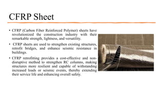
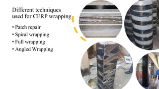
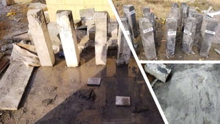
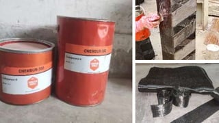
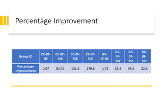
Performance of Environmental
friendly Geopolymer concrete
structural members
• Muhammad Ahsan Sami 19-CE-45
• Ahmad Rasheed 19-CE-57
• Zawar Ahmad 19-CE-81
• Muhammad Ihtisham Farid 19-CE-93
Geopolymer
Concrete
• Geopolymer concrete an eco-friendly and
innovative construction material.
• An alternative to traditional Portland
cement-based concrete.
• Produced by combining aluminosilicate
materials like fly ash or metakaolin with an
alkaline activator solution.
• Geopolymer concrete act as a binder,
binding the aggregate particles to create a
durable material.
• Introduced in 1970s.
• Several structures have been constructed
such as The University of Queensland’s
Global Change Institute (GCI).
The University of Queensland’s Global Change Institute (GCI).
Benefits of
Geopolymer
Concrete
• Environmental Sustainability
• Lower Carbon Footprint
• High Compressive Strength
• Chemical Resistance
• Fire Resistance
• Reduce permeability
• Faster hardening and setting
• Long term durability
• Economic Benefits
Why prefer GPC over Conventional concrete?
Reduction in production of Carbon foot
prints.
The production of 1 ton of cement
emits around 0.9 tons of CO2 globally.
Less water consumption in
construction activities while using GPC.
Requires no curing
Utilization of industrial waste fly ash,
slag, quarry rock dust etc.
Elements of
Geopolymer Concrete
•Slag
•Fly ash
•Sodium silicate
•Sodium hydroxide
What is Retrofitting?
• Retrofitting of structures
refers to the process of
strengthening or upgrading
existing buildings, bridges,
or other infrastructure to
improve their performance,
safety, and durability.
Purpose of Retrofitting
• Upgrade existing structures
• To meet modern safety, functionality, and
environmental standards.
• Strengthening buildings against seismic forces,
improving energy efficiency and adapting structures for
new uses.
• Retrofitting extends the life of buildings, enhances
safety, and reduces environmental impact.
• For historical preservation and cost-effective solutions,
making it a vital practice for improving infrastructure
resilience and sustainability.
Techniques for
Retrofitting/Strengthening
• Steel Jacketing
• Concrete Jacketing
• FRP Bars
• GFRP
• CFRP
Steel Jacketing
• Retrofitting technique used to strengthen and
reinforce concrete structures.
• It involves surrounding the existing structural
element with a layer of steel, usually in the
form of plates or sections, to enhance its load-
carrying capacity, and provide better resistance
to seismic forces and other external stresses.
• Corrosion of the steel plates is the major
drawback of this technique.
• Frequent maintenance is required to keep it
safe.
Concrete Jacketing
• It includes an addition of new layer of high
strength concrete around the existing structure to
improve its load-carrying capacity, enhance
durability, and increase resistance to various
stresses.
• There is a significant increase in the self weight of
the structural members.
• It can be a time-consuming process, especially
when considering the need for formwork
installation, curing time, and potential disruption to
the building occupants.
FRP Bars
• FRP bars are made of high-strength fibers, such as
carbon, glass, or aramid, embedded in a polymer
matrix, typically epoxy.
• FRP bars are applied to the surface or embedded
within the concrete to enhance its load-carrying
capacity, improve structural performance.
• FRP bars may have lower fire resistance compared
to traditional steel reinforcement, requiring
additional fire protection measures in certain
applications.
GFRP Sheet
CFRP Sheet
• CFRP (Carbon Fiber Reinforced Polymer) sheets have
revolutionized the construction industry with their
remarkable strength, lightness, and versatility.
• CFRP sheets are used to strengthen existing structures,
retrofit bridges, and enhance seismic resistance in
buildings.
• CFRP retrofitting provides a cost-effective and non-
disruptive method to strengthen RC columns, making
structures more resilient and capable of withstanding
increased loads or seismic events, thereby extending
their service life and enhancing overall safety.
Different techniques
used for CFRP wrapping
• Patch repair
• Spiral wrapping
• Full wrapping
• Angled Wrapping
Preparation
of
Specimen
• First of all, the GPC surface was cleaned and
made ready by removing loose or damaged
material, dust, filth, or other pollutants by
hammering them out of the specimens.
• Filling of cracks with GPC mortar (50% FA +
50% Slag) using NaOH and Na2SiO3 as alkali
activators.
• After grinding, the holes were filled with
epoxy to create an equal surface and prevent
air pockets.
• Chemdur-300 (components A and B) were
combined and applied in a 2:1 ratio to the GPC
surface as a bonding agent to create a strong
connection between the concrete and the CFRP.
Mix Proportions
Mix Proportions (%) Mix Quantities (Kg/m3)
Sr.
No.
Group
ID
Specimen
ID
OPC
FA
SG
Sand
CA
OPC
FA
SG
NaOH
Na2SiO3
SP
Water
1 CC CC-0F-0E 100   640 1201 370   53 107 4 170
CC-0F-15E 100   643 1206 370   53 107 4 170
CC-0F-35E 100   640 1201 370   53 107 4 170
CC-0F-50E 100   643 1206 370   53 107 4 170
2 GC GC-0F-0E  50 50 643 1206  200 200 53 107 8 
GC-0F-15E  50 50 643 1206  200 200 53 107 8 
GC-0F-35E  50 50 646 1212  200 200 53 107 8 
GC-0F-50E  50 50 643 1206  200 200 53 107 8
CFRP wrapping pattern
• The CFRP strips are positioned at an
angle of 20 degrees relative to horizontal
axis.
• It helps distribute the applied load more
effectively and enhances the columns'
resistance to axial and lateral forces.
• The CFRP strips are carefully placed on
the columns' surface, ensuring that they
adhere well to the binding material.
• The strips are applied with appropriate
tension and pressure to ensure intimate
contact and eliminate any air bubbles or
wrinkles.
Testing of columns
• A 20 mm magnetic LVDT device was used to test
the columns under 5000KN CTM and at a deflection
rate of 1mm/minute.
• The load was applied in regular 1 KN/s intervals.
• A strong circular steel pin connected to a bearing
plate was positioned for the eccentric and concentric
loading.
• The specimens were tested under unidirectional axial
loading till complete failure.
Cont..
• Column were wrapped in 76 mm wide by 3.2 mm
thick steel collars prior to testing.
• To assure an even load distribution, a layer of
plaster of Paris with minimum thickness was put to
the upper and lower faces of the column.
Failure Pattern
• The failure pattern was observed at the top and center of
diamond pattern at the column.
• The technique was effective at the edges of the columns.
Results and
discussion
The maximum load beared by group CC specimens
shows an improvement in strength of 0.67%, 92.75%,
131.32%, 279.8% respectively.
The maximum load beared by group GC specimens
shows improvement in strength of -1.75%, 35.4%,
95.4%, 22.6% respectively.
The strength of GC group increases at 15E,35E and 50E
but decreases at 0E. However, there is an increase in
load carrying capacity as compare to results before
strenghtening.
Geopolymer Concrete groups showed lower ultimate
load values than their CC group.
Graphical representation
Percentage Improvement
Group ID
CC-0F-
0E
CC-0F-
15E
CC-0F-
35E
CC-0F-
50E
GC-
0F-0E
GC-
0F-
15E
GC-
0F-
35E
GC-
0F-
50E
Percentage
Improvement
0.67 92.75 131.3 279.8 -1.75 35.4 95.4 22.6
Conclusions
 From the results it has been demonstrated that the improvement in strength of conventional
concrete (CC) and Geopolymer Concrete (GC) columns increases at 0E, 15E, 35E and 50E. But
in the case of GC as the eccentricity increases the improvement in strength increases but at 50E
decreases in strength improvement corresponding to their 15E and 35E columns by wrapping the
CFRP with 82mm wide strips at 20o from the horizontal.
 In the case of conventional concrete columns, the load values were increased as eccentricity was
increased from 0 to 15 and decreased to 35 but again increased at 50 mm.
 In case of Geopolymer concrete columns it shows inverse relationship, as eccentricity value
increases the ultimate load carrying capacity of the columns decreases from 0 to 15, 35 and 50E.
Cont..
 By comparing the CC columns with the GC columns after strengthening, CC columns shows
more strength than GC columns.
Recommendations
 To increase strength and withstand bending and shear stresses the wrapping pattern and
orientation of CFRP layers should be carefully planned based on the structural analysis.
 By applying the CFRP cut strips at 20o angle we ensure more overlapping at edges and
consequently there is an increase in strength of columns.
 The manufacturer's guidelines should be followed when selecting the bonding agent, and the
manufacturer's recommendations should be followed while applying it.
FYP Presentation group 1.pptx

FYP Presentation group 1.pptx

  • 2.
    Performance of Environmental friendlyGeopolymer concrete structural members • Muhammad Ahsan Sami 19-CE-45 • Ahmad Rasheed 19-CE-57 • Zawar Ahmad 19-CE-81 • Muhammad Ihtisham Farid 19-CE-93
  • 3.
    Geopolymer Concrete • Geopolymer concretean eco-friendly and innovative construction material. • An alternative to traditional Portland cement-based concrete. • Produced by combining aluminosilicate materials like fly ash or metakaolin with an alkaline activator solution. • Geopolymer concrete act as a binder, binding the aggregate particles to create a durable material. • Introduced in 1970s. • Several structures have been constructed such as The University of Queensland’s Global Change Institute (GCI).
  • 4.
    The University ofQueensland’s Global Change Institute (GCI).
  • 5.
    Benefits of Geopolymer Concrete • EnvironmentalSustainability • Lower Carbon Footprint • High Compressive Strength • Chemical Resistance • Fire Resistance • Reduce permeability • Faster hardening and setting • Long term durability • Economic Benefits
  • 6.
    Why prefer GPCover Conventional concrete? Reduction in production of Carbon foot prints. The production of 1 ton of cement emits around 0.9 tons of CO2 globally. Less water consumption in construction activities while using GPC. Requires no curing Utilization of industrial waste fly ash, slag, quarry rock dust etc.
  • 7.
    Elements of Geopolymer Concrete •Slag •Flyash •Sodium silicate •Sodium hydroxide
  • 8.
    What is Retrofitting? •Retrofitting of structures refers to the process of strengthening or upgrading existing buildings, bridges, or other infrastructure to improve their performance, safety, and durability.
  • 9.
    Purpose of Retrofitting •Upgrade existing structures • To meet modern safety, functionality, and environmental standards. • Strengthening buildings against seismic forces, improving energy efficiency and adapting structures for new uses. • Retrofitting extends the life of buildings, enhances safety, and reduces environmental impact. • For historical preservation and cost-effective solutions, making it a vital practice for improving infrastructure resilience and sustainability.
  • 10.
    Techniques for Retrofitting/Strengthening • SteelJacketing • Concrete Jacketing • FRP Bars • GFRP • CFRP
  • 11.
    Steel Jacketing • Retrofittingtechnique used to strengthen and reinforce concrete structures. • It involves surrounding the existing structural element with a layer of steel, usually in the form of plates or sections, to enhance its load- carrying capacity, and provide better resistance to seismic forces and other external stresses. • Corrosion of the steel plates is the major drawback of this technique. • Frequent maintenance is required to keep it safe.
  • 12.
    Concrete Jacketing • Itincludes an addition of new layer of high strength concrete around the existing structure to improve its load-carrying capacity, enhance durability, and increase resistance to various stresses. • There is a significant increase in the self weight of the structural members. • It can be a time-consuming process, especially when considering the need for formwork installation, curing time, and potential disruption to the building occupants.
  • 13.
    FRP Bars • FRPbars are made of high-strength fibers, such as carbon, glass, or aramid, embedded in a polymer matrix, typically epoxy. • FRP bars are applied to the surface or embedded within the concrete to enhance its load-carrying capacity, improve structural performance. • FRP bars may have lower fire resistance compared to traditional steel reinforcement, requiring additional fire protection measures in certain applications.
  • 14.
  • 15.
    CFRP Sheet • CFRP(Carbon Fiber Reinforced Polymer) sheets have revolutionized the construction industry with their remarkable strength, lightness, and versatility. • CFRP sheets are used to strengthen existing structures, retrofit bridges, and enhance seismic resistance in buildings. • CFRP retrofitting provides a cost-effective and non- disruptive method to strengthen RC columns, making structures more resilient and capable of withstanding increased loads or seismic events, thereby extending their service life and enhancing overall safety.
  • 16.
    Different techniques used forCFRP wrapping • Patch repair • Spiral wrapping • Full wrapping • Angled Wrapping
  • 17.
    Preparation of Specimen • First ofall, the GPC surface was cleaned and made ready by removing loose or damaged material, dust, filth, or other pollutants by hammering them out of the specimens. • Filling of cracks with GPC mortar (50% FA + 50% Slag) using NaOH and Na2SiO3 as alkali activators. • After grinding, the holes were filled with epoxy to create an equal surface and prevent air pockets. • Chemdur-300 (components A and B) were combined and applied in a 2:1 ratio to the GPC surface as a bonding agent to create a strong connection between the concrete and the CFRP.
  • 20.
    Mix Proportions Mix Proportions(%) Mix Quantities (Kg/m3) Sr. No. Group ID Specimen ID OPC FA SG Sand CA OPC FA SG NaOH Na2SiO3 SP Water 1 CC CC-0F-0E 100 640 1201 370 53 107 4 170 CC-0F-15E 100 643 1206 370 53 107 4 170 CC-0F-35E 100 640 1201 370 53 107 4 170 CC-0F-50E 100 643 1206 370 53 107 4 170 2 GC GC-0F-0E 50 50 643 1206 200 200 53 107 8 GC-0F-15E 50 50 643 1206 200 200 53 107 8 GC-0F-35E 50 50 646 1212 200 200 53 107 8 GC-0F-50E 50 50 643 1206 200 200 53 107 8
  • 21.
    CFRP wrapping pattern •The CFRP strips are positioned at an angle of 20 degrees relative to horizontal axis. • It helps distribute the applied load more effectively and enhances the columns' resistance to axial and lateral forces. • The CFRP strips are carefully placed on the columns' surface, ensuring that they adhere well to the binding material. • The strips are applied with appropriate tension and pressure to ensure intimate contact and eliminate any air bubbles or wrinkles.
  • 22.
    Testing of columns •A 20 mm magnetic LVDT device was used to test the columns under 5000KN CTM and at a deflection rate of 1mm/minute. • The load was applied in regular 1 KN/s intervals. • A strong circular steel pin connected to a bearing plate was positioned for the eccentric and concentric loading. • The specimens were tested under unidirectional axial loading till complete failure.
  • 23.
    Cont.. • Column werewrapped in 76 mm wide by 3.2 mm thick steel collars prior to testing. • To assure an even load distribution, a layer of plaster of Paris with minimum thickness was put to the upper and lower faces of the column.
  • 24.
    Failure Pattern • Thefailure pattern was observed at the top and center of diamond pattern at the column. • The technique was effective at the edges of the columns.
  • 25.
    Results and discussion The maximumload beared by group CC specimens shows an improvement in strength of 0.67%, 92.75%, 131.32%, 279.8% respectively. The maximum load beared by group GC specimens shows improvement in strength of -1.75%, 35.4%, 95.4%, 22.6% respectively. The strength of GC group increases at 15E,35E and 50E but decreases at 0E. However, there is an increase in load carrying capacity as compare to results before strenghtening. Geopolymer Concrete groups showed lower ultimate load values than their CC group.
  • 26.
  • 27.
  • 28.
    Conclusions  From theresults it has been demonstrated that the improvement in strength of conventional concrete (CC) and Geopolymer Concrete (GC) columns increases at 0E, 15E, 35E and 50E. But in the case of GC as the eccentricity increases the improvement in strength increases but at 50E decreases in strength improvement corresponding to their 15E and 35E columns by wrapping the CFRP with 82mm wide strips at 20o from the horizontal.  In the case of conventional concrete columns, the load values were increased as eccentricity was increased from 0 to 15 and decreased to 35 but again increased at 50 mm.  In case of Geopolymer concrete columns it shows inverse relationship, as eccentricity value increases the ultimate load carrying capacity of the columns decreases from 0 to 15, 35 and 50E.
  • 29.
    Cont..  By comparingthe CC columns with the GC columns after strengthening, CC columns shows more strength than GC columns.
  • 30.
    Recommendations  To increasestrength and withstand bending and shear stresses the wrapping pattern and orientation of CFRP layers should be carefully planned based on the structural analysis.  By applying the CFRP cut strips at 20o angle we ensure more overlapping at edges and consequently there is an increase in strength of columns.  The manufacturer's guidelines should be followed when selecting the bonding agent, and the manufacturer's recommendations should be followed while applying it.