Downloaded 236 times


![Dept. Of Civil Engineering,CIEM 30 |
P a g e
REFERENCE
BubbleDeck.com
Martina Schnellenbach-Held,StefanEhmann,KarstenPfeffer:“BubbleDeck - New
Ways inConcrete Building”.Technische UniversitätDarmstadt,DACON Volume 13,
1998
Martina Schnellenbach-Held,KarstenPfeffer:“BubbleDeckDesignof BiaxialHollow
Slabs”.Technische UniversitätDarmstadt,DACON Volume 14,1999
BubbleDeckReportfromA+U ResearchInstitute /ProfessorKleinmann - the
EindhovenUniversityof Technology/the Netherlands,1999
BubbleDeckTestReportbyKoning&Bienfaitb.v./The Netherlands,1998
Reportof BubbleDeckfromTechnischeUniversitaetinCottbus
Reportfrom the EindhovenUniversityof Technology/the Netherlands:”Broad
comparisonof concrete floorsystems”.December1997
BubbleDeckReportfromTechnical Universityof Denmark,2003
Reportfrom AdviesbureauPeutz&Associesb.v.:”Comparisonof BubbleDeckvs.
Hollowcore”.Netherlands,1997
"Optimisingof Concrete Constructions"; - The EngineeringSchool inHorsens/
Denmark,2000
BubbleDeck.nl:CUR-aanbeveling86-01
Martina Schnellenbach-Held,HeikoDenk:“BubbleDeckTime-DependentBehaviour,
Local PunchingAdditional Experimental Tests”.Technische UniversitätDarmstadt,
DACON Volume 14,1999
Schnellenbach-Held,M.,Pfeffer,K.:“Tragverhaltenzweiachsiger
Hohlkörperdecken,Beton- undStahlbetonbau”96 [9],573-578 (2001)
Pfeffer,K.:“UntersuchungzumBiege-undDurchstanztragverhaltenvon
zweiachsigenHohlkörperdecken”.Fortschritt-Berichte VDI,VDI-Verlag,Düsseldorf
2002
"PunchingShearStrengthof BubbleDeck" - The Technical Universityof Denmark,
2002
BubbleDeckTestreportfromUniversityof DarmstadtbyMarkus Aldejohann,
Martina Schnellenbach-Held,2003
BubbleDeckReportfromAECConsultingEngineersLtd./ProfessorM.P.Nielsen -
The Technical Universityof Denmark,1993
BubbleDeck TestreportfromUniversityof DarmstadtbyMarkus Aldejohannand
Martina Schnellenbach-Held,2002
TNO-ReportonBubbleDeckforthe WeenaTower/Rotterdam/ the Netherlands,
1997
TNO-Reportfor230 mm BubbleDeck:”Fire-safe in120 minutes”the Netherlands,
1999
German TestCertificate NumberP-SAC02/IV-065accordingto DIN 4102-2
concerningBubbleDeck® slabs,2001](https://image.slidesharecdn.com/reportsheetonu-bootbeton-180420111216/75/Report-sheet-on-u-boot-beton-30-2048.jpg)

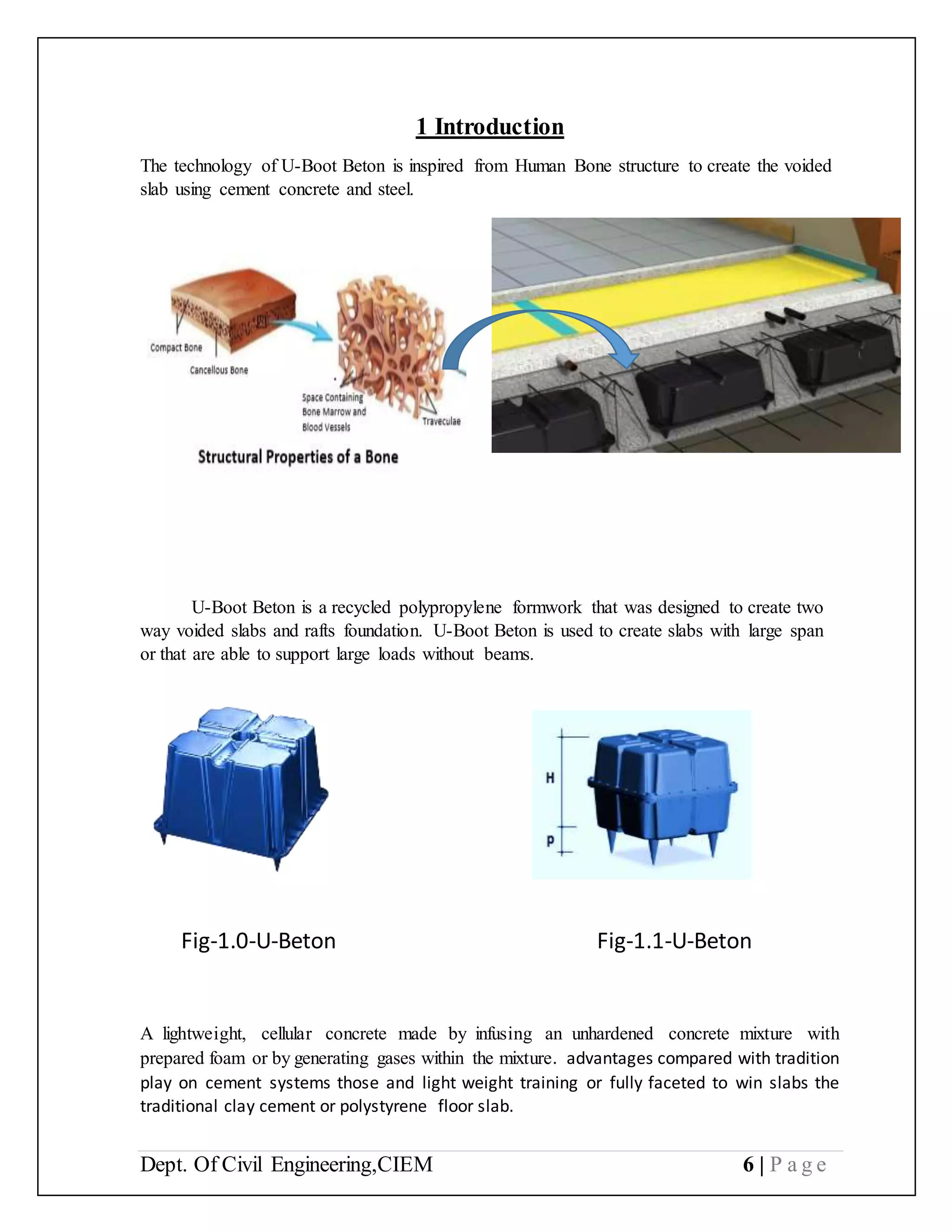
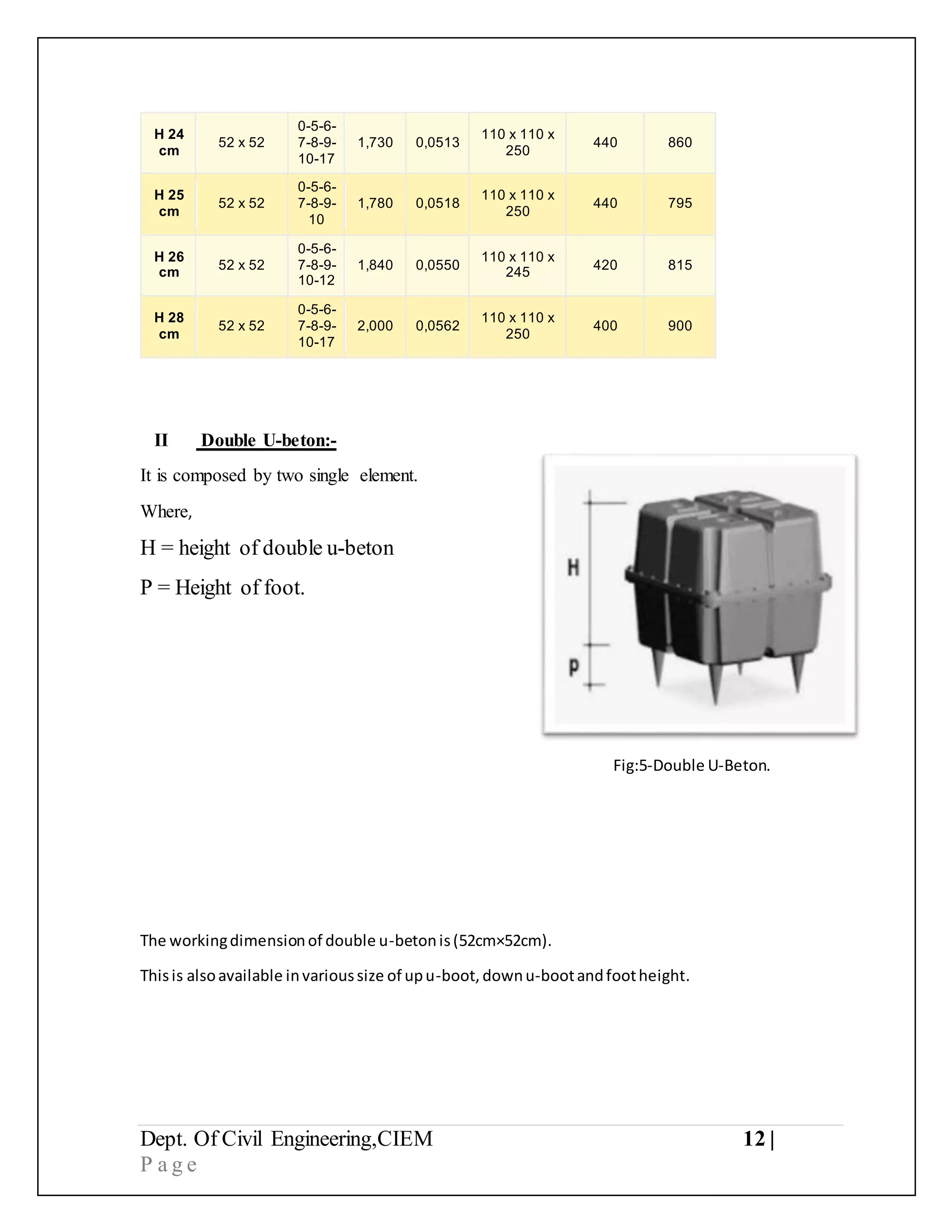
The document discusses U-Boot Beton technology, which is a recycled polypropylene formwork used to create two-way voided slabs and raft foundations. U-Boot Beton consists of interconnected U-shaped elements that are installed to form voids in concrete slabs, providing strength and reduced weight. The document describes the parts of U-Boot Beton including spacers, connection bridges, and closing plates used during installation. It also discusses single and double U-Boot Beton elements and provides tables of specifications for different sizes.


![u boot.pptxluytdrstdyui9op-]oioutyrerstrdtyuoio0pi987itryetesdrfthgyhk](https://cdn.slidesharecdn.com/ss_thumbnails/ravichandrauboot-250129232012-0f0baaa1-thumbnail.jpg?width=640&height=640&fit=bounds)


