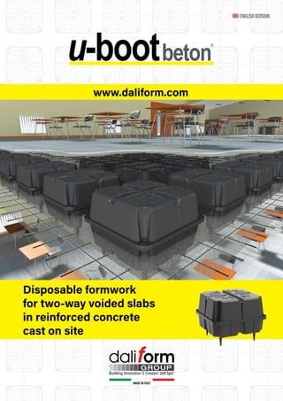
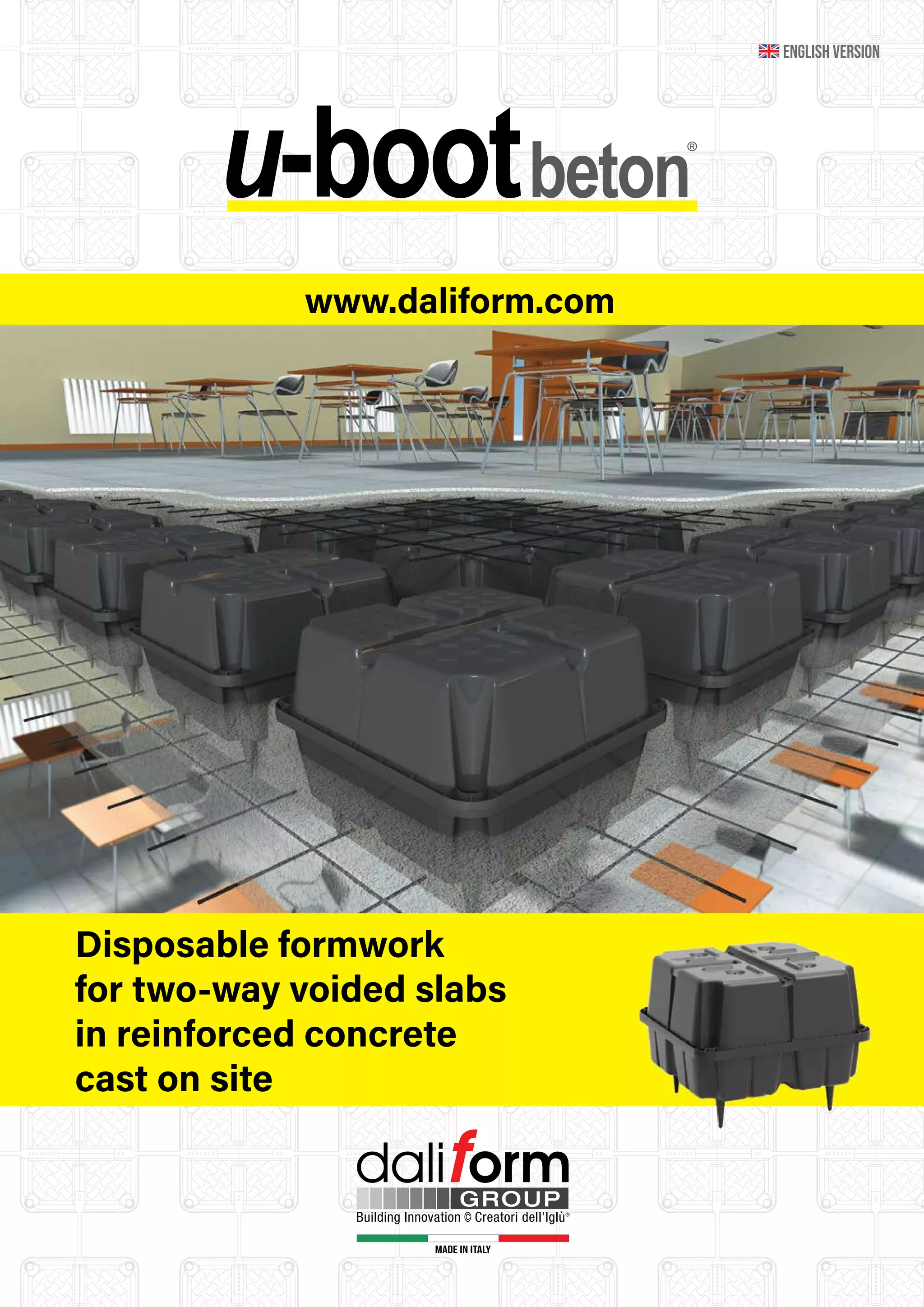
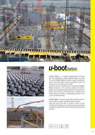
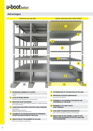
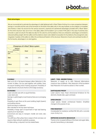
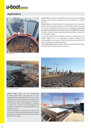
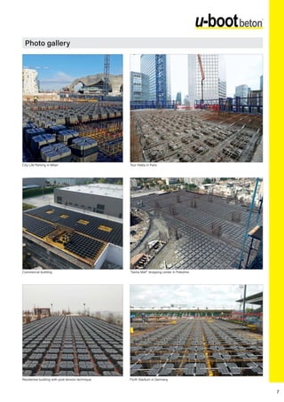
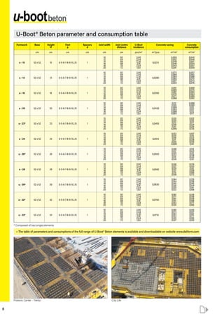
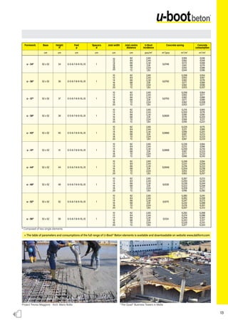
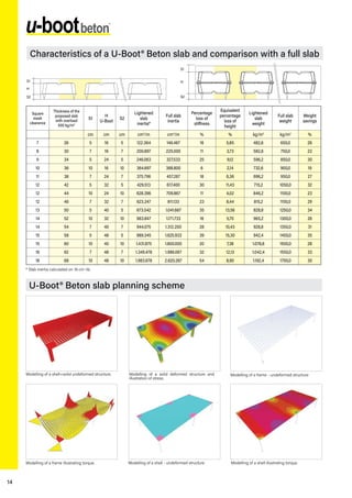
www.daliform.com
MADE IN ITALY
Disposable formwork
for two-way voided slabs
in reinforced concrete
cast on site
ENGLISH VERSION
Formwork
Utility passage
Foundations
Certifications
KEY:
SWITCHBOARD
Telephone +39 0422 2083
TECHNICAL SECRETARY OFFICE
tecnico@daliform.com
FOREIGN COMMERCIAL SECRETARY OFFICE
export@daliform.com
3
U-Boot® Beton is a recycled polypropylene formwork
that was designed to create lightened slabs and rafts.
The use of U-Boot® Beton formwork makes it possible to
create mushroom pillars, with the possibility to have the
mushroom in the thickness of the slab.
Thanks to the conic elevator foot, immerging the U-Boot®
Beton formworks in the concrete casting will create a
gridwork of mutually perpendicular beams closed from the
bottom and the top by a flat plate that is created with a
single casting; this results in considerable reduction in the
use of concrete and steel.
U-Boot® Beton is used to create slabs with large span or
that are able to support large loads without beams.
Light and quick and easy to position, thanks to their
modularity the designer can vary the geometric parameters
as needed to adapt to all situations with great architectural
freedom.
4
1
6
5
2
7
3
8
9
10
12
11
4
1
3
2
2
3
4
6
12
11
6
7
4
12
11
8
9
10
5
Advantages
System optimised with U-Boot® Beton
Traditional one way slab
REDUCTION IN THE NUMBER OF PILLARS
OPTIMISATION OF THE SECTION OF PILLARS
IMPROVED ACOUSTIC BEHAVIOUR
POSSIBILITY OF PASSING UTILITIES IN THE
THICKNESS OF THE SLAB
POSSIBILITY TO USE IT WITH
POST-TENSION
REDUCTION IN THE OVERALL LOAD OF THE
STRUCTURE WEIGHING ON THE PILLARS AND
THE FOUNDATION
FLEXIBILITY IN THE REALIZATION OF OPENINGS
AFTER THE EXECUTION OF THE SLAB
LESS DEEP FOUNDATION EXCAVATION
INCREASED NUMBER OF FLOORS
LACK OF RISING BEAMS
REDUCED SLAB THICKNESS
LARGE SPAN AND GREAT ARCHITECTURAL FREEDOM
Possibility to gain floors at the same building height (towers) and building
volume.
Flat soffit for greater flexibility when installing systems.
Thinner slabs but with equal loads and clearances, or bigger clearances
with an equal thickness.
Larger spaces.
Greater architectural freedom.
Simplified changes to the purpose of use.
Wider bays. Facilitated use reallocation.
Lower costs for foundation excavations. Less excavation.
Less acoustic transmittance.
5
FLEXIBLE
Span up to 20 m. No beams between pillars. Reduction in the
number of pillars. Can be used together with prefabs. Does
not require handling and/or hoisting equipment. Possibility of
single direction structures thanks to the bridge accessory.
ECONOMIC
Lower concrete cost with an equal thickness.
Lower steel cost.
Savings in useful height on each level as there are no emerging
beams.
Possibility to gain floors at the same building height (towers)
and building volume.
Quick and easy to implement.
Also indicated for the top-down technique.
Possibility of large span at equal load or high load bearing
capacity at an equal span.
Economical and easy to transport, handle and store, also
outdoors.
The soffit has a flat surface that is ready to finish and does not
require a false ceiling for aesthetic purposes.
If a false ceiling, is required it can be created faster.
LIGHT - THIN - BIDIRECTIONAL
Reduction of weight up to 40%. Reduced deformations
(maximum loss of stiffness- 15%). Reduction of the foundation
load. Reduction of of columns section or their number.
EARTHQUAKE PROOF
Lower seismic mass. Fewer dimensional limitations for the
elements. Double slab, upper and lower.
OPEN SPACES
Larger spaces. Greater architectural freedom. Simplified
changes to the purpose of use.
FIRE RESISTANT
Considerable fire resistance certified REI 180 with a concrete
cover of only 3 cm.
IMPROVED ACOUSTIC BEHAVIOUR
Thanks to the increased stiffness of the lower and upper slabs,
acoustic transmittancy is decreased.
Real advantages
We are incorrectly led to estimate the advantage of a slab lightened with U-Boot® Beton limiting it to a mere comparison between
savings in concrete and the cost of the formwork on the level of the slabs only. In this way however, as the analysis is immediate
and intuitive, it does not account for the various economic, practical and operational advantages provided with U-Boot® Beton
for the entire structure: less use of iron in the slabs, pillars and foundation up to a total of 15% (also in the case of variants); less
concrete is used not only for the slabs but also for the columns and foundations; there are antiseismic advantages connected to
reduced building weight; slimmer pillars and foundations, lower costs related to excavation for foundations; the arrangement, also
irregularly if needed, of the pillars to reflect the architectural freedom of the structure. Reduction of work and overhead transfer of
the formworks; advantages in on-site logistics.
Cheapness of U-Boot® Beton system
Steel Concrete
Slab -15% -25%
Pillars -20% -3/5%
Foundations -20% -3/5%
Structure
type
Material
consumption
6
Applications
U-Boot® Beton is used in all applications that require a structural plate
together with the need to use less concrete and therefore for a lighter
structure.
U-Boot® Beton is the ideal solution for creating slabs with a large span
and/or great load-bearing capacity: it is particularly suited for structures
that require considerable open spaces, such as executive, commercial
and industrial buildings as well as public, civil and residential structures.
It makes it possible to more irregularly distribute the pillars, as beams do
not need to be created.
In the case of yards that are difficult to access or restructuring work,
U-Boot® Beton, due to its stackability, modularity, lightness and
manoeuvrability, can be used to make horizontal structures without the
help of handling and hoisting equipment.
With U-Boot® Beton also foundation rafters can be created with a larger
thickness with a reduced amount of concrete.
U-Boot® Beton allows even the reinforcement
of existing slabs through the execution of a self-
supporting voided slab without the use of the feet
superimposed on the existing floor and casted on the
extrados of the latter, which will act as a formwork.
In this way you will have the possibility to reduce to
a minimum the increase of the self-weight and the
consequent increase of the loads transmitted to the
existing structures.
With this technique you will carry out work for the
construction of the new slab without having to interrupt
the activities in the lower floors, thanks to the extreme
lightness of the system.
Tour Alto in Paris
Vimar’s industrial building “Mall of Sousse” shopping center in Tunisia
7
Photo gallery
City Life Parking in Milan
“Sama Mall” shopping center in Palestine
Tour Hekla in Paris
Residential building with post-tension technique Fürth Stadium in Germany
Commercial building
52 x 52
13
0-5-6-7-8-9-10
1
1,406
0,0280
110x110x212
600
857
52 x 52
16
0-5-6-7-8-9-10
1
2,044
0,0350
110x110x254
440
912
52 x 52
18
0-5-6-7-8-9-10-12
1
1,784
0,0396
110x110x249
440
798
52 x 52
20
0-5-6-7-8-9-10
1
1,644
0,0430
110x110x236
460
769
52 x 52
22
0-5-6-7-8-9-10-12
1
1,882
0,0470
110x110x253
440
841
52 x 52
20
0-5-6-7-8-9-10-15
1
0,0426
110x110x250
10
10
52 x 52
10
0-5-6-7-8-9-10
1
1,395
0,0213
110x110x247
720
1.017
52 x 52
28
0-5-6-7-8-9-10-17
1
2,152
0,0562
110x110x236
400
874
52 x 52
28
0-5-6-7-8-9-10-15
1
0,0609
110x110x250
18
10
52 x 52
29
0-5-6-7-8-9-10-15
1
0,0630
110x110x250
16
13
52 x52
30
0-5-6-7-8-9-10-15
1
0,0643
110x110x250
20
10
52 x52
31
0-5-6-7-8-9-10-15
1
0,0676
110x110x250
18
13
28 28 29 30 31
24 25 26 26
23
20 22
20
16 18
13
10
9 17
52 x 52
24
0-5-6-7-8-9-10-12
1
2,033
0,0513
110x110x254
440/420**
908/784**
52 x 52
25
0-5-6-7-8-9-10
1
1,849
0,0518
110x110x249
440
827
52 x 52
26
0-5-6-7-8-9-10-12
1
2,044
0,0550
110x110x249
420
871
52 x 52
26
0-5-6-7-8-9-10-15
1
0,0563*
110x110x250
52 x 52
23
0-5-6-7-8-9-10-15
1
0,0493
110x110x250
13
10
d
H
p
H
d
p
d
52
52
13 - 16
13 - 10
single single single
single single double double double
single single single single single double double double double
SINGLE
DOUBLE
H cm
52 x 52
13
0-5-6-7-8-9...15
1
1,730
0,0290
110x110x248
460
809
52 x 52
14
0-5-6-7-8-9...15
1
1,650
0,0310
110x110x249
460
846
52 x 52
16
0-5-6-7-8-9...15
1
1,784
0,0350
110x110x250
460
834
52 x 52
18
0-5-6-7-8-9...15
1
1,860
0,0387
110x110x254
460
869
52 x 52
20
0-5-6-7-8-9...15
1
1,806
0,0427
110x110x249
440
808
52 x 52
22
0-5-6-7-8-9...15
1
1,947
0,0465
110x110x249
440
870
52 x 52
20
0-5-6-7-8-9...20
1
0,0440
110x110x250
10
10
52 x 52
10
0-5-6-7-8-9...15
1
1,579
0,0220
110x110x243
460
739
52 x 52
28
0-5-6-7-8-9...15
1
2,271
0,0576
110x110x248
420
967
52 x 52
28
0-5-6-7-8-9...20
1
0,0608
110x110x250
18
10
52 x 52
29
0-5-6-7-8-9...20
1
0,0641
110x110x250
16
13
28 28 29
24 24 26 26 27
23
20 22
20
16 18
13 14
10
52 x 52
24
0-5-6-7-8-9...15
1
2,044
0,0503
110x110x250
440
912
52 x 52
24
0-5-6-7-8-9...20
1
0,0530
110x110x250
14
10
52 x 52
26
0-5-6-7-8-9...15
1
2,195
0,0540
110x110x247
420
935
52 x 52
26
0-5-6-7-8-9...20
1
0,0581*
110x110x250
52 x 52
27
0-5-6-7-8-9...20
1
0,0600
110x110x250
14
13
52 x 52
23
0-5-6-7-8-9...20
1
0,0510
110x110x250
13
10
d
H
p
H
d
p
d
52
52
13 - 16
13 - 10
single single single
single single single double double double double
single single double single single double double
SINGLE
DOUBLE
H cm
cm
cm
cm
cm
kg
m3
cm
pcs/PAL
kg/PAL
cm
cm
cm
cm
cm
cm
kg
m3
cm
pcs/PAL
kg/PAL
cm
cm
Working dimensions
Height H
Foot height p
Spacer height d
Weight per piece
Piece volume
Pallet dimensions
Pallet pieces
Pallet weight
Composed of U-Boot UP
Composed of U-Boot DOWN
Working dimensions
Height H
Foot height p
Spacer height d
Weight per piece
Piece volume
Pallet dimensions
Pallet pieces
Pallet weight
Composed of U-Boot UP
Composed of U-Boot DOWN
Range
* Volume related to one possible combination “UP + DOWN”
.
** U-Boot® Beton H 24 DOWN with feet ≥8 cm.
*Volume related to one possible combination “UP + DOWN”
.
Purpose:
creation of very rigid rafts, minimising the
quantity of concrete and the foundation
weight in the case of inconsistent ground
surfaces.
Advantages:
• lightens the structure
• less concrete use
• structure stiffness
• decrease on stress on the ground
• elimination of foundation piles
Among the various foundation types, rafts are one of the most well known.
They are used above all in ground conditions with little bearing capacity,
or with poor quality soil, large thicknesses must be used which increases
the construction cost.
Thanks to the use of U-Boot® Beton lightened rafts can be created with
the same performance but at a considerably lower cost.
Once drown in the concrete casting, U-Boot® Beton forms the structure
just like two full slabs, with a variable thickness, connected by a
perpendicular beam gridwork to form a bidirectional static honeycomb
plate.
For this concrete bed, the distribution of weights due to hight inertia is
rationalised in order to permit maximum stiffness and lightness for the
structure with a minimum amount of concrete, which makes it possible
to eliminate, where possible, the foundation piles.
Application examples: rafts
Application example: foundation raft with U-Boot® Beton double
20 52 20
48
10
10
FORMWORK
LOWER
REINFORCEMENT
NATURAL GROUND
LOWER
TRESTLEWORK
UPPER REINFORCEMENT
pillar
raft lightened with
U-Boot® Beton
foundation
piles
pillar
16
1
3
5
2
4
6
52 x 52
38
0-5-6-7-8-9-10-12-15
1
0,0826*
110x110x250
20-22-25-28
18-16-13-10
52 x 52
38
0-5-6-7-8-9...20
1
0,0815*
110x110x250
20-22-28
18-16-10
52 x 52
39
0-5-6-7-8-9-10-15
1
0,0830
110x110x250
26
13
52 x 52
39
0-5-6-7-8-9...20
1
0,0830
110x110x250
26
13
52 x 52
42
0-5-6-7-8-9-10-12
1
0,0909*
110x110x250
22 - 24 - 26
20 - 18 - 16
52 x 52
42
0-5-6-7-8-9...20
1
0,0892*
110x110x250
22 - 24 - 26
20 - 18 - 16
52 x 52
43
0-5-6-7-8-9-10-12
1
0,0914
110x110x250
25
18
52 x 52
43
0-5-6-7-8-9...20
1
0,0901
110x110x250
30
13
52 x 52
37
0-5-6-7-8-9-10-15
1
0,0793
110x110x250
24
13
52 x 52
37
0-5-6-7-8-9...20
1
0,0793
110x110x250
24
13
52 x 52
40
0-5-6-7-8-9-10-12
1
0,0866*
110x110x250
20 - 22 - 24
20 - 18 - 16
52 x 52
40
0-5-6-7-8-9...20
1
0,0854*
110x110x250
20-22-24-30
20-18-16-10
52 x 52
41
0-5-6-7-8-9-10-15
1
0,0868*
110x110x250
25 - 28
16 - 13
52 x 52
41
0-5-6-7-8-9...20
1
0,0866
110x110x250
28
13
52 x 52
44
0-5-6-7-8-9-10-12
1
0,0946*
110x110x250
22-24-26-28
22-20-18-16
52 x 52
44
0-5-6-7-8-9...20
1
0,0930*
110x110x250
22-24-26-28
22-20-18-16
52 x 52
45
0-5-6-7-8-9-10
1
0,0948
110x110x250
25
20
52 x 52
46
0-5-6-7-8-9-10-12
1
0,0983*
110x110x250
24 - 26 - 28
22 - 20 - 18
52 x 52
46
0-5-6-7-8-9...20
1
0,0968*
110x110x250
24-26-28-30
22-20-18-16
52 x 52
47
0-5-6-7-8-9-10-12
1
0,0988
110x110x250
25
22
52 x52
32
0-5-6-7-8-9-10-15
1
0,0700*
110x110x250
16 - 22
16 - 10
52 x52
32
0-5-6-7-8-9...20
1
0,0701*
110x110x250
16 - 22
16 - 10
52 x 52
48
0-5-6-7-8-9-10-12
1
0,1026*
110x110x250
24 - 26 - 28
24 - 22 - 20
52 x 52
48
0-5-6-7-8-9...20
1
0,1006*
110x110x250
24-26-28-30
24-22-20-18
52 x 52
49
0-5-6-7-8-9-10-12
1
0,1031
110x110x250
25
24
52 x 52
50
0-5-6-7-8-9-10-12
1
0,1063*
110x110x250
25 - 26 - 28
25 - 24 - 22
52 x 52
50
0-5-6-7-8-9...20
1
0,1043*
110x110x250
26 - 28 - 30
24 - 22 - 20
52 x 52
51
0-5-6-7-8-9-10
1
0,1068
110x110x250
26
25
52 x 52
33
0-5-6-7-8-9-10-15
1
0,0710
110x110x250
20
13
52 x 52
33
0-5-6-7-8-9...20
1
0,0718
110x110x250
20
13
52 x 52
52
0-5-6-7-8-9-10-12
1
0,1075
110x110x250
28
24
52 x 52
52
0-5-6-7-8-9...20
1
0,1080*
110x110x250
26 - 28 - 30
26 - 24 - 22
52 x 52
53
0-5-6-7-8-9-10
1
0,1080
110x110x250
28
25
52 x 52
54
0-5-6-7-8-9-10-12
1
0,1112
110x110x250
28
26
52 x 52
54
0-5-6-7-8-9...20
1
0,1116*
110x110x250
28 - 30
26 - 24
52 x 52
56
0-5-6-7-8-9-10-17
1
0,1124
110x110x250
28
28
52 x 52
56
0-5-6-7-8-9...20
1
0,1152*
110x110x250
28 - 30
28 - 26
52 x 52
58
0-5-6-7-8-9...20
1
0,1187
110x110x250
30
28
52 x 52
60
0-5-6-7-8-9...20
1
0,1222
110x110x250
30
30
52 x 52
36
0-5-6-7-8-9-10-12-15
1
0,0792*
110x110x250
18 - 20 - 26
18 - 16 - 10
52 x 52
36
0-5-6-7-8-9...20
1
0,0778*
110x110x250
18 - 20 - 26
18 - 16 - 10
52 x 52
34
0-5-6-7-8-9-10-15
1
0,0746*
110x110x250
24 - 18
10 - 16
52 x 52
34
0-5-6-7-8-9...20
1
0,0738*
110x110x250
24 - 18
10 - 16
52 x 52
35
0-5-6-7-8-9-10-15
1
0,0750*
110x110x250
22 - 25
13 - 10
52 x 52
35
0-5-6-7-8-9...20
1
0,0755
110x110x250
22
13
33
33
34
34
32
32
49 50
50
51
48
48
47
46
46
43
43
44
44
45
40
40
41
41
42
42
35
35
36
36
37
37
52
52
53 54
54
56
56 58 60
39
39
38
38
12
double
double
double
double
double
double
double
double
double
double
double
double
double
double
double
double
double
double
double
double
double
double
double
double
double
double
double double
double
double double
double
double double
double
double double
double
double double
double
double
double double double
52 x52
31
0-5-6-7-8-9...20
1
0,0678
110x110x250
18
13
31
double
52 x52
30
0-5-6-7-8-9...20
1
0,0647
110x110x250
20
10
30
double
52 x52
30
0-5-6-7-8-9...15
1
2,250
0,0611
110x110x251
420
958
30
single
Photographic details of the complete sequence of positioning the scaffolding, positioning the U-Boot® Beton, reinforconcrete of the structure to be performed on site, casting
and final smoothing.
The entire surface of the slab to be cast on site is shuttered
with wood deckings (or similar systems), then the lower
reinforconcrete bars are positioned in two mutually perpendicular
directions according to the design and the lattice for the upper
reinforconcrete is arranged.
The positioning of the reinforconcretes is completed by placing
above the U-Boot® Beton formwork the upper bars in the two
directions as well as the reinforcement for shear and punching
where necessary, according to the design.
Once suitably set, the casting can be restarted from the starting
point, completely burying the U-Boot® Beton. The casting is
then levelled and smoothed in a traditional manner.
The U-Boot® Beton formworks are positioned using the lateral
spacers joints to place them at the desired centre distance that
will determine the beam width. Thanks to the conic elevator
foot, theU-Boot® Beton formworks will be lifted from the surface,
making it possible for the lower slab to be formed. If double or
triple elements are used, these elements must first be assembled,
which will be supplied on distinct pallets in the yard.
The concrete casting must be performed in two phases to prevent
the floatation of the formworks: an initial layer will be cast to fill
a thickness equal to the height of the elevator foot. Casting will
continue for this first portion of the slab until the concrete starts to
set and become semi fluid.
Once the structure has hardened, the formwork can be removed.
The surface is smooth in correspondence of the soffit.
REINFORCEMENTS
SIDE
SHUTTERING
PROP
SPACER
PILLAR
FORMWORK
SIDE
SHUTTERING
PROP
SPACER
PILLAR
FORMWORK
BACKPROP
PILLAR
REINFORCEMENTS
SIDE
SHUTTERING
PROP
SPACER
TRADITIONAL SHUTTERING
IN WOOD OR METAL
LOWER REINFORCEMENT
PILLAR
UPPER REINFORCEMENT
REINFORCEMENTS
SIDE
SHUTTERING
PROP
SPACER
PILLAR
FORMWORK
SIDE
SHUTTERING
PROP
PILLAR
Wait a period of time (depending of fluidity of concret and
climatic condition) before the second casting of the concrete.
Comply with the requirements for concrete.
Installation
8
u - 10 52 x 52 10 0-5-6-7-8-9-10...15 1
10
12
14
16
18
20
62
64
66
68
70
72
2,60
2,44
2,30
2,16
2,04
1,93
0,0213
0,055
0,052
0,049
0,046
0,043
0,041
0,045
0,048
0,051
0,054
0,057
0,059
u - 13 52 x 52 13 0-5-6-7-8-9-10...15 1
10
12
14
16
18
20
62
64
66
68
70
72
2,60
2,44
2,30
2,16
2,04
1,93
0,0280
0,073
0,068
0,064
0,060
0,057
0,054
0,057
0,062
0,066
0,070
0,073
0,076
u - 16 52 x 52 16 0-5-6-7-8-9-10...15 1
10
12
14
16
18
20
62
64
66
68
70
72
2,60
2,44
2,30
2,16
2,04
1,93
0,0350
0,091
0,085
0,081
0,076
0,071
0,068
0,069
0,075
0,080
0,084
0,089
0,092
u - 20 52 x 52 20 0-5-6-7-8-9-10...15 1
10
12
14
16
18
20
62
64
66
68
70
72
2,60
2,44
2,30
2,16
2,04
1,93
0,0430
0,112
0,105
0,099
0,093
0,088
0,083
0,088
0,095
0,101
0,107
0,112
0,117
u - 23* 52 x 52 23 0-5-6-7-8-9-10...15 1
10
12
14
16
18
20
62
64
66
68
70
72
2,60
2,44
2,30
2,16
2,04
1,93
0,0493
0,128
0,120
0,113
0,106
0,101
0,095
0,102
0,110
0,117
0,124
0,129
0,135
u - 24 52 x 52 24 0-5-6-7-8-9-10...15 1
10
12
14
16
18
20
62
64
66
68
70
72
2,60
2,44
2,30
2,16
2,04
1,93
0,0513
0,133
0,125
0,118
0,111
0,105
0,099
0,107
0,115
0,122
0,129
0,135
0,141
u - 26* 52 x 52 26 0-5-6-7-8-9-10...15 1
10
12
14
16
18
20
62
64
66
68
70
72
2,60
2,44
2,30
2,16
2,04
1,93
0,0563
0,146
0,137
0,129
0,122
0,115
0,109
0,114
0,123
0,131
0,138
0,145
0,151
u - 28 52 x 52 28 0-5-6-7-8-9-10...15 1
10
12
14
16
18
20
62
64
66
68
70
72
2,60
2,44
2,30
2,16
2,04
1,93
0,0562
0,146
0,137
0,129
0,121
0,115
0,108
0,134
0,143
0,151
0,159
0,165
0,172
u - 29* 52 x 52 29 0-5-6-7-8-9-10...15 1
10
12
14
16
18
20
62
64
66
68
70
72
2,60
2,44
2,30
2,16
2,04
1,93
0,0630
0,164
0,154
0,145
0,136
0,129
0,122
0,126
0,136
0,145
0,154
0,161
0,168
u - 32* 52 x 52 32 0-5-6-7-8-9-10...15 1
10
12
14
16
18
20
62
64
66
68
70
72
2,60
2,44
2,30
2,16
2,04
1,93
0,0700
0,182
0,171
0,161
0,151
0,143
0,135
0,138
0,149
0,159
0,169
0,177
0,185
u - 33* 52 x 52 33 0-5-6-7-8-9-10...15 1
10
12
14
16
18
20
62
64
66
68
70
72
2,60
2,44
2,30
2,16
2,04
1,93
0,0710
0,185
0,173
0,163
0,153
0,145
0,137
0,145
0,157
0,167
0,177
0,185
0,193
Formwork Base Height
H
Feet
p
Spacers
d
Joist width Joist centre
distance
U-Boot
incidence
Concrete saving Concrete
consumption
cm cm cm cm cm cm pcs/m2
m3
/pcs m3
/m2
m3
/m2
U-Boot® Beton parameter and consumption table
City Life
* Composed of two single elements
» The table of parameters and consumptions of the full range of U-Boot® Beton elements is available and downloadable on website www.daliform.com
Protonic Center - Trento
13
u - 34* 52 x 52 34 0-5-6-7-8-9-10...15 1
10
12
14
16
18
20
62
64
66
68
70
72
2,60
2,44
2,30
2,16
2,04
1,93
0,0746
0,194
0,182
0,172
0,161
0,152
0,144
0,146
0,158
0,168
0,179
0,188
0,196
u - 36* 52 x 52 36 0-5-6-7-8-9-10...15 1
10
12
14
16
18
20
62
64
66
68
70
72
2,60
2,44
2,30
2,16
2,04
1,93
0,0792
0,206
0,193
0,182
0,171
0,162
0,153
0,154
0,167
0,178
0,189
0,198
0,207
u - 37* 52 x 52 37 0-5-6-7-8-9-10...15 1
10
12
14
16
18
20
62
64
66
68
70
72
2,60
2,44
2,30
2,16
2,04
1,93
0,0793
0,206
0,193
0,182
0,171
0,162
0,153
0,164
0,177
0,188
0,199
0,208
0,217
u - 38* 52 x 52 38 0-5-6-7-8-9-10...15 1
10
12
14
16
18
20
62
64
66
68
70
72
2,60
2,44
2,30
2,16
2,04
1,93
0,0826
0,215
0,202
0,190
0,178
0,169
0,159
0,165
0,178
0,190
0,202
0,211
0,221
u - 40* 52 x 52 40 0-5-6-7-8-9-10...15 1
10
12
14
16
18
20
62
64
66
68
70
72
2,60
2,44
2,30
2,16
2,04
1,93
0,0866
0,225
0,211
0,199
0,187
0,177
0,167
0,175
0,189
0,201
0,213
0,223
0,233
u - 41* 52 x 52 41 0-5-6-7-8-9-10...15 1
10
12
14
16
18
20
62
64
66
68
70
72
2,60
2,44
2,30
2,16
2,04
1,93
0,0868
0,226
0,212
0,200
0,187
0,177
0,168
0,184
0,198
0,210
0,223
0,233
0,242
u - 44* 52 x 52 44 0-5-6-7-8-9-10...15 1
10
12
14
16
18
20
62
64
66
68
70
72
2,60
2,44
2,30
2,16
2,04
1,93
0,0946
0,246
0,231
0,218
0,204
0,193
0,183
0,194
0,209
0,222
0,236
0,247
0,257
u - 48* 52 x 52 48 0-5-6-7-8-9-10...15 1
10
12
14
16
18
20
62
64
66
68
70
72
2,60
2,44
2,30
2,16
2,04
1,93
0,1026
0,267
0,250
0,236
0,222
0,209
0,198
0,213
0,230
0,244
0,258
0,271
0,282
u - 52* 52 x 52 52 0-5-6-7-8-9-10...15 1
10
12
14
16
18
20
62
64
66
68
70
72
2,60
2,44
2,30
2,16
2,04
1,93
0,1075
0,280
0,262
0,247
0,232
0,219
0,207
0,241
0,258
0,273
0,288
0,301
0,313
u - 56* 52 x 52 56 0-5-6-7-8-9-10...15 1
10
12
14
16
18
20
62
64
66
68
70
72
2,60
2,44
2,30
2,16
2,04
1,93
0,1124
0,292
0,274
0,259
0,243
0,229
0,217
0,268
0,286
0,301
0,317
0,331
0,343
Formwork Base Height
H
Feet
p
Spacers
d
Joist width Joist centre
distance
U-Boot
incidence
Concrete saving Concrete
consumption
cm cm cm cm cm cm pcs/m2
m3
/pcs m3
/m2
m3
/m2
Project Treviso Maggiore - Arch. Mario Botta “The Quad” Business Towers in Malta
* Composed of two single elements
» The table of parameters and consumptions of the full range of U-Boot® Beton elements is available and downloadable on website www.daliform.com
14
S1
S2
H
S1
S2
H
cm cm cm cm4
/cm cm4
/cm % % kg/m2
kg/m2
%
7 26 5 16 5 122.364 146.467 16 5,85 482,6 650,0 26
8 30 7 16 7 200.897 225.000 11 3,73 582,6 750,0 22
9 34 5 24 5 246.063 327.533 25 9,12 596,2 850,0 30
10 36 10 16 10 364.697 388.800 6 2,14 732,6 900,0 19
11 38 7 24 7 375.796 457.267 18 6,36 696,2 950,0 27
12 42 5 32 5 429.513 617.400 30 11,43 715,2 1050,0 32
12 44 10 24 10 628.396 709.867 11 4,02 846,2 1100,0 23
12 46 7 32 7 623.247 811.133 23 8,44 815,2 1150,0 29
13 50 5 40 5 673.542 1.041.667 35 13,56 828,8 1250,0 34
14 52 10 32 10 983.847 1.171.733 16 5,70 965,2 1300,0 26
14 54 7 40 7 944.075 1.312.200 28 10,43 928,8 1350,0 31
15 58 5 48 5 989.345 1.625.933 39 15,30 942,4 1450,0 35
15 60 10 40 10 1.431.875 1.800.000 20 7,38 1.078,8 1500,0 28
16 62 7 48 7 1.349.478 1.986.067 32 12,13 1.042,4 1550,0 33
18 68 10 48 10 1.983.678 2.620.267 54 8,90 1.192,4 1700,0 30
Modelling of a solid deformed structure and
illustration of stress.
Modelling of a shell+solid undeformed structure.
Modelling of a frame illustrating torque.
Modelling of a frame - undeformed structure
Modelling of a shell illustrating torque.
Modelling of a shell - undeformed structure
U-Boot® Beton slab planning scheme
Characteristics of a U-Boot® Beton slab and comparison with a full slab
* Slab inertia calculated on 16 cm rib.
Square
mesh
clearance
Thickness of the
proposed slab
with overload
500 kg/m2
S1
H
U-Boot
S2
Lightened
slab
inertia*
Full slab
inertia
Percentage
loss of
stiffness
Equivalent
percentage
loss of
height
Lightened
slab
weight
Full slab
weight
Weight
savings
cm cm cm cm4
/m cm4
/m % % kg/m2
kg/m2
%
15
Fig. 1
H
The U-Boot® Beton lightened plate slab has a perpendicular beam gridwork of the same
thickness as the slab that transfers all stresses directly to the pillars around which it will
suffice to leave a full zone of variable dimensions based on the shearing forces. Beam
dimensioning and their perfect implementation on site depends on the orderly and precise
layout of the lightening elements during installation but especially during casting.
Correct positioning of the U-Boot® Beton is guaranteed by an effective rigid spacer joint
with graduated scale with which the desired width of the beams is quickly determined. The
joint fits into the top of the formwork inside notches housing the fixing elements.
Thanks to this system, the connection of the formworks is simple and quick because it is not
hindered by the beam reinforcements.
The rigid interconnection ensures perfect geometric compliance with the design as well as
with the bearing capacity of the formworks when casting under the pressure of the concrete,
the weight of the operators and equipment.
Beams in the slab thickness - The spacer joint
Application example: voided slab with U-Boot® Beton single
Purpose:
creation of a large span slab with low deformation,
avoiding beams with non-standard thicknesses.
Advantages:
• lightens the structure
• less concrete use
• no lowered structures (beams)
• bidirectional structure
FORMWORK
25
L=VAR (SEE. PLAN)
2
cem.
cover.
3.5
cem.
cover.
34.5
40
+8.90m
10
24
6
40
GRECA Ø10/15 cm
In order to determine the thickness of the soffit slab, elevator feet of variable height, 11 to 20
cm, are available in addition to 0 to 10 cm feet: these accessories are to be grafted on site
on the existing ones.
Soffit slab with high thickness
16
1
3
5
2
4
6
Photographic details of the complete sequence of positioning the scaffolding, positioning the U-Boot® Beton, reinforconcrete of the structure to be performed on site, casting
and final smoothing.
The entire surface of the slab to be cast on site is shuttered
with wood deckings (or similar systems), then the lower
reinforconcrete bars are positioned in two mutually perpendicular
directions according to the design and the lattice for the upper
reinforconcrete is arranged.
The positioning of the reinforconcretes is completed by placing
above the U-Boot® Beton formwork the upper bars in the two
directions as well as the reinforcement for shear and punching
where necessary, according to the design.
Once suitably set, the casting can be restarted from the starting
point, completely burying the U-Boot® Beton. The casting is
then levelled and smoothed in a traditional manner.
The U-Boot® Beton formworks are positioned using the lateral
spacers joints to place them at the desired centre distance that
will determine the beam width. Thanks to the conic elevator
foot, theU-Boot® Beton formworks will be lifted from the surface,
making it possible for the lower slab to be formed. If double or
triple elements are used, these elements must first be assembled,
which will be supplied on distinct pallets in the yard.
The concrete casting must be performed in two phases to prevent
the floatation of the formworks: an initial layer will be cast to fill
a thickness equal to the height of the elevator foot. Casting will
continue for this first portion of the slab until the concrete starts to
set and become semi fluid.
Once the structure has hardened, the formwork can be removed.
The surface is smooth in correspondence of the soffit.
REINFORCEMENTS
SIDE
SHUTTERING
PROP
SPACER
PILLAR
FORMWORK
SIDE
SHUTTERING
PROP
SPACER
PILLAR
FORMWORK
BACKPROP
PILLAR
REINFORCEMENTS
SIDE
SHUTTERING
PROP
SPACER
TRADITIONAL SHUTTERING
IN WOOD OR METAL
LOWER REINFORCEMENT
PILLAR
UPPER REINFORCEMENT
REINFORCEMENTS
SIDE
SHUTTERING
PROP
SPACER
PILLAR
FORMWORK
SIDE
SHUTTERING
PROP
PILLAR
Wait a period of time (depending of fluidity of concret and
climatic condition) before the second casting of the concrete.
Comply with the requirements for concrete.
Installation
17
Purpose:
creation of very rigid rafts, minimising the
quantity of concrete and the foundation
weight in the case of inconsistent ground
surfaces.
Advantages:
• lightens the structure
• less concrete use
• structure stiffness
• decrease on stress on the ground
• elimination of foundation piles
Among the various foundation types, rafts are one of the most well known.
They are used above all in ground conditions with little bearing capacity,
or with poor quality soil, large thicknesses must be used which increases
the construction cost.
Thanks to the use of U-Boot® Beton lightened rafts can be created with
the same performance but at a considerably lower cost.
Once drown in the concrete casting, U-Boot® Beton forms the structure
just like two full slabs, with a variable thickness, connected by a
perpendicular beam gridwork to form a bidirectional static honeycomb
plate.
For this concrete bed, the distribution of weights due to hight inertia is
rationalised in order to permit maximum stiffness and lightness for the
structure with a minimum amount of concrete, which makes it possible
to eliminate, where possible, the foundation piles.
Application examples: rafts
Application example: foundation raft with U-Boot® Beton double
20 52 20
48
10
10
FORMWORK
LOWER
REINFORCEMENT
NATURAL GROUND
LOWER
TRESTLEWORK
UPPER REINFORCEMENT
pillar
raft lightened with
U-Boot® Beton
foundation
piles
pillar
18
U-Boot® Beton: excellence
The quality of the used mixture, the innovative shape, the thicknesses and dimensions of the product, the fire safety and strict working
techniques make it a product of excellence.
U-Boot® Beton, is not subject to deformations, either during or after the casting, either due to the weight of the concrete or the dynamic
effect connected to the work operations: it is able to support before casting the workers and fresh concrete, the pressure created during
the compression and vibration of the casting, the weight of people, reinforconcretes and equipment guaranteeing conditions of safety,
and lack of deformations. Furthermore, the safety of the lateral spacer guarantees its perfect positioning and respect of the geometry of
the beams under the pressure of the concrete.
Numerous national and international Product and System Certifications have been received that prove not only product quality, but also
the validity of the constructive solutions and the applications in the building industry
All of this, together with the advantages mentioned below, make U-Boot® Beton the product of reference for operators and professionals.
U-Boot® Beton or polystyrene formwork?
Further advantages deriving from U-Boot® Beton
compared to other systems for lightened structures
(polystyrene or hollow block) are the dimensions, handling
(just think of transferring it overhead onto the slabs being
built) and outdoor storage both on the ground and at
heights. One pallet of U-Boot® BetonH 20 is sufficient for
a slab of about 300 m2
.
The hollow blocks are heavy, bulky, frangible and cannot
be stacked.
Polystyrene is bulky, cannot be stacked, can absorb water
causing phenomena of efflorescence; it is particularly
fragileleavingthoseannoyingballsthat,staticallycharged,
stick to everything (especially to the reinforcements) and
are very hard to get rid of.
With reference to lightened slabs, the Italian Ministerial
Decree of 16.02.2007 to enclosure D.5.1 establishes
that: “In the case of polystyrene formworks, or formworks
in similar materials, there must be appropriate vents
for the overpressures”. Even prior to this, the UNI 9502
standard - article 7.2.2 - established that: “In the case of
elements incorporating materials that when subject to high
temperatures turn to gas, there must be appropriate vents
facing the side exposed to fire to ensure that the bearing
capacity is not compromised by explosions”.
Therefore, using polystyrene slabs cast on site requires the
extra expense of fitting vents in the cavity to counteract
the excessive pressure of gas that is sublimated by the
formwork. However, in the event of a fire there would still
be the problem of toxic gas escaping into the environment
(styrene).
U-Boot® Beton is made of polypropylene, it is not toxic even if burnt.
Moreover, the slab will not explode due to the escaping of over
pressurised gas from the feet (4 feet for each formwork) that act as
safety valves. Tests run at the CSI laboratory have demonstrated
that with a cement cover of 3 cm the structure created with U-Boot®
Beton is class REI 180.
U-Boot® Beton: advantages compared to other systems for lightened structures
19
Environmental compatibility
Daliform Group has again demonstrated to be extremely precise with regard to respecting
health and the environment having been the first to obtain Environmental Compatibility
Certification (CCA) for its products.
This certificate is very important for U-Boot® Beton because it demonstrates: the lack
of dangerous substances in its composition (even if recycled materials are used); the
lack of emissivity of toxic substances during the various phases of the product's life and
operating cycle, which benefits the health of the intermediate users (production and
installation personnel) as well as final users (people living in the building) as well as the
environment in general.
• Fire Resistance Certificate REI 180 for U-Boot® Beton issued by the CSI institute in
Bollate (MI).
• Certification of a Load Test on a sample with U-Boot® Beton issued by the University
of Darmstadt.
• Acoustic test according to the standard UNI EN ISO 140-6 - Measurement of acoustic
insulation in buildings and building elements; Laboratory measurements of the
insulation footstep noise issued by the Istituto Giordano di Gatteo (FC).
• Acoustic test according to the standard UNI EN ISO 140-3 - Measurement of acoustic
insulation in buildings; Laboratory measurements of the insulation of air-borne noise
from building elements issued by the Istituto Giordano di Gatteo (FC).
• Loading and breaking test certified by the University of Padua.
• Environmental Compatibility Certification (CCA).
Certifications
Aosta University Underground parking
Tower Building - Arch. Paolo Portoghesi Borgo Trento Hospital
20
U-BOOT® BETON
Specifications
Supply of lightening formwork U-Boot® Beton and its accessories, for the execution of a reinforced concrete slab, with a bidirectional
capacity, to be casted on suitable horizontal formwork (or on a prefabricated slab).
Total slab thickness is ______ cm lightened in compliance with the design, with recycled plastic elements such as U-Boot® Beton of
the Daliform Group Company, truncated-pyramid in shape with a crossed semi-cylindrical notch at the top to put reinforcement bars or
installations to be integrated in the casting. U-Boot® Beton has got plan dimensions equal to 52 x 52 cm and height equal to H ______
cm, with the four semi-circular notched corners at the base of which the conic elevator foot is created, in integral way, facing down, with
a height equal to H ______ cm, basing on the scaffolding to form the thickness of the intrados suitably reinforced with bidirectional
mesh of reinforcing bars in steel type B450C, with diameter and spacing adapted to the design stresses.
The supply includes positioning of the U-Boot® Beton modules with rigid spacer joints to form a link and thus create the perpendicular
ribs between the formworks according to the predefined thickness and ensure the perfect geometry and bearing capacity upon
casting, to be placed at the top of them inside the notches.
The supply and casting of the concrete (minimum resistance class equivalent to C25/30, consistency class Slump S4 or S5 and
diameter of the aggregates such to avoid “segregation” phenomena) is also included. The lower slab must be made, in a first phase,
by casting the concrete and vibrating it until it covers the entire U-Boot® Beton feet (max 4 cm above them in case of Double type
lightening). In a second phase, the completion casting will continue as soon as the first layer has lost fluidity (in this second phase a
class of concrete consistency other than the previous one is allowed).
The U-Boot® Beton modules, produced in ALAPLEN® CV30, must be safe to walk on and certified with a resistance characteristic
of 150 kg in the weakest point on an 8 x 8 cm footprint; they must not release any polluting substances and must have a Certificate
of Compliance with the environmental compatibility criteria (CCA) and be produced by a company using an Integrated Management
System (ISO 9001, ISO 14001, ISO 45001, SA 8000).
The final design of the voided slabs must have graphs and calculations provided by the Company supplying the U-Boot® Beton, which
must exhibit the product certificate approved by an EOTA member Body (European Organisation for Technical Approvals).
The Manufacturer must provide: the Technical and Safety Data Sheet of the product and as well as that of the granule used ALAPLEN®
CV30; a Certificate of acoustic behaviour that shows the raw minimum value of the sound insulation of the bare floor (Rw
) equal to 56
dB, and a value of the noise level of footing of the bare floor (Ln,w
) maximum of 82 dB verified on a lightened slab type of thickness equal
to 26 cm (5 + 16 + 5), issued by certified Third Parties.
With reference to fire regulations, the Manufacturer must provide fire behaviour test, issued by an accredited Body, which demonstrates
for a voided slab of 25 cm thickness (5 + 16 + 4) a fire resistance REI 180 with a design moment of at least 4880 daNm and minimum
concrete cover of 3 cm, and which also demonstrates that the behaviour of the U-Boot® Beton feet is similar to that of overpressure
relief valves, and therefore it is not necessary to provide suitable vents for overpressure (as, on the contrary, it is necessary for
lightening in polystyrene or similar materials). Moreover the Manufacturer will have to provide a detailed study, conducted by an EOTA
member accredited Body, of the fire behaviour of a lightened slab with elements in recycled plastic, executed on scaled samples from
which the isothermal temperature propagation curves inside the slab can be deduced.
In addition, the manufacturer shall provide, on request, appropriate certifications relating experimental test that proving the bi-
directional resistant mechanism of the system, namely its actual behaviour as a slab, and appropriate certifications relating to tests of
slab-column node, in order to provide the system’s ability to perform, in a seismic zone, its secondary system function supported to a
primary system of ductile bracings.
The cost for the creation of holes with the dimensions and sections foreseen by the architectural drawings is also included, the price also
includes and covers all costs for providing the finished work in a workmanlike manner; it does not include the supply and positioning
of the horizontal formwork that supports the slab and accessories, the steel reinforcements, which will be entered separately.
Cost Euro/m2
_______________________________
21
U-BOOT® BETON CONE
Specifications
Supply of lightening formwork U-Boot® Beton Cone and its accessories, for the execution of a reinforced concrete slab, with a
bidirectional capacity, to be casted on suitable horizontal formwork (or on a prefabricated slab).
Total slab thickness is ______ cm lightened in compliance with the design, with recycled plastic elements such as U-Boot® Beton Cone
of the Daliform Group Company, truncated-pyramid in shape with a crossed semi-cylindrical notch at the top to put reinforcement
bars or installations to be integrated in the casting. U-Boot® Beton Cone has got plan dimensions equal to 52 x 52 cm and height
equal to H ______ cm, it is provided with a central cone to facilitate the execution operations. In fact, it allows: a visual check of the
completion of the lower slab; a better yield of the exterior finishing of the intradox; the decrease of the lifting force during casting; a
greater resistance to walkability; the air vent. U-Boot® Beton Cone is provided with the four semi-circular notched corners at the base
of which the conic elevator foot is created, in integral way, facing down, with a height equal to H ______ cm, basing on the scaffolding
to form the thickness of the intrados suitably reinforced with bidirectional mesh of reinforcing bars in steel type B450C, with diameter
and spacing adapted to the design stresses.
The supply includes positioning of the U-Boot® Beton Cone modules with rigid spacer joints to form a link and thus create the
perpendicular ribs between the formworks according to the predefined thickness and ensure the perfect geometry and bearing
capacity upon casting, to be placed at the top of them inside the notches.
The supply and casting of the concrete (minimum resistance class equivalent to C25/30, consistency class Slump S4 or S5 and
diameter of the aggregates such to avoid “segregation” phenomena) is also included. The lower slab must be made, in a first phase, by
casting the concrete and vibrating it until it covers the entire U-Boot® Beton Cone feet (max 4 cm above them in case of Double type
lightening). In a second phase, the completion casting will continue as soon as the first layer has lost fluidity (in this second phase a
class of concrete consistency other than the previous one is allowed).
The U-Boot® Beton Cone modules, produced in ALAPLEN® CV30, must be safe to walk on and certified with a resistance characteristic
of 150 kg in the weakest point on an 8 x 8 cm footprint; they must not release any polluting substances and must have a Certificate
of Compliance with the environmental compatibility criteria (CCA) and be produced by a company using an Integrated Management
System (ISO 9001, ISO 14001, ISO 45001, SA 8000).
The final design of the voided slabs must have graphs and calculations provided by the Company supplying the U-Boot® Beton Cone,
which must exhibit the product certificate approved by an EOTA member Body (European Organisation for Technical Approvals).
The Manufacturer must provide: the Technical and Safety Data Sheet of the product and as well as that of the granule used ALAPLEN®
CV30; a Certificate of acoustic behaviour that shows the raw minimum value of the sound insulation of the bare floor (Rw
) equal to 56
dB, and a value of the noise level of footing of the bare floor (Ln,w
) maximum of 82 dB verified on a lightened slab type of thickness equal
to 26 cm (5 + 16 + 5), issued by certified Third Parties.
With reference to fire regulations, the Manufacturer must provide fire behaviour test, issued by an accredited Body, which demonstrates
for a voided slab of 25 cm thickness (5 + 16 + 4) a fire resistance REI 180 with a design moment of at least 4880 daNm and minimum
concrete cover of 3 cm, and which also demonstrates that the behaviour of the U-Boot® Beton Cone feet is similar to that of overpressure
relief valves, and therefore it is not necessary to provide suitable vents for overpressure (as, on the contrary, it is necessary for
lightening in polystyrene or similar materials). Moreover the Manufacturer will have to provide a detailed study, conducted by an EOTA
member accredited Body, of the fire behaviour of a lightened slab with elements in recycled plastic, executed on scaled samples from
which the isothermal temperature propagation curves inside the slab can be deduced.
In addition, the manufacturer shall provide, on request, appropriate certifications relating experimental test that proving the bi-
directional resistant mechanism of the system, namely its actual behaviour as a slab, and appropriate certifications relating to tests of
slab-column node, in order to provide the system’s ability to perform, in a seismic zone, its secondary system function supported to a
primary system of ductile bracings.
The cost for the creation of holes with the dimensions and sections foreseen by the architectural drawings is also included, the price also
includes and covers all costs for providing the finished work in a workmanlike manner; it does not include the supply and positioning
of the horizontal formwork that supports the slab and accessories, the steel reinforcements, which will be entered separately.
Cost Euro/m2
_______________________________
22
8,20/9,60 x 2,45
6,20 x 2,45
8,40 x 2,45 7,20 x 2,45
13,60 x 2,45
20 feet
40 feet
Daliform Group technical office
The technical consultancy is only valid for the Daliform Group construction systems.
To contact the technical office: Tel. +39 0422 2083 - tecnico@daliform.com
To obtain updated technical cards, support material, new photos and case studies, go to www.daliform.com
FEASIBILITY STUDY
Predimensioning and optimisation of the structures, comparative and/or revised
proposals, material and manpower estimates, cost analysis.
Evaluation of forced ventilation in the case of cold rooms.
SUPPORT FOR THE EXECUTIVE DESIGN
Support by design professionals. Upon request, the formwork positioning plan can
be supplied with a list of the products required to carry out the work and the relative
accessories.
CALCULATION REPORT
Reports certifying the execution of Daliform Group constructive systems.
ON-SITE SUPPORT
If necessary, our technical staff can be present on-site to help the construction
company during the operational phase.
Supply and installation cost grid
Logistics - pallet capacity
* the m2
per pallet can vary based on the type of container.
Nr. Item U.M. Quantity Unit Price Total
1 Supply and casting of concrete fluidity class S5 - thickness ____ m3
/m2
2 Supply of the U-BOOT® BETON formwork m2
/m2
1
3 Dry positioning of the U-BOOT® BETON formwork h/m2
0,0125
4 Supply and pose of bending reinforcement and shear/punching kg/m2
5 Supply and casting of concrete fluidity class S ____ m3
/m2
Total cost €/m2
MEANS OF TRANSPORT NO. OF PALLETS
Tractor (8,20/9,60x2,45) 14/16
Trailer (6,20x2,45) 10
Tractor + Trailer type “BIG” (8,40+7,20x2,45) 14+12
Semi-trailer (13,60x2,45) 22/23
20 feet container 10*
40 feet container 20*
The information contained in this catalogue could be changed. Please request updated informations from DALIFORM GROUP, which reserves the right to
make changes at any moment without notice. In consideration of recycled material, it is specified that there are tolerance margins caused by environmental
factors.
www.daliform.com
DG_UB
-
Rev.
16-02/22
Made
in
Italy
Rating di legalità:
Certified Management System UNI EN ISO 9001,
UNI EN ISO 14001, UNI EN ISO 45001, SA 8000
Tel. +39 0422 2083 - Fax +39 0422 800234
export@daliform.com - www.daliform.com
Via Postumia Centro, 49- 31040
Gorgo al Monticano (TV) - Italy
Partner of
GBC Italy

UBoot_en.pdf

  • 1.
    www.daliform.com MADE IN ITALY Disposableformwork for two-way voided slabs in reinforced concrete cast on site ENGLISH VERSION
  • 2.
    Formwork Utility passage Foundations Certifications KEY: SWITCHBOARD Telephone +390422 2083 TECHNICAL SECRETARY OFFICE tecnico@daliform.com FOREIGN COMMERCIAL SECRETARY OFFICE export@daliform.com
  • 3.
    3 U-Boot® Beton isa recycled polypropylene formwork that was designed to create lightened slabs and rafts. The use of U-Boot® Beton formwork makes it possible to create mushroom pillars, with the possibility to have the mushroom in the thickness of the slab. Thanks to the conic elevator foot, immerging the U-Boot® Beton formworks in the concrete casting will create a gridwork of mutually perpendicular beams closed from the bottom and the top by a flat plate that is created with a single casting; this results in considerable reduction in the use of concrete and steel. U-Boot® Beton is used to create slabs with large span or that are able to support large loads without beams. Light and quick and easy to position, thanks to their modularity the designer can vary the geometric parameters as needed to adapt to all situations with great architectural freedom.
  • 4.
    4 1 6 5 2 7 3 8 9 10 12 11 4 1 3 2 2 3 4 6 12 11 6 7 4 12 11 8 9 10 5 Advantages System optimised withU-Boot® Beton Traditional one way slab REDUCTION IN THE NUMBER OF PILLARS OPTIMISATION OF THE SECTION OF PILLARS IMPROVED ACOUSTIC BEHAVIOUR POSSIBILITY OF PASSING UTILITIES IN THE THICKNESS OF THE SLAB POSSIBILITY TO USE IT WITH POST-TENSION REDUCTION IN THE OVERALL LOAD OF THE STRUCTURE WEIGHING ON THE PILLARS AND THE FOUNDATION FLEXIBILITY IN THE REALIZATION OF OPENINGS AFTER THE EXECUTION OF THE SLAB LESS DEEP FOUNDATION EXCAVATION INCREASED NUMBER OF FLOORS LACK OF RISING BEAMS REDUCED SLAB THICKNESS LARGE SPAN AND GREAT ARCHITECTURAL FREEDOM Possibility to gain floors at the same building height (towers) and building volume. Flat soffit for greater flexibility when installing systems. Thinner slabs but with equal loads and clearances, or bigger clearances with an equal thickness. Larger spaces. Greater architectural freedom. Simplified changes to the purpose of use. Wider bays. Facilitated use reallocation. Lower costs for foundation excavations. Less excavation. Less acoustic transmittance.
  • 5.
    5 FLEXIBLE Span up to20 m. No beams between pillars. Reduction in the number of pillars. Can be used together with prefabs. Does not require handling and/or hoisting equipment. Possibility of single direction structures thanks to the bridge accessory. ECONOMIC Lower concrete cost with an equal thickness. Lower steel cost. Savings in useful height on each level as there are no emerging beams. Possibility to gain floors at the same building height (towers) and building volume. Quick and easy to implement. Also indicated for the top-down technique. Possibility of large span at equal load or high load bearing capacity at an equal span. Economical and easy to transport, handle and store, also outdoors. The soffit has a flat surface that is ready to finish and does not require a false ceiling for aesthetic purposes. If a false ceiling, is required it can be created faster. LIGHT - THIN - BIDIRECTIONAL Reduction of weight up to 40%. Reduced deformations (maximum loss of stiffness- 15%). Reduction of the foundation load. Reduction of of columns section or their number. EARTHQUAKE PROOF Lower seismic mass. Fewer dimensional limitations for the elements. Double slab, upper and lower. OPEN SPACES Larger spaces. Greater architectural freedom. Simplified changes to the purpose of use. FIRE RESISTANT Considerable fire resistance certified REI 180 with a concrete cover of only 3 cm. IMPROVED ACOUSTIC BEHAVIOUR Thanks to the increased stiffness of the lower and upper slabs, acoustic transmittancy is decreased. Real advantages We are incorrectly led to estimate the advantage of a slab lightened with U-Boot® Beton limiting it to a mere comparison between savings in concrete and the cost of the formwork on the level of the slabs only. In this way however, as the analysis is immediate and intuitive, it does not account for the various economic, practical and operational advantages provided with U-Boot® Beton for the entire structure: less use of iron in the slabs, pillars and foundation up to a total of 15% (also in the case of variants); less concrete is used not only for the slabs but also for the columns and foundations; there are antiseismic advantages connected to reduced building weight; slimmer pillars and foundations, lower costs related to excavation for foundations; the arrangement, also irregularly if needed, of the pillars to reflect the architectural freedom of the structure. Reduction of work and overhead transfer of the formworks; advantages in on-site logistics. Cheapness of U-Boot® Beton system Steel Concrete Slab -15% -25% Pillars -20% -3/5% Foundations -20% -3/5% Structure type Material consumption
  • 6.
    6 Applications U-Boot® Beton isused in all applications that require a structural plate together with the need to use less concrete and therefore for a lighter structure. U-Boot® Beton is the ideal solution for creating slabs with a large span and/or great load-bearing capacity: it is particularly suited for structures that require considerable open spaces, such as executive, commercial and industrial buildings as well as public, civil and residential structures. It makes it possible to more irregularly distribute the pillars, as beams do not need to be created. In the case of yards that are difficult to access or restructuring work, U-Boot® Beton, due to its stackability, modularity, lightness and manoeuvrability, can be used to make horizontal structures without the help of handling and hoisting equipment. With U-Boot® Beton also foundation rafters can be created with a larger thickness with a reduced amount of concrete. U-Boot® Beton allows even the reinforcement of existing slabs through the execution of a self- supporting voided slab without the use of the feet superimposed on the existing floor and casted on the extrados of the latter, which will act as a formwork. In this way you will have the possibility to reduce to a minimum the increase of the self-weight and the consequent increase of the loads transmitted to the existing structures. With this technique you will carry out work for the construction of the new slab without having to interrupt the activities in the lower floors, thanks to the extreme lightness of the system. Tour Alto in Paris Vimar’s industrial building “Mall of Sousse” shopping center in Tunisia
  • 7.
    7 Photo gallery City LifeParking in Milan “Sama Mall” shopping center in Palestine Tour Hekla in Paris Residential building with post-tension technique Fürth Stadium in Germany Commercial building
  • 8.
    52 x 52 13 0-5-6-7-8-9-10 1 1,406 0,0280 110x110x212 600 857 52x 52 16 0-5-6-7-8-9-10 1 2,044 0,0350 110x110x254 440 912 52 x 52 18 0-5-6-7-8-9-10-12 1 1,784 0,0396 110x110x249 440 798 52 x 52 20 0-5-6-7-8-9-10 1 1,644 0,0430 110x110x236 460 769 52 x 52 22 0-5-6-7-8-9-10-12 1 1,882 0,0470 110x110x253 440 841 52 x 52 20 0-5-6-7-8-9-10-15 1 0,0426 110x110x250 10 10 52 x 52 10 0-5-6-7-8-9-10 1 1,395 0,0213 110x110x247 720 1.017 52 x 52 28 0-5-6-7-8-9-10-17 1 2,152 0,0562 110x110x236 400 874 52 x 52 28 0-5-6-7-8-9-10-15 1 0,0609 110x110x250 18 10 52 x 52 29 0-5-6-7-8-9-10-15 1 0,0630 110x110x250 16 13 52 x52 30 0-5-6-7-8-9-10-15 1 0,0643 110x110x250 20 10 52 x52 31 0-5-6-7-8-9-10-15 1 0,0676 110x110x250 18 13 28 28 29 30 31 24 25 26 26 23 20 22 20 16 18 13 10 9 17 52 x 52 24 0-5-6-7-8-9-10-12 1 2,033 0,0513 110x110x254 440/420** 908/784** 52 x 52 25 0-5-6-7-8-9-10 1 1,849 0,0518 110x110x249 440 827 52 x 52 26 0-5-6-7-8-9-10-12 1 2,044 0,0550 110x110x249 420 871 52 x 52 26 0-5-6-7-8-9-10-15 1 0,0563* 110x110x250 52 x 52 23 0-5-6-7-8-9-10-15 1 0,0493 110x110x250 13 10 d H p H d p d 52 52 13 - 16 13 - 10 single single single single single double double double single single single single single double double double double SINGLE DOUBLE H cm 52 x 52 13 0-5-6-7-8-9...15 1 1,730 0,0290 110x110x248 460 809 52 x 52 14 0-5-6-7-8-9...15 1 1,650 0,0310 110x110x249 460 846 52 x 52 16 0-5-6-7-8-9...15 1 1,784 0,0350 110x110x250 460 834 52 x 52 18 0-5-6-7-8-9...15 1 1,860 0,0387 110x110x254 460 869 52 x 52 20 0-5-6-7-8-9...15 1 1,806 0,0427 110x110x249 440 808 52 x 52 22 0-5-6-7-8-9...15 1 1,947 0,0465 110x110x249 440 870 52 x 52 20 0-5-6-7-8-9...20 1 0,0440 110x110x250 10 10 52 x 52 10 0-5-6-7-8-9...15 1 1,579 0,0220 110x110x243 460 739 52 x 52 28 0-5-6-7-8-9...15 1 2,271 0,0576 110x110x248 420 967 52 x 52 28 0-5-6-7-8-9...20 1 0,0608 110x110x250 18 10 52 x 52 29 0-5-6-7-8-9...20 1 0,0641 110x110x250 16 13 28 28 29 24 24 26 26 27 23 20 22 20 16 18 13 14 10 52 x 52 24 0-5-6-7-8-9...15 1 2,044 0,0503 110x110x250 440 912 52 x 52 24 0-5-6-7-8-9...20 1 0,0530 110x110x250 14 10 52 x 52 26 0-5-6-7-8-9...15 1 2,195 0,0540 110x110x247 420 935 52 x 52 26 0-5-6-7-8-9...20 1 0,0581* 110x110x250 52 x 52 27 0-5-6-7-8-9...20 1 0,0600 110x110x250 14 13 52 x 52 23 0-5-6-7-8-9...20 1 0,0510 110x110x250 13 10 d H p H d p d 52 52 13 - 16 13 - 10 single single single single single single double double double double single single double single single double double SINGLE DOUBLE H cm cm cm cm cm kg m3 cm pcs/PAL kg/PAL cm cm cm cm cm cm kg m3 cm pcs/PAL kg/PAL cm cm Working dimensions Height H Foot height p Spacer height d Weight per piece Piece volume Pallet dimensions Pallet pieces Pallet weight Composed of U-Boot UP Composed of U-Boot DOWN Working dimensions Height H Foot height p Spacer height d Weight per piece Piece volume Pallet dimensions Pallet pieces Pallet weight Composed of U-Boot UP Composed of U-Boot DOWN Range * Volume related to one possible combination “UP + DOWN” . ** U-Boot® Beton H 24 DOWN with feet ≥8 cm. *Volume related to one possible combination “UP + DOWN” . Purpose: creation of very rigid rafts, minimising the quantity of concrete and the foundation weight in the case of inconsistent ground surfaces. Advantages: • lightens the structure • less concrete use • structure stiffness • decrease on stress on the ground • elimination of foundation piles Among the various foundation types, rafts are one of the most well known. They are used above all in ground conditions with little bearing capacity, or with poor quality soil, large thicknesses must be used which increases the construction cost. Thanks to the use of U-Boot® Beton lightened rafts can be created with the same performance but at a considerably lower cost. Once drown in the concrete casting, U-Boot® Beton forms the structure just like two full slabs, with a variable thickness, connected by a perpendicular beam gridwork to form a bidirectional static honeycomb plate. For this concrete bed, the distribution of weights due to hight inertia is rationalised in order to permit maximum stiffness and lightness for the structure with a minimum amount of concrete, which makes it possible to eliminate, where possible, the foundation piles. Application examples: rafts Application example: foundation raft with U-Boot® Beton double 20 52 20 48 10 10 FORMWORK LOWER REINFORCEMENT NATURAL GROUND LOWER TRESTLEWORK UPPER REINFORCEMENT pillar raft lightened with U-Boot® Beton foundation piles pillar 16 1 3 5 2 4 6 52 x 52 38 0-5-6-7-8-9-10-12-15 1 0,0826* 110x110x250 20-22-25-28 18-16-13-10 52 x 52 38 0-5-6-7-8-9...20 1 0,0815* 110x110x250 20-22-28 18-16-10 52 x 52 39 0-5-6-7-8-9-10-15 1 0,0830 110x110x250 26 13 52 x 52 39 0-5-6-7-8-9...20 1 0,0830 110x110x250 26 13 52 x 52 42 0-5-6-7-8-9-10-12 1 0,0909* 110x110x250 22 - 24 - 26 20 - 18 - 16 52 x 52 42 0-5-6-7-8-9...20 1 0,0892* 110x110x250 22 - 24 - 26 20 - 18 - 16 52 x 52 43 0-5-6-7-8-9-10-12 1 0,0914 110x110x250 25 18 52 x 52 43 0-5-6-7-8-9...20 1 0,0901 110x110x250 30 13 52 x 52 37 0-5-6-7-8-9-10-15 1 0,0793 110x110x250 24 13 52 x 52 37 0-5-6-7-8-9...20 1 0,0793 110x110x250 24 13 52 x 52 40 0-5-6-7-8-9-10-12 1 0,0866* 110x110x250 20 - 22 - 24 20 - 18 - 16 52 x 52 40 0-5-6-7-8-9...20 1 0,0854* 110x110x250 20-22-24-30 20-18-16-10 52 x 52 41 0-5-6-7-8-9-10-15 1 0,0868* 110x110x250 25 - 28 16 - 13 52 x 52 41 0-5-6-7-8-9...20 1 0,0866 110x110x250 28 13 52 x 52 44 0-5-6-7-8-9-10-12 1 0,0946* 110x110x250 22-24-26-28 22-20-18-16 52 x 52 44 0-5-6-7-8-9...20 1 0,0930* 110x110x250 22-24-26-28 22-20-18-16 52 x 52 45 0-5-6-7-8-9-10 1 0,0948 110x110x250 25 20 52 x 52 46 0-5-6-7-8-9-10-12 1 0,0983* 110x110x250 24 - 26 - 28 22 - 20 - 18 52 x 52 46 0-5-6-7-8-9...20 1 0,0968* 110x110x250 24-26-28-30 22-20-18-16 52 x 52 47 0-5-6-7-8-9-10-12 1 0,0988 110x110x250 25 22 52 x52 32 0-5-6-7-8-9-10-15 1 0,0700* 110x110x250 16 - 22 16 - 10 52 x52 32 0-5-6-7-8-9...20 1 0,0701* 110x110x250 16 - 22 16 - 10 52 x 52 48 0-5-6-7-8-9-10-12 1 0,1026* 110x110x250 24 - 26 - 28 24 - 22 - 20 52 x 52 48 0-5-6-7-8-9...20 1 0,1006* 110x110x250 24-26-28-30 24-22-20-18 52 x 52 49 0-5-6-7-8-9-10-12 1 0,1031 110x110x250 25 24 52 x 52 50 0-5-6-7-8-9-10-12 1 0,1063* 110x110x250 25 - 26 - 28 25 - 24 - 22 52 x 52 50 0-5-6-7-8-9...20 1 0,1043* 110x110x250 26 - 28 - 30 24 - 22 - 20 52 x 52 51 0-5-6-7-8-9-10 1 0,1068 110x110x250 26 25 52 x 52 33 0-5-6-7-8-9-10-15 1 0,0710 110x110x250 20 13 52 x 52 33 0-5-6-7-8-9...20 1 0,0718 110x110x250 20 13 52 x 52 52 0-5-6-7-8-9-10-12 1 0,1075 110x110x250 28 24 52 x 52 52 0-5-6-7-8-9...20 1 0,1080* 110x110x250 26 - 28 - 30 26 - 24 - 22 52 x 52 53 0-5-6-7-8-9-10 1 0,1080 110x110x250 28 25 52 x 52 54 0-5-6-7-8-9-10-12 1 0,1112 110x110x250 28 26 52 x 52 54 0-5-6-7-8-9...20 1 0,1116* 110x110x250 28 - 30 26 - 24 52 x 52 56 0-5-6-7-8-9-10-17 1 0,1124 110x110x250 28 28 52 x 52 56 0-5-6-7-8-9...20 1 0,1152* 110x110x250 28 - 30 28 - 26 52 x 52 58 0-5-6-7-8-9...20 1 0,1187 110x110x250 30 28 52 x 52 60 0-5-6-7-8-9...20 1 0,1222 110x110x250 30 30 52 x 52 36 0-5-6-7-8-9-10-12-15 1 0,0792* 110x110x250 18 - 20 - 26 18 - 16 - 10 52 x 52 36 0-5-6-7-8-9...20 1 0,0778* 110x110x250 18 - 20 - 26 18 - 16 - 10 52 x 52 34 0-5-6-7-8-9-10-15 1 0,0746* 110x110x250 24 - 18 10 - 16 52 x 52 34 0-5-6-7-8-9...20 1 0,0738* 110x110x250 24 - 18 10 - 16 52 x 52 35 0-5-6-7-8-9-10-15 1 0,0750* 110x110x250 22 - 25 13 - 10 52 x 52 35 0-5-6-7-8-9...20 1 0,0755 110x110x250 22 13 33 33 34 34 32 32 49 50 50 51 48 48 47 46 46 43 43 44 44 45 40 40 41 41 42 42 35 35 36 36 37 37 52 52 53 54 54 56 56 58 60 39 39 38 38 12 double double double double double double double double double double double double double double double double double double double double double double double double double double double double double double double double double double double double double double double double double double double double double 52 x52 31 0-5-6-7-8-9...20 1 0,0678 110x110x250 18 13 31 double 52 x52 30 0-5-6-7-8-9...20 1 0,0647 110x110x250 20 10 30 double 52 x52 30 0-5-6-7-8-9...15 1 2,250 0,0611 110x110x251 420 958 30 single Photographic details of the complete sequence of positioning the scaffolding, positioning the U-Boot® Beton, reinforconcrete of the structure to be performed on site, casting and final smoothing. The entire surface of the slab to be cast on site is shuttered with wood deckings (or similar systems), then the lower reinforconcrete bars are positioned in two mutually perpendicular directions according to the design and the lattice for the upper reinforconcrete is arranged. The positioning of the reinforconcretes is completed by placing above the U-Boot® Beton formwork the upper bars in the two directions as well as the reinforcement for shear and punching where necessary, according to the design. Once suitably set, the casting can be restarted from the starting point, completely burying the U-Boot® Beton. The casting is then levelled and smoothed in a traditional manner. The U-Boot® Beton formworks are positioned using the lateral spacers joints to place them at the desired centre distance that will determine the beam width. Thanks to the conic elevator foot, theU-Boot® Beton formworks will be lifted from the surface, making it possible for the lower slab to be formed. If double or triple elements are used, these elements must first be assembled, which will be supplied on distinct pallets in the yard. The concrete casting must be performed in two phases to prevent the floatation of the formworks: an initial layer will be cast to fill a thickness equal to the height of the elevator foot. Casting will continue for this first portion of the slab until the concrete starts to set and become semi fluid. Once the structure has hardened, the formwork can be removed. The surface is smooth in correspondence of the soffit. REINFORCEMENTS SIDE SHUTTERING PROP SPACER PILLAR FORMWORK SIDE SHUTTERING PROP SPACER PILLAR FORMWORK BACKPROP PILLAR REINFORCEMENTS SIDE SHUTTERING PROP SPACER TRADITIONAL SHUTTERING IN WOOD OR METAL LOWER REINFORCEMENT PILLAR UPPER REINFORCEMENT REINFORCEMENTS SIDE SHUTTERING PROP SPACER PILLAR FORMWORK SIDE SHUTTERING PROP PILLAR Wait a period of time (depending of fluidity of concret and climatic condition) before the second casting of the concrete. Comply with the requirements for concrete. Installation
  • 9.
    8 u - 1052 x 52 10 0-5-6-7-8-9-10...15 1 10 12 14 16 18 20 62 64 66 68 70 72 2,60 2,44 2,30 2,16 2,04 1,93 0,0213 0,055 0,052 0,049 0,046 0,043 0,041 0,045 0,048 0,051 0,054 0,057 0,059 u - 13 52 x 52 13 0-5-6-7-8-9-10...15 1 10 12 14 16 18 20 62 64 66 68 70 72 2,60 2,44 2,30 2,16 2,04 1,93 0,0280 0,073 0,068 0,064 0,060 0,057 0,054 0,057 0,062 0,066 0,070 0,073 0,076 u - 16 52 x 52 16 0-5-6-7-8-9-10...15 1 10 12 14 16 18 20 62 64 66 68 70 72 2,60 2,44 2,30 2,16 2,04 1,93 0,0350 0,091 0,085 0,081 0,076 0,071 0,068 0,069 0,075 0,080 0,084 0,089 0,092 u - 20 52 x 52 20 0-5-6-7-8-9-10...15 1 10 12 14 16 18 20 62 64 66 68 70 72 2,60 2,44 2,30 2,16 2,04 1,93 0,0430 0,112 0,105 0,099 0,093 0,088 0,083 0,088 0,095 0,101 0,107 0,112 0,117 u - 23* 52 x 52 23 0-5-6-7-8-9-10...15 1 10 12 14 16 18 20 62 64 66 68 70 72 2,60 2,44 2,30 2,16 2,04 1,93 0,0493 0,128 0,120 0,113 0,106 0,101 0,095 0,102 0,110 0,117 0,124 0,129 0,135 u - 24 52 x 52 24 0-5-6-7-8-9-10...15 1 10 12 14 16 18 20 62 64 66 68 70 72 2,60 2,44 2,30 2,16 2,04 1,93 0,0513 0,133 0,125 0,118 0,111 0,105 0,099 0,107 0,115 0,122 0,129 0,135 0,141 u - 26* 52 x 52 26 0-5-6-7-8-9-10...15 1 10 12 14 16 18 20 62 64 66 68 70 72 2,60 2,44 2,30 2,16 2,04 1,93 0,0563 0,146 0,137 0,129 0,122 0,115 0,109 0,114 0,123 0,131 0,138 0,145 0,151 u - 28 52 x 52 28 0-5-6-7-8-9-10...15 1 10 12 14 16 18 20 62 64 66 68 70 72 2,60 2,44 2,30 2,16 2,04 1,93 0,0562 0,146 0,137 0,129 0,121 0,115 0,108 0,134 0,143 0,151 0,159 0,165 0,172 u - 29* 52 x 52 29 0-5-6-7-8-9-10...15 1 10 12 14 16 18 20 62 64 66 68 70 72 2,60 2,44 2,30 2,16 2,04 1,93 0,0630 0,164 0,154 0,145 0,136 0,129 0,122 0,126 0,136 0,145 0,154 0,161 0,168 u - 32* 52 x 52 32 0-5-6-7-8-9-10...15 1 10 12 14 16 18 20 62 64 66 68 70 72 2,60 2,44 2,30 2,16 2,04 1,93 0,0700 0,182 0,171 0,161 0,151 0,143 0,135 0,138 0,149 0,159 0,169 0,177 0,185 u - 33* 52 x 52 33 0-5-6-7-8-9-10...15 1 10 12 14 16 18 20 62 64 66 68 70 72 2,60 2,44 2,30 2,16 2,04 1,93 0,0710 0,185 0,173 0,163 0,153 0,145 0,137 0,145 0,157 0,167 0,177 0,185 0,193 Formwork Base Height H Feet p Spacers d Joist width Joist centre distance U-Boot incidence Concrete saving Concrete consumption cm cm cm cm cm cm pcs/m2 m3 /pcs m3 /m2 m3 /m2 U-Boot® Beton parameter and consumption table City Life * Composed of two single elements » The table of parameters and consumptions of the full range of U-Boot® Beton elements is available and downloadable on website www.daliform.com Protonic Center - Trento
  • 10.
    13 u - 34*52 x 52 34 0-5-6-7-8-9-10...15 1 10 12 14 16 18 20 62 64 66 68 70 72 2,60 2,44 2,30 2,16 2,04 1,93 0,0746 0,194 0,182 0,172 0,161 0,152 0,144 0,146 0,158 0,168 0,179 0,188 0,196 u - 36* 52 x 52 36 0-5-6-7-8-9-10...15 1 10 12 14 16 18 20 62 64 66 68 70 72 2,60 2,44 2,30 2,16 2,04 1,93 0,0792 0,206 0,193 0,182 0,171 0,162 0,153 0,154 0,167 0,178 0,189 0,198 0,207 u - 37* 52 x 52 37 0-5-6-7-8-9-10...15 1 10 12 14 16 18 20 62 64 66 68 70 72 2,60 2,44 2,30 2,16 2,04 1,93 0,0793 0,206 0,193 0,182 0,171 0,162 0,153 0,164 0,177 0,188 0,199 0,208 0,217 u - 38* 52 x 52 38 0-5-6-7-8-9-10...15 1 10 12 14 16 18 20 62 64 66 68 70 72 2,60 2,44 2,30 2,16 2,04 1,93 0,0826 0,215 0,202 0,190 0,178 0,169 0,159 0,165 0,178 0,190 0,202 0,211 0,221 u - 40* 52 x 52 40 0-5-6-7-8-9-10...15 1 10 12 14 16 18 20 62 64 66 68 70 72 2,60 2,44 2,30 2,16 2,04 1,93 0,0866 0,225 0,211 0,199 0,187 0,177 0,167 0,175 0,189 0,201 0,213 0,223 0,233 u - 41* 52 x 52 41 0-5-6-7-8-9-10...15 1 10 12 14 16 18 20 62 64 66 68 70 72 2,60 2,44 2,30 2,16 2,04 1,93 0,0868 0,226 0,212 0,200 0,187 0,177 0,168 0,184 0,198 0,210 0,223 0,233 0,242 u - 44* 52 x 52 44 0-5-6-7-8-9-10...15 1 10 12 14 16 18 20 62 64 66 68 70 72 2,60 2,44 2,30 2,16 2,04 1,93 0,0946 0,246 0,231 0,218 0,204 0,193 0,183 0,194 0,209 0,222 0,236 0,247 0,257 u - 48* 52 x 52 48 0-5-6-7-8-9-10...15 1 10 12 14 16 18 20 62 64 66 68 70 72 2,60 2,44 2,30 2,16 2,04 1,93 0,1026 0,267 0,250 0,236 0,222 0,209 0,198 0,213 0,230 0,244 0,258 0,271 0,282 u - 52* 52 x 52 52 0-5-6-7-8-9-10...15 1 10 12 14 16 18 20 62 64 66 68 70 72 2,60 2,44 2,30 2,16 2,04 1,93 0,1075 0,280 0,262 0,247 0,232 0,219 0,207 0,241 0,258 0,273 0,288 0,301 0,313 u - 56* 52 x 52 56 0-5-6-7-8-9-10...15 1 10 12 14 16 18 20 62 64 66 68 70 72 2,60 2,44 2,30 2,16 2,04 1,93 0,1124 0,292 0,274 0,259 0,243 0,229 0,217 0,268 0,286 0,301 0,317 0,331 0,343 Formwork Base Height H Feet p Spacers d Joist width Joist centre distance U-Boot incidence Concrete saving Concrete consumption cm cm cm cm cm cm pcs/m2 m3 /pcs m3 /m2 m3 /m2 Project Treviso Maggiore - Arch. Mario Botta “The Quad” Business Towers in Malta * Composed of two single elements » The table of parameters and consumptions of the full range of U-Boot® Beton elements is available and downloadable on website www.daliform.com
  • 11.
    14 S1 S2 H S1 S2 H cm cm cmcm4 /cm cm4 /cm % % kg/m2 kg/m2 % 7 26 5 16 5 122.364 146.467 16 5,85 482,6 650,0 26 8 30 7 16 7 200.897 225.000 11 3,73 582,6 750,0 22 9 34 5 24 5 246.063 327.533 25 9,12 596,2 850,0 30 10 36 10 16 10 364.697 388.800 6 2,14 732,6 900,0 19 11 38 7 24 7 375.796 457.267 18 6,36 696,2 950,0 27 12 42 5 32 5 429.513 617.400 30 11,43 715,2 1050,0 32 12 44 10 24 10 628.396 709.867 11 4,02 846,2 1100,0 23 12 46 7 32 7 623.247 811.133 23 8,44 815,2 1150,0 29 13 50 5 40 5 673.542 1.041.667 35 13,56 828,8 1250,0 34 14 52 10 32 10 983.847 1.171.733 16 5,70 965,2 1300,0 26 14 54 7 40 7 944.075 1.312.200 28 10,43 928,8 1350,0 31 15 58 5 48 5 989.345 1.625.933 39 15,30 942,4 1450,0 35 15 60 10 40 10 1.431.875 1.800.000 20 7,38 1.078,8 1500,0 28 16 62 7 48 7 1.349.478 1.986.067 32 12,13 1.042,4 1550,0 33 18 68 10 48 10 1.983.678 2.620.267 54 8,90 1.192,4 1700,0 30 Modelling of a solid deformed structure and illustration of stress. Modelling of a shell+solid undeformed structure. Modelling of a frame illustrating torque. Modelling of a frame - undeformed structure Modelling of a shell illustrating torque. Modelling of a shell - undeformed structure U-Boot® Beton slab planning scheme Characteristics of a U-Boot® Beton slab and comparison with a full slab * Slab inertia calculated on 16 cm rib. Square mesh clearance Thickness of the proposed slab with overload 500 kg/m2 S1 H U-Boot S2 Lightened slab inertia* Full slab inertia Percentage loss of stiffness Equivalent percentage loss of height Lightened slab weight Full slab weight Weight savings cm cm cm cm4 /m cm4 /m % % kg/m2 kg/m2 %
  • 12.
    15 Fig. 1 H The U-Boot®Beton lightened plate slab has a perpendicular beam gridwork of the same thickness as the slab that transfers all stresses directly to the pillars around which it will suffice to leave a full zone of variable dimensions based on the shearing forces. Beam dimensioning and their perfect implementation on site depends on the orderly and precise layout of the lightening elements during installation but especially during casting. Correct positioning of the U-Boot® Beton is guaranteed by an effective rigid spacer joint with graduated scale with which the desired width of the beams is quickly determined. The joint fits into the top of the formwork inside notches housing the fixing elements. Thanks to this system, the connection of the formworks is simple and quick because it is not hindered by the beam reinforcements. The rigid interconnection ensures perfect geometric compliance with the design as well as with the bearing capacity of the formworks when casting under the pressure of the concrete, the weight of the operators and equipment. Beams in the slab thickness - The spacer joint Application example: voided slab with U-Boot® Beton single Purpose: creation of a large span slab with low deformation, avoiding beams with non-standard thicknesses. Advantages: • lightens the structure • less concrete use • no lowered structures (beams) • bidirectional structure FORMWORK 25 L=VAR (SEE. PLAN) 2 cem. cover. 3.5 cem. cover. 34.5 40 +8.90m 10 24 6 40 GRECA Ø10/15 cm In order to determine the thickness of the soffit slab, elevator feet of variable height, 11 to 20 cm, are available in addition to 0 to 10 cm feet: these accessories are to be grafted on site on the existing ones. Soffit slab with high thickness
  • 13.
    16 1 3 5 2 4 6 Photographic details ofthe complete sequence of positioning the scaffolding, positioning the U-Boot® Beton, reinforconcrete of the structure to be performed on site, casting and final smoothing. The entire surface of the slab to be cast on site is shuttered with wood deckings (or similar systems), then the lower reinforconcrete bars are positioned in two mutually perpendicular directions according to the design and the lattice for the upper reinforconcrete is arranged. The positioning of the reinforconcretes is completed by placing above the U-Boot® Beton formwork the upper bars in the two directions as well as the reinforcement for shear and punching where necessary, according to the design. Once suitably set, the casting can be restarted from the starting point, completely burying the U-Boot® Beton. The casting is then levelled and smoothed in a traditional manner. The U-Boot® Beton formworks are positioned using the lateral spacers joints to place them at the desired centre distance that will determine the beam width. Thanks to the conic elevator foot, theU-Boot® Beton formworks will be lifted from the surface, making it possible for the lower slab to be formed. If double or triple elements are used, these elements must first be assembled, which will be supplied on distinct pallets in the yard. The concrete casting must be performed in two phases to prevent the floatation of the formworks: an initial layer will be cast to fill a thickness equal to the height of the elevator foot. Casting will continue for this first portion of the slab until the concrete starts to set and become semi fluid. Once the structure has hardened, the formwork can be removed. The surface is smooth in correspondence of the soffit. REINFORCEMENTS SIDE SHUTTERING PROP SPACER PILLAR FORMWORK SIDE SHUTTERING PROP SPACER PILLAR FORMWORK BACKPROP PILLAR REINFORCEMENTS SIDE SHUTTERING PROP SPACER TRADITIONAL SHUTTERING IN WOOD OR METAL LOWER REINFORCEMENT PILLAR UPPER REINFORCEMENT REINFORCEMENTS SIDE SHUTTERING PROP SPACER PILLAR FORMWORK SIDE SHUTTERING PROP PILLAR Wait a period of time (depending of fluidity of concret and climatic condition) before the second casting of the concrete. Comply with the requirements for concrete. Installation
  • 14.
    17 Purpose: creation of veryrigid rafts, minimising the quantity of concrete and the foundation weight in the case of inconsistent ground surfaces. Advantages: • lightens the structure • less concrete use • structure stiffness • decrease on stress on the ground • elimination of foundation piles Among the various foundation types, rafts are one of the most well known. They are used above all in ground conditions with little bearing capacity, or with poor quality soil, large thicknesses must be used which increases the construction cost. Thanks to the use of U-Boot® Beton lightened rafts can be created with the same performance but at a considerably lower cost. Once drown in the concrete casting, U-Boot® Beton forms the structure just like two full slabs, with a variable thickness, connected by a perpendicular beam gridwork to form a bidirectional static honeycomb plate. For this concrete bed, the distribution of weights due to hight inertia is rationalised in order to permit maximum stiffness and lightness for the structure with a minimum amount of concrete, which makes it possible to eliminate, where possible, the foundation piles. Application examples: rafts Application example: foundation raft with U-Boot® Beton double 20 52 20 48 10 10 FORMWORK LOWER REINFORCEMENT NATURAL GROUND LOWER TRESTLEWORK UPPER REINFORCEMENT pillar raft lightened with U-Boot® Beton foundation piles pillar
  • 15.
    18 U-Boot® Beton: excellence Thequality of the used mixture, the innovative shape, the thicknesses and dimensions of the product, the fire safety and strict working techniques make it a product of excellence. U-Boot® Beton, is not subject to deformations, either during or after the casting, either due to the weight of the concrete or the dynamic effect connected to the work operations: it is able to support before casting the workers and fresh concrete, the pressure created during the compression and vibration of the casting, the weight of people, reinforconcretes and equipment guaranteeing conditions of safety, and lack of deformations. Furthermore, the safety of the lateral spacer guarantees its perfect positioning and respect of the geometry of the beams under the pressure of the concrete. Numerous national and international Product and System Certifications have been received that prove not only product quality, but also the validity of the constructive solutions and the applications in the building industry All of this, together with the advantages mentioned below, make U-Boot® Beton the product of reference for operators and professionals. U-Boot® Beton or polystyrene formwork? Further advantages deriving from U-Boot® Beton compared to other systems for lightened structures (polystyrene or hollow block) are the dimensions, handling (just think of transferring it overhead onto the slabs being built) and outdoor storage both on the ground and at heights. One pallet of U-Boot® BetonH 20 is sufficient for a slab of about 300 m2 . The hollow blocks are heavy, bulky, frangible and cannot be stacked. Polystyrene is bulky, cannot be stacked, can absorb water causing phenomena of efflorescence; it is particularly fragileleavingthoseannoyingballsthat,staticallycharged, stick to everything (especially to the reinforcements) and are very hard to get rid of. With reference to lightened slabs, the Italian Ministerial Decree of 16.02.2007 to enclosure D.5.1 establishes that: “In the case of polystyrene formworks, or formworks in similar materials, there must be appropriate vents for the overpressures”. Even prior to this, the UNI 9502 standard - article 7.2.2 - established that: “In the case of elements incorporating materials that when subject to high temperatures turn to gas, there must be appropriate vents facing the side exposed to fire to ensure that the bearing capacity is not compromised by explosions”. Therefore, using polystyrene slabs cast on site requires the extra expense of fitting vents in the cavity to counteract the excessive pressure of gas that is sublimated by the formwork. However, in the event of a fire there would still be the problem of toxic gas escaping into the environment (styrene). U-Boot® Beton is made of polypropylene, it is not toxic even if burnt. Moreover, the slab will not explode due to the escaping of over pressurised gas from the feet (4 feet for each formwork) that act as safety valves. Tests run at the CSI laboratory have demonstrated that with a cement cover of 3 cm the structure created with U-Boot® Beton is class REI 180. U-Boot® Beton: advantages compared to other systems for lightened structures
  • 16.
    19 Environmental compatibility Daliform Grouphas again demonstrated to be extremely precise with regard to respecting health and the environment having been the first to obtain Environmental Compatibility Certification (CCA) for its products. This certificate is very important for U-Boot® Beton because it demonstrates: the lack of dangerous substances in its composition (even if recycled materials are used); the lack of emissivity of toxic substances during the various phases of the product's life and operating cycle, which benefits the health of the intermediate users (production and installation personnel) as well as final users (people living in the building) as well as the environment in general. • Fire Resistance Certificate REI 180 for U-Boot® Beton issued by the CSI institute in Bollate (MI). • Certification of a Load Test on a sample with U-Boot® Beton issued by the University of Darmstadt. • Acoustic test according to the standard UNI EN ISO 140-6 - Measurement of acoustic insulation in buildings and building elements; Laboratory measurements of the insulation footstep noise issued by the Istituto Giordano di Gatteo (FC). • Acoustic test according to the standard UNI EN ISO 140-3 - Measurement of acoustic insulation in buildings; Laboratory measurements of the insulation of air-borne noise from building elements issued by the Istituto Giordano di Gatteo (FC). • Loading and breaking test certified by the University of Padua. • Environmental Compatibility Certification (CCA). Certifications Aosta University Underground parking Tower Building - Arch. Paolo Portoghesi Borgo Trento Hospital
  • 17.
    20 U-BOOT® BETON Specifications Supply oflightening formwork U-Boot® Beton and its accessories, for the execution of a reinforced concrete slab, with a bidirectional capacity, to be casted on suitable horizontal formwork (or on a prefabricated slab). Total slab thickness is ______ cm lightened in compliance with the design, with recycled plastic elements such as U-Boot® Beton of the Daliform Group Company, truncated-pyramid in shape with a crossed semi-cylindrical notch at the top to put reinforcement bars or installations to be integrated in the casting. U-Boot® Beton has got plan dimensions equal to 52 x 52 cm and height equal to H ______ cm, with the four semi-circular notched corners at the base of which the conic elevator foot is created, in integral way, facing down, with a height equal to H ______ cm, basing on the scaffolding to form the thickness of the intrados suitably reinforced with bidirectional mesh of reinforcing bars in steel type B450C, with diameter and spacing adapted to the design stresses. The supply includes positioning of the U-Boot® Beton modules with rigid spacer joints to form a link and thus create the perpendicular ribs between the formworks according to the predefined thickness and ensure the perfect geometry and bearing capacity upon casting, to be placed at the top of them inside the notches. The supply and casting of the concrete (minimum resistance class equivalent to C25/30, consistency class Slump S4 or S5 and diameter of the aggregates such to avoid “segregation” phenomena) is also included. The lower slab must be made, in a first phase, by casting the concrete and vibrating it until it covers the entire U-Boot® Beton feet (max 4 cm above them in case of Double type lightening). In a second phase, the completion casting will continue as soon as the first layer has lost fluidity (in this second phase a class of concrete consistency other than the previous one is allowed). The U-Boot® Beton modules, produced in ALAPLEN® CV30, must be safe to walk on and certified with a resistance characteristic of 150 kg in the weakest point on an 8 x 8 cm footprint; they must not release any polluting substances and must have a Certificate of Compliance with the environmental compatibility criteria (CCA) and be produced by a company using an Integrated Management System (ISO 9001, ISO 14001, ISO 45001, SA 8000). The final design of the voided slabs must have graphs and calculations provided by the Company supplying the U-Boot® Beton, which must exhibit the product certificate approved by an EOTA member Body (European Organisation for Technical Approvals). The Manufacturer must provide: the Technical and Safety Data Sheet of the product and as well as that of the granule used ALAPLEN® CV30; a Certificate of acoustic behaviour that shows the raw minimum value of the sound insulation of the bare floor (Rw ) equal to 56 dB, and a value of the noise level of footing of the bare floor (Ln,w ) maximum of 82 dB verified on a lightened slab type of thickness equal to 26 cm (5 + 16 + 5), issued by certified Third Parties. With reference to fire regulations, the Manufacturer must provide fire behaviour test, issued by an accredited Body, which demonstrates for a voided slab of 25 cm thickness (5 + 16 + 4) a fire resistance REI 180 with a design moment of at least 4880 daNm and minimum concrete cover of 3 cm, and which also demonstrates that the behaviour of the U-Boot® Beton feet is similar to that of overpressure relief valves, and therefore it is not necessary to provide suitable vents for overpressure (as, on the contrary, it is necessary for lightening in polystyrene or similar materials). Moreover the Manufacturer will have to provide a detailed study, conducted by an EOTA member accredited Body, of the fire behaviour of a lightened slab with elements in recycled plastic, executed on scaled samples from which the isothermal temperature propagation curves inside the slab can be deduced. In addition, the manufacturer shall provide, on request, appropriate certifications relating experimental test that proving the bi- directional resistant mechanism of the system, namely its actual behaviour as a slab, and appropriate certifications relating to tests of slab-column node, in order to provide the system’s ability to perform, in a seismic zone, its secondary system function supported to a primary system of ductile bracings. The cost for the creation of holes with the dimensions and sections foreseen by the architectural drawings is also included, the price also includes and covers all costs for providing the finished work in a workmanlike manner; it does not include the supply and positioning of the horizontal formwork that supports the slab and accessories, the steel reinforcements, which will be entered separately. Cost Euro/m2 _______________________________
  • 18.
    21 U-BOOT® BETON CONE Specifications Supplyof lightening formwork U-Boot® Beton Cone and its accessories, for the execution of a reinforced concrete slab, with a bidirectional capacity, to be casted on suitable horizontal formwork (or on a prefabricated slab). Total slab thickness is ______ cm lightened in compliance with the design, with recycled plastic elements such as U-Boot® Beton Cone of the Daliform Group Company, truncated-pyramid in shape with a crossed semi-cylindrical notch at the top to put reinforcement bars or installations to be integrated in the casting. U-Boot® Beton Cone has got plan dimensions equal to 52 x 52 cm and height equal to H ______ cm, it is provided with a central cone to facilitate the execution operations. In fact, it allows: a visual check of the completion of the lower slab; a better yield of the exterior finishing of the intradox; the decrease of the lifting force during casting; a greater resistance to walkability; the air vent. U-Boot® Beton Cone is provided with the four semi-circular notched corners at the base of which the conic elevator foot is created, in integral way, facing down, with a height equal to H ______ cm, basing on the scaffolding to form the thickness of the intrados suitably reinforced with bidirectional mesh of reinforcing bars in steel type B450C, with diameter and spacing adapted to the design stresses. The supply includes positioning of the U-Boot® Beton Cone modules with rigid spacer joints to form a link and thus create the perpendicular ribs between the formworks according to the predefined thickness and ensure the perfect geometry and bearing capacity upon casting, to be placed at the top of them inside the notches. The supply and casting of the concrete (minimum resistance class equivalent to C25/30, consistency class Slump S4 or S5 and diameter of the aggregates such to avoid “segregation” phenomena) is also included. The lower slab must be made, in a first phase, by casting the concrete and vibrating it until it covers the entire U-Boot® Beton Cone feet (max 4 cm above them in case of Double type lightening). In a second phase, the completion casting will continue as soon as the first layer has lost fluidity (in this second phase a class of concrete consistency other than the previous one is allowed). The U-Boot® Beton Cone modules, produced in ALAPLEN® CV30, must be safe to walk on and certified with a resistance characteristic of 150 kg in the weakest point on an 8 x 8 cm footprint; they must not release any polluting substances and must have a Certificate of Compliance with the environmental compatibility criteria (CCA) and be produced by a company using an Integrated Management System (ISO 9001, ISO 14001, ISO 45001, SA 8000). The final design of the voided slabs must have graphs and calculations provided by the Company supplying the U-Boot® Beton Cone, which must exhibit the product certificate approved by an EOTA member Body (European Organisation for Technical Approvals). The Manufacturer must provide: the Technical and Safety Data Sheet of the product and as well as that of the granule used ALAPLEN® CV30; a Certificate of acoustic behaviour that shows the raw minimum value of the sound insulation of the bare floor (Rw ) equal to 56 dB, and a value of the noise level of footing of the bare floor (Ln,w ) maximum of 82 dB verified on a lightened slab type of thickness equal to 26 cm (5 + 16 + 5), issued by certified Third Parties. With reference to fire regulations, the Manufacturer must provide fire behaviour test, issued by an accredited Body, which demonstrates for a voided slab of 25 cm thickness (5 + 16 + 4) a fire resistance REI 180 with a design moment of at least 4880 daNm and minimum concrete cover of 3 cm, and which also demonstrates that the behaviour of the U-Boot® Beton Cone feet is similar to that of overpressure relief valves, and therefore it is not necessary to provide suitable vents for overpressure (as, on the contrary, it is necessary for lightening in polystyrene or similar materials). Moreover the Manufacturer will have to provide a detailed study, conducted by an EOTA member accredited Body, of the fire behaviour of a lightened slab with elements in recycled plastic, executed on scaled samples from which the isothermal temperature propagation curves inside the slab can be deduced. In addition, the manufacturer shall provide, on request, appropriate certifications relating experimental test that proving the bi- directional resistant mechanism of the system, namely its actual behaviour as a slab, and appropriate certifications relating to tests of slab-column node, in order to provide the system’s ability to perform, in a seismic zone, its secondary system function supported to a primary system of ductile bracings. The cost for the creation of holes with the dimensions and sections foreseen by the architectural drawings is also included, the price also includes and covers all costs for providing the finished work in a workmanlike manner; it does not include the supply and positioning of the horizontal formwork that supports the slab and accessories, the steel reinforcements, which will be entered separately. Cost Euro/m2 _______________________________
  • 19.
    22 8,20/9,60 x 2,45 6,20x 2,45 8,40 x 2,45 7,20 x 2,45 13,60 x 2,45 20 feet 40 feet Daliform Group technical office The technical consultancy is only valid for the Daliform Group construction systems. To contact the technical office: Tel. +39 0422 2083 - tecnico@daliform.com To obtain updated technical cards, support material, new photos and case studies, go to www.daliform.com FEASIBILITY STUDY Predimensioning and optimisation of the structures, comparative and/or revised proposals, material and manpower estimates, cost analysis. Evaluation of forced ventilation in the case of cold rooms. SUPPORT FOR THE EXECUTIVE DESIGN Support by design professionals. Upon request, the formwork positioning plan can be supplied with a list of the products required to carry out the work and the relative accessories. CALCULATION REPORT Reports certifying the execution of Daliform Group constructive systems. ON-SITE SUPPORT If necessary, our technical staff can be present on-site to help the construction company during the operational phase. Supply and installation cost grid Logistics - pallet capacity * the m2 per pallet can vary based on the type of container. Nr. Item U.M. Quantity Unit Price Total 1 Supply and casting of concrete fluidity class S5 - thickness ____ m3 /m2 2 Supply of the U-BOOT® BETON formwork m2 /m2 1 3 Dry positioning of the U-BOOT® BETON formwork h/m2 0,0125 4 Supply and pose of bending reinforcement and shear/punching kg/m2 5 Supply and casting of concrete fluidity class S ____ m3 /m2 Total cost €/m2 MEANS OF TRANSPORT NO. OF PALLETS Tractor (8,20/9,60x2,45) 14/16 Trailer (6,20x2,45) 10 Tractor + Trailer type “BIG” (8,40+7,20x2,45) 14+12 Semi-trailer (13,60x2,45) 22/23 20 feet container 10* 40 feet container 20* The information contained in this catalogue could be changed. Please request updated informations from DALIFORM GROUP, which reserves the right to make changes at any moment without notice. In consideration of recycled material, it is specified that there are tolerance margins caused by environmental factors.
  • 21.
    www.daliform.com DG_UB - Rev. 16-02/22 Made in Italy Rating di legalità: CertifiedManagement System UNI EN ISO 9001, UNI EN ISO 14001, UNI EN ISO 45001, SA 8000 Tel. +39 0422 2083 - Fax +39 0422 800234 export@daliform.com - www.daliform.com Via Postumia Centro, 49- 31040 Gorgo al Monticano (TV) - Italy Partner of GBC Italy