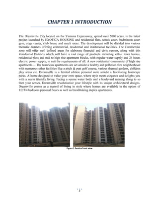
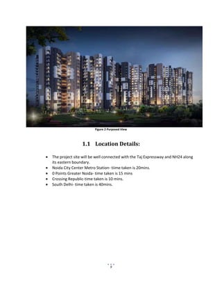
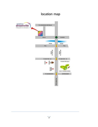
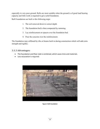
The document describes the construction of a residential tower by Mayank Walecha for their internship program. It includes an acknowledgements section thanking those involved in the project. It also includes an index outlining the contents of the report, which will cover quality control of building materials, structure work including the foundation, finishing work, and construction safety. The quality control chapter will discuss materials used like cement, aggregates, bricks, reinforcement bars, water, and admixtures.
![22
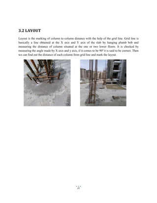
Figure 6 Layout plan
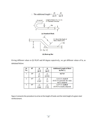
3.3 BAR BENDING SCHEDULE
Bar bending schedule (or schedule of bars) is a list of reinforcement bars a given RCC work
item, and is presented in a tabular form for easy visual reference. This table summarizes all the
needed particulars of bars – diameter, shape of bending, length of each bent and straight portions,
angles of bending, total length of each bar, and number of each type of bar. This information is a
great help in preparing an estimate of quantities.
Length of one hook = (4d ) + [(4d+ d )] – where, (4d+ d ) refers to the curved portion = 9d.
The additional length (la) that is introduced in the simple, straight end-to-end length of a
reinforcement bar due to being bent up at say 30o
to 60o
, but it is generally 45o
) = l1 – l2 = la
Where,](https://image.slidesharecdn.com/a22ce31d-a110-4693-abbb-a32df1eccf24-160813034513/85/Report-on-Residential-Construction-22-320.jpg)


![internship_presentation_2022-23[1] [Autosaved].pptx](https://cdn.slidesharecdn.com/ss_thumbnails/internshippresentation2022-231autosaved-230404152500-8f1b16b7-thumbnail.jpg?width=640&height=640&fit=bounds)


