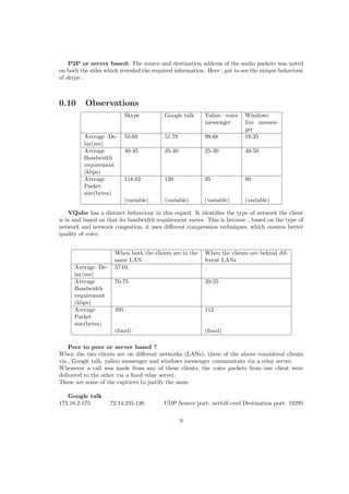
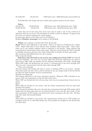
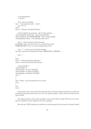
INDIAN ACADEMY OF SCIENCES
BANGALORE
SUMMER RESEARCH FELLOWSHIP - 2009
1
Ranjitha G kulkarni
II year B-Tech
Information Technology
NITK Surathkal
Countersigned by the guide
Prof K.V.S.Hari
Department of Electrical Communication Engineering
Indian Institute of Science
2
Study of parameters of quality of service of VoIP
clients
8 July 2009
Abstract
This document includes description of working of a VoIP system, its quality parameters and
how they affect the quality of service. Some networking concepts like Network Address Trans-
lation (NAT), network discovery technique (STUN) are also explained. The main part of the
document being the experiment conducted on some VoIP clients which were selected based on
their availability and popularity.The experiment section of the document includes description
of test conditions, how the parameters measured affect quality of service, technique used for
determining them along with the actual observations. This experiment was performed to study
the parameters that determine the quality of service of VoIP.Parameters measured include band-
width requirement, delay, size of audio packet.Other observations made were, how these VoIP
clients behave in different network conditions, if the connection established was P2P or server
based, how do they behave when behind a firewall. The VoIP clients under testing were Google
Talk, Skype, VQube,Windows Live Messenger and Yahoo Voice Messenger.Softwares like Wire-
shark, Bandwidth monitor,Net-peeker were used.The result obtained were analysed to draw some
interesting conclusion which may help one choose a VoIP client to cater to his/her purpose.This
document will help developers to further inprove their VoIP clients and give users an insight of
some technical details of the VoIP clients they use.
DESCRIPTION SECTION
0.1 Understanding VoIP
VoIP or Voice over Internet Protocol refers to transmission of voice over IP networks. VoIP
services convert your voice into a digital signal that travels over the Internet. The following
diagram explains in brief the modules of a VoIP system.
Figure 1: Block diagram of a VoIP system
Input to the A/D converter is an analog voice signal.
• The analog signal is digitized using a codec.
• The output of the codec is then sent to a packetizer which loads the binary code onto an
IP payload. Then it is sent over the network.
• On the other end the IP packets are input to the converter that strips of the IP header,
stores the payload, and then releases it in a constant bit stream to a codec.
• The codec converts back the bit stream into an analog signal.
0.2 Roles of different OSI layers in VoIP management
• Physical layer : It just deals with the physical and electrical connection between two
points , i.e., the transmission media , etc.,.
• Data-link layer : It deals with the reliable connection and local addressing between
adjacent nodes on the network. This layer puts the bits from the Physical layer into a
specific order, known as a frame. If noise or some other aberration occurs on the link,
an error control mechanism within that Data Link layer frame (such as a checksum) may
signal the problem. If a VoIP frame is faulty, some network monitoring systems will detect
those invalid frames and warn about the link being noisy.
• Network layer : This handles the routing and switching between two locations, and is
almost invariably implemented using the Internet Protocol. This layer also adds another
layer of addressing (the IP address) so that your station can be uniquely identified on the
global network. That IP address is contained within the Network layer unit of information,
called the packet. For VoIP networks, this addressing process may involve other systems.
One example might be the Domain Name Service, or DNS, which translates between host
names and IP addresses. Another might be Electronic Numbering, or ENUM, which trans-
lates between a telephone number (10 digits) and an IP address . So, if you find that
you can’t call a specific region of your network, and the Physical connections have tested
okay, then a scrambled address or addressing translation may be the culprit, and a protocol
analyzer is going to be required to sort this one out.
1
• Transport layer : This is responsible for the reliability of the end-to-end connection, and
is typically implemented with two protocols. The Transmission Control Protocol (TCP)
provides the greatest amount of reliability, but at a cost of additional overhead. The
User Datagram Protocol (UDP) cuts back on the reliability, but reduces the transmission
overhead. The unit of information for TCP is called a stream, while the unit of information
for UDP is called a datagram. Most VoIP networks use TCP to setup the connection (due
to its reliability), and then use UDP to actually transmit the VoIP packets (due to its
efficiency). Thus, you pay the price of overhead when it really counts (establishing the
connection), but subsequently cut back when the 20-to-40-millisecond voice packets start
flowing, under the premise that if you miss a few voice packets along the way, the end users
should still be able to make out the majority of the conversation.
• Session layer : This is responsible for the setting up and tearing down of the communi-
cation sessions.
• Presentation layer : It provides a mechanism of translating the sender’s data format
into a format that could be understood at the receiver. In conventional networks, data
encryption and data compression are good examples of Presentation layer functions. In
the VoIP world, the codec (coder/decoder) that makes the analog-to-digital conversion
provides an example of these capabilities.
• Application Layer : It provides functions that support the end user, such as voice dialing,
unified messaging, or integration between landline, cellular, and VoIP systems.
0.3 CODECs
Codecs perform the task of voice compression. Voice compression is important as it reduces the
size of the voice packets and thus reduces the bandwidth requirement for the communication.
Voice compression Data compression is a process whereby voice data is compressed to render
it less bulky for transfer. Compression software (called a codec) encodes the voice signals into
digital data that it compresses into lighter packets that are then transported over the Internet.
At the destination, these packets are decompressed and given their original size (though not
always), and converted back to analog voice again, so that the user can hear.
Codecs are not only used for compression, but also for encoding, which, simply said is the trans-
lation of analog voice into digital data that can be transmitted over IP networks. The quality
and efficiency of the compression software therefore has a big impact on the voice quality of VoIP
conversations. VoIP encodes and compresses voice data in a way such that some of the elements
of the audio stream is lost. This is called lossy compression. The loss is not a hard blow on voice
quality as much of it is on purpose. For instance, sounds that cannot be heard by the human
ear (of a frequency below or beyond that of the hearing spectrum) is discarded since it will be
useless. Also, silence is discarded. Minute fractions of audible sound is lost as well, but tiny bits
lost in voice does not prevent you from understanding what is being said.
2
Codec Bandwidth/kbps Comments
G.711 64 Delivers precise speech transmission. Very low processor require-
ments. Needs at least 128 kbps for two-way.
G.722 48/56/64 Adapts to varying compressions and bandwidth is conserved with
network congestion.
G.723.1 5.3/6.3 High compression with high quality audio. Can use with dial-up.
Lot of processor power.
G.726 16/24/32/40 An improved version of G.721 and G.723 (different from G.723.1)
G.729 8 Excellent bandwidth utilization. Error tolerant. License required.
GSM 13 High compression ratio. Free and available in many hardware and
software platforms. Same encoding is used in GSM cellphones
(improved versions are often used nowadays).
iLBC 15 Robust to packet loss.
Free Speex 2.15 / 44 Minimizes bandwidth usage by using variable bit rate.
0.4 Parameters affecting QOS
Some of the parameters that affect the quality of service of a VoIP system:
Bandwidth :
Bandwidth of the medium is the key factor for better voice quality in a VoIP system. Higher the
bandwidth of the medium, better the voice quality. Therefore for media with lower bandwidth
to serve a good quality VoIP, the bandwidth requirement of the VoIP client should be low.
Jitter:
Jitter is defined as a variation in the delay of received packets. At the sending side, packets are
sent in a continuous stream with the packets spaced evenly apart. Due to network congestion,
improper queuing, or configuration errors, this steady stream can become lumpy, or the delay
between each packet can vary instead of remaining constant.
Voice Traffic Priority There are two important components in prioritizing voice. The first is
classifying and marking interesting voice traffic. The second is prioritizing the marked interesting
voice traffic.
• Classification and marking :
In order to guarantee bandwidth for VoIP packets, a network device must be able to identify
the packets in all the IP traffic that flows through it. Network devices use the source and
destination IP address in the IP header, or the source and destination UDP port numbers
in the UDP header, to identify VoIP packets. This identification and grouping process is
called classification. Another simpler method of identification is setting the TOS ( type of
service ) byte in the IP header.
• Prioritizing:
After every hop in the network is able to classify and identify the VoIP packets (either
through port/address information or through the ToS byte), those hops then provide each
VoIP packet with the required QoS. At that point, configure special techniques to provide
priority queuing to make sure that large data packets do not interfere with voice data
transmission. This is usually required on slower WAN links where there is a high possibility
3
of congestion. Once all the interesting traffic is placed into QoS classes based on their QoS
requirements, provide bandwidth guarantees and priority servicing through an intelligent
output queuing mechanism. A priority queue is required for VoIP.
Latency:
Latency is the time between the moment a voice packet is transmitted and the moment it reaches
its destination. It of course leads to delay and finally to echo. It is caused by slow network links.
This is what leads to echo. Here are the effects of latency over voice quality:
• It slows down your phone conversations
• Untimeliness can results in overlapping noises, with one speaker interrupting the other
• Causes echo
• Disturbs synchronization between voice and other data types, especially during video con-
ferencing
VAD (voice activity detection)
A regular voice conversation consists of several moments of silence. A typical voice conversation
consists of 40 to 50 percent silence. Since there is not any voice going through the network for
40 percent of a voice call, some bandwidth can be saved by deploying VAD. With VAD, the
gateway looks out for gaps in speech. It replaces those gaps with comfort noise (background
noise). Thus, an amount of bandwidth is saved. However, there is a trade-off. There is a small
time (in order of milliseconds), before the codecs detect speech activity followed by a period of
silence. This small time results in the front-end clipping of received voice. To avoid activation
during very short pauses and to compensate for clipping, VAD waits approximately 200 ms after
speech stops before it stops transmission. Upon restarting transmission, it includes the previous
5 ms of speech along with the current speech. VAD disables itself on a call automatically if
ambient noise prevents it from distinguishing between speech and background noise. However,
if the bandwidth is not an issue, turn the VAD off.
Serialization delay:
When the priority queues are empty for some time then, packets other than voice packets will
be serviced. Due to this, some voice packets will have to wait for a significant amount of time.
Voice packets experience serialization delay when they have to wait behind larger data packets.
Issues related to QOS of a VoIP:
• Mouth-to-ear delay;
• Impact of erred frames (packets);
• Lost frames (packets);
• Variation of packet arrival time, jitter buffering;
• Prioritizing VoIP traffic over regular Internet and data services;
• Talker echo;
• Distortion;
• Sufficient bit rate capacity on interconnecting transmission media;
• Voice coding algorithm standardization;
4
• Optimized standard packet payload size;
• Packet overhead;
One of the major QOS issue is Choppy voice. Choppy voice quality is caused by voice packets
being either variably delayed or lost in the network. When a voice packet is delayed in reaching
its destination, the destination gateway has a loss of real-time information. In this event, the
destination gateway must predict what the content of the missed packet can possibly be. The
prediction leads to the received voice not having the same characteristics as the transmitted
voice. This leads to a received voice that sounds robotic. If a voice packet is delayed beyond the
prediction capability of a receiving gateway, the gateway leaves the real-time gap empty. With
nothing to fill up that gap at the receiving end, part of the transmitted speech is lost. This
results in choppy voice. Many of the choppy voice issues are resolved by making sure that the
voice packets are not very delayed (and more than that, not variably delayed). Sometimes, voice
activity detection (VAD) adds front-end clipping to a voice conversation. This is another cause
of choppy (or clipped) voice. Since the main cause is the jitter, this problem is tackled by making
use of jitter buffers. Jitter Buffer A jitter buffer is nothing but a queue of the voice packets a
VoIP client receives, arranged according to their timestamps. This solves the problem of variable
delay. A jitter buffer has a low watermark and a high watermark which represent the minimum
and maximum timestamp value of the voice packet received. All the voice packets are collected
and stored in the jitter buffer and delivered to the playout module so that sense can be made of
what is being played out.
0.5 NETWORK ADDRESS TRANSLATION
Network address translation (NAT) is the process of modifying network address information in
datagram packet headers while in transit across a traffic routing device for the purpose of remap-
ping a given address space into another.
Types of NAT
Full cone NAT, also known as one-to-one NAT
• Once an internal address (iAddr:port1) is mapped to an external address (eAddr:port2),
any packets from iAddr:port1 will be sent through eAddr:port2. Any external host can
send packets to iAddr:port1 by sending packets to eAddr:port2.
(Address) Restricted cone NAT
• Once an internal address (iAddr:port1) is mapped to an external address (eAddr:port2), any
packets from iAddr:port1 will be sent through eAddr:port2. An external host (hostAddr:any)
can send packets to iAddr:port1 by sending packets to eAddr:port2 only if iAddr:port1 had
previously sent a packet to hostAddr:any. ‘’any‘’ means the port number doesn’t matter.
Port-Restricted cone NAT
Like an (Address) Restricted cone NAT, but the restriction includes port numbers.
• Once an internal address (iAddr:port1) is mapped to an external address (eAddr:port2), any
packets from iAddr:port1 will be sent through eAddr:port2. An external host (hostAddr:port3)
can send packets to iAddr:port1 by sending packets to eAddr:port2 only if iAddr:port1 had
previously sent a packet to hostAddr:port3.
5
Symmetric NAT
• Each request from the same internal IP address and port to a specific destination IP
address and port is mapped to a unique external source IP address and port. If the same
internal host sends a packet even with the same source address and port but to a different
destination, a different mapping is used.
• Only an external host that receives a packet from an internal host can send a packet back.
0.6 Determinting the type of NAT a client is behind (STUN)
To determine the type of NAT a client is behind, the best solution is STUN (Simple Traversal
of UDP over NAT).
To achieve this let us carry out four tests which wil be explained below and based on the
observations conclusion can be made about the type of NAT a client is behind.
This includes two entities 1.A client and 2.A STUN server.
some of the important messages sent accross:
Client sends a message called Binding Request to the server requesting for a connection with
the server. Binding Request has following important attributes which concern us:
RESPONSEADDRESS attribute: Binding response which is sent by the server to the
client is sent to this address. If there is no address mentioned here, the response is sent back to
the source address and port of the Binding request.
CHANGEDADDRESS attribute: It contains two flags viz., change ip and change port.
If change ip flag is set, then the server responds to this request from a different source ip
address. Similar is the case with change port flag.
Binding Response is what is sent back by the server to the client in response to the Binding
request.
It has the attribute MAPPEDADDRESS: this address is the source ip and port from
where the request came to the server.
Let us assume that the ip of the client ip is ip1 and it communicates with the server via the
port p1. Let the server ip be ips1 and the port where these requests are sent is ps1. Ipx:px is
how the ip:port of the client is translated if it is behind a NAT (except for symmetric NAT).
1. In the first test, the client sends binding request to the server with CHANGEDAD-
DRESS flags not set. Depending on the response three conclusions can be made:
(a) NO RESPONSE: The client is not capable of UDP connectivity .
(b) Response has the Ip and port of the source itself in the MAPPEDADDRESS
attribute: The client is not behind any NAT.
(c) Response has different address ( ipx:px) in the MAPPEDADDRESS attribute:
The client is behind a NAT.
6
2. Next, the client sends binding request with both changed ip and changed port flags set.
Here the server sends response form a different ip and port.
(a) Response received at ipx:px : The client is behind a gull cone NAT.
(b) Response not received at ipx:px : The client is not behind a full cone NAT.
3. Next, to check if it is behind a symmetric NAT , the client sends a binding request to
another ip and port ips2:ps2 from where responses came in the previous tests.
(a) If the response has MAPPEDADDRESS as ipx:px , then the client is not behind
a symmetric NAT .
(b) If the MAPPEDADDRESS is different from ipx:px say ipx:py , then the client is
behind a SYMMETRIC NAT .
4. If the client is not behind a full cone or a symmetric NAT, then another binding request is
sent with only changed port flag set. Now the server sends the response only changing its
port and not the ip.
(a) If the response is received, then the client is behind restricted NAT.
(b) Else it is behind Port restricted NAT.
EXPERIMENT SECTION
0.7 Test Conditions
All the observations were made based on the calls over the internet between two windows XP
machines. The VoIP clients under consideration were:
1. Google Talk
2. Skype
3. VQube
4. Windows Live messenger
5. Yahoo Voice Messenger
Calls were made from one system to the other using every client under analysis. The two systems
were connected to two different LANs. One was behind a symmetric NAT and the other behind
a port restricted NAT. Parameters Recorded:
1. Bandwidth requirement.
2. Delay between two packets received.
3. Average packet size.
4. Behaviour behind firewall which does not allow UDP connectivity.
5. Does communication happen p2p or via a relay server.
7
0.8 How these parameters affect the QOS
Now let us look at how these parameters affect the quality of service of a VoIP call.
1. Bandwidth requirement
Lesser the bandwidth required to make a call, more is its clarity.
2. Delay between two successive packets received
Lesser the delay more is the clarity of what is spoken over the call.
3. Average packet size
Packet size is one more important characteristic of a voice packet. In case of a congested
network, any communication is prone to packet loss. If voice is packetized in large packets,
then a loss of even small number of packets is noticeable and it becomes difficult to decipher
what is being said. On the other hand if the packets are small, then loss of less number of
those will not affect the quality much.
4. Behaviour behind a firewall which does not allow UDP connectivity
If a client is behind a firewall that does not allow UDP traffic through the port in use, then
the client communicates through TCP packets. Use of TCP packets
5. Peer to peer or server based
It is always better if communication happens peer to peer. There might be degradation in
the quality of voice due to congestion at the server. Peer to peer connections avoid such
problems.
0.9 Testing technique
Tools used for testing
1. Bandwidth Monitor Pro - a software which displays the bandwidth usage of the network
adapter used.
2. Wireshark , a packet sniffing application .
3. Netpeeker ,a network monitor and control application.
Delay : Initially, calculated by taking difference between the time stamps of successive voice
packets and taking a=their average for every 20 packets and later figured out one feature of
wireshark , when we analyze the RTP stream it shows delta between two successive RTP packets
and the average of that can be recorded.
Bandwidth : The download rate shown by the bandwidth monitor.
Packet size : Size in bytes of the audio packets.
Behaviour behind firewall : UDP communication on the port used was blocked on one of
the machines and it was observed if the communication happened by TCP on both sides from
the server ( only if the communication was not peer to peer) or TCP on one side and UDP on
the other.
8
P2P or server based: The source and destination address of the audio packets was noted
on both the sides which revealed the required information. Here , got to see the unique behaviour
of skype .
0.10 Observations
Skype Google talk Yahoo voice
messenger
Windows
live messen-
ger
Average De-
lay(ms)
53.68 51.79 99.68 19.35
Average
Bandwidth
requirement
(kbps)
40-45 35-40 25-30 40-50
Average
Packet
size(bytes)
118.82 120 95 80
(variable) (variable) (variable) (variable)
VQube has a distinct behiaviour in this regard. It identifies the type of network the client
is in and based on that its bandwidth requirement varies. This is because , based on the type of
network and network congestion, it uses different compression techniques, which ensures better
quality of voice.
When both the clients are in the
same LAN
When the clients are behind dif-
ferent LANs
Average De-
lay(ms)
57.01
Average
Bandwidth
requirement
(kbps)
70-75 20-25
Average
Packet
size(bytes)
495 112
(fixed) (fixed)
Peer to peer or server based ?
When the two clients are on different networks (LANs), three of the above considered clients
viz., Google talk, yahoo messenger and windows messenger communicate via a relay server.
Whenever a call was made from any of these clients, the voice packets from one client were
delivered to the other via a fixed relay server.
These are some of the captures to justify the same.
Google talk
172.16.2.175 72.14.235.126 UDP Source port: netbill-cred Destination port: 19295
9
72.14.235.126 172.16.2.175 UDP Source port: 19295 Destination port:netbill-cred
72.16.235.126 is the Google talk server which relays packets between the two clients.
Yahoo
172.16.2.175 87.248.104.101 UDP Source port: 8051 Destination port: 53140
87.248.104.101 172.16.2.175 UDP Source port: 53140 Destination port: 8051
Yahoo does not use the same relay server every time we make a call. It has a fixed set of
addresses which act as servers. The mechanism by which it selects is unknown. It appears that
the servers are selected randomly for a given session.
In general the address of the Yahoo server is 87.248.104.x.
Similarly Windows messenger server address is 207.46.86.86.
VQube server address is 121.241.192.113 for all the calls.
Skype behaves quite differently in this matter. There is no fixed set of addresses for a Skype
server. Skype takes help of some selected client machines called super-nodes. These super-
nodes can be any random computer which is connected to the internet. Skype achieves p2p
communication with the help of these super-nodes. This lets a client behind any NAT or firewall
to establish connection with any other client behind NAT or firewall via these super-nodes.
The connection path differed from one call to another.
Refer to fig.2 for details.
Behaviour when Firewall on one system was configured to block UDP The Firewall
used was NetPeeker. For every test, the port which that particular application was using to
send/receive UDP traffic was blocked and the following observations were made. Google talk
When UDP traffic was blocked from one system, it communicated to the server through TCP
.But, the server communicated with the other client through UDP.
Yahoo voice messenger
This also behaves like Google talk when it comes to blocking UDP on one system. Another
observation made was that, when a call was already set up, any changes made to the firewall did
not affect the kind of packets used for communication.
Windows Live Messenger
This behaves differently in the above mentioned situation. Whenever UDP is blocked on one
system, TCP was transmitted on both the sides of the server.
When UDP was blocked after the call was setup, there was no communication between the two
clients.
Skype
When UDP was blocked on one system, both the clients communicated with the super-node
through TCP packets.
Next, firewall was disabled. But next call made also communicated through TCP packets which
implies that the skype client does not do network discovery every time the call is made. In fact
this transmission of TCP packets was observed for many consequent calls after this. All these
calls were made with firewall disabled.
VQube
When UDP was blocked on one system, the communication breaks and no TCP packets are
sent.Both clients try to send UDP packets but all the packets are dropped as the firewall does
not allow them.
10
0.11 Conclusion
1. Bandwidth requirement was the least in VQube when on internet.
2. Delay was observed to be minimum for a Windows live messenger call.
3. Peer to peer communication is best implemented in Skype.
4. Yahoo messenger and Google Talk work the best against firewall.
5. Network discovery and implementing appropriate techniques is best seen in VQube.
0.12 Other observations
1. It was observed if chat was encrypted on these IMs.
Encrypted Not encrypted
Skype Yahoo messenger
VQube Windows Live messenger
Google Talk
2. What protocols are used by these clients in setting up call
VoIP client protocol used
Google Talk XMPP , jabber and jingle for calls
Yahoo messenger Sip 2.0
Skype unknown*
VQube unknown*
3. Google Talk calls use UDP and TCP for alternate calls made between two clients on the
same LAN .
4. On VQube, whenever a call is setup the speaker volume goes down to zero.
0.13 Incomplete
Another important part of testing was to test if all the clients can get connected irrespective of
the type of NAT they are behind. To test this what was required was some software or peice
of code which does NAT simulation . After a significant amount of searching for such things,
iptables was found to be the most suitable package.
iptables is a project undertaken by netfilter. It is defined as follows: iptables is a generic
table structure for the definition of rulesets. Each rule within an IP table consists of a number
of classifiers (iptables matches) and one connected action (iptables target).
To acheive our goal, we need a linux machine on the network . This machine is configured as
a gateway by running the following script :
11
/etc/initd.gateway
! /bin/sh
If no rules, do nothing.
test ‘’ -f /etc/gateway.rules ‘’ ||exit 0
case ‘’$1‘’ in
start)
echo -n ‘’Turning on packet filtering:‘’
/sbin/modprobe ip masq ftp only if using ipchains
/sbin/modprobe iptable nat only if using iptables
/sbin/modprobe ipt MASQUERADE only if using iptables
/sbin/ipchains-restore </etc/ipchains.rules |exit 1
echo 1 >/proc/sys/net/ipv4/ip forward
for RedHat users, the above line is not needed if you have
FORWARD IPV4=true in /etc/sysconfig/network file
echo ‘’1‘’ >/proc/sys/net/ipv4/ip dynaddr
the above option is for Dynamic IP users (DHCP,PPP or BOOTP)
echo ‘’.‘’
;;
stop)
echo -n ‘’Turning off packet filtering:‘’
echo 0 >/proc/sys/net/ipv4/ip forward
/sbin/iptables -F
/sbin/iptables -X
/sbin/iptables -P input ACCEPT
/sbin/iptables -P output ACCEPT
/sbin/iptables -P forward ACCEPT
echo ‘’.‘’
;;
)
echo ‘’Usage: /etc/init.d/gateway start ||stop‘’
exit 1
;;
esac
exit 0
The required rules can be inserted in gateway.rules. This file contains nothing but a collection
of iptables commands with rules to let in or out specific packets. These rules vary based on the
type of NAT.
The default gateway of the other machine on the same LAN on which NAT was to be simu-
lated is changed to the ip address of the linux machine.
But this part (NAT simulation) could not be tested because the the network is already behind
12
a port restricted NAT. This NAT can not be disabled as is set at the BSNL’s common de-
fault gateway 192.168.1.1 . Every machine connected to the internet through BSNL broadband
connection has to pass through the same gateway and thus is behind a port restricted NAT .
13
Figure 2: different patterns of connection of skype client
14

Report

  • 1.
    INDIAN ACADEMY OFSCIENCES BANGALORE SUMMER RESEARCH FELLOWSHIP - 2009 1
  • 2.
    Ranjitha G kulkarni IIyear B-Tech Information Technology NITK Surathkal Countersigned by the guide Prof K.V.S.Hari Department of Electrical Communication Engineering Indian Institute of Science 2
  • 3.
    Study of parametersof quality of service of VoIP clients 8 July 2009
  • 4.
    Abstract This document includesdescription of working of a VoIP system, its quality parameters and how they affect the quality of service. Some networking concepts like Network Address Trans- lation (NAT), network discovery technique (STUN) are also explained. The main part of the document being the experiment conducted on some VoIP clients which were selected based on their availability and popularity.The experiment section of the document includes description of test conditions, how the parameters measured affect quality of service, technique used for determining them along with the actual observations. This experiment was performed to study the parameters that determine the quality of service of VoIP.Parameters measured include band- width requirement, delay, size of audio packet.Other observations made were, how these VoIP clients behave in different network conditions, if the connection established was P2P or server based, how do they behave when behind a firewall. The VoIP clients under testing were Google Talk, Skype, VQube,Windows Live Messenger and Yahoo Voice Messenger.Softwares like Wire- shark, Bandwidth monitor,Net-peeker were used.The result obtained were analysed to draw some interesting conclusion which may help one choose a VoIP client to cater to his/her purpose.This document will help developers to further inprove their VoIP clients and give users an insight of some technical details of the VoIP clients they use.
  • 5.
    DESCRIPTION SECTION 0.1 UnderstandingVoIP VoIP or Voice over Internet Protocol refers to transmission of voice over IP networks. VoIP services convert your voice into a digital signal that travels over the Internet. The following diagram explains in brief the modules of a VoIP system. Figure 1: Block diagram of a VoIP system Input to the A/D converter is an analog voice signal. • The analog signal is digitized using a codec. • The output of the codec is then sent to a packetizer which loads the binary code onto an IP payload. Then it is sent over the network. • On the other end the IP packets are input to the converter that strips of the IP header, stores the payload, and then releases it in a constant bit stream to a codec. • The codec converts back the bit stream into an analog signal. 0.2 Roles of different OSI layers in VoIP management • Physical layer : It just deals with the physical and electrical connection between two points , i.e., the transmission media , etc.,. • Data-link layer : It deals with the reliable connection and local addressing between adjacent nodes on the network. This layer puts the bits from the Physical layer into a specific order, known as a frame. If noise or some other aberration occurs on the link, an error control mechanism within that Data Link layer frame (such as a checksum) may signal the problem. If a VoIP frame is faulty, some network monitoring systems will detect those invalid frames and warn about the link being noisy. • Network layer : This handles the routing and switching between two locations, and is almost invariably implemented using the Internet Protocol. This layer also adds another layer of addressing (the IP address) so that your station can be uniquely identified on the global network. That IP address is contained within the Network layer unit of information, called the packet. For VoIP networks, this addressing process may involve other systems. One example might be the Domain Name Service, or DNS, which translates between host names and IP addresses. Another might be Electronic Numbering, or ENUM, which trans- lates between a telephone number (10 digits) and an IP address . So, if you find that you can’t call a specific region of your network, and the Physical connections have tested okay, then a scrambled address or addressing translation may be the culprit, and a protocol analyzer is going to be required to sort this one out. 1
  • 6.
    • Transport layer: This is responsible for the reliability of the end-to-end connection, and is typically implemented with two protocols. The Transmission Control Protocol (TCP) provides the greatest amount of reliability, but at a cost of additional overhead. The User Datagram Protocol (UDP) cuts back on the reliability, but reduces the transmission overhead. The unit of information for TCP is called a stream, while the unit of information for UDP is called a datagram. Most VoIP networks use TCP to setup the connection (due to its reliability), and then use UDP to actually transmit the VoIP packets (due to its efficiency). Thus, you pay the price of overhead when it really counts (establishing the connection), but subsequently cut back when the 20-to-40-millisecond voice packets start flowing, under the premise that if you miss a few voice packets along the way, the end users should still be able to make out the majority of the conversation. • Session layer : This is responsible for the setting up and tearing down of the communi- cation sessions. • Presentation layer : It provides a mechanism of translating the sender’s data format into a format that could be understood at the receiver. In conventional networks, data encryption and data compression are good examples of Presentation layer functions. In the VoIP world, the codec (coder/decoder) that makes the analog-to-digital conversion provides an example of these capabilities. • Application Layer : It provides functions that support the end user, such as voice dialing, unified messaging, or integration between landline, cellular, and VoIP systems. 0.3 CODECs Codecs perform the task of voice compression. Voice compression is important as it reduces the size of the voice packets and thus reduces the bandwidth requirement for the communication. Voice compression Data compression is a process whereby voice data is compressed to render it less bulky for transfer. Compression software (called a codec) encodes the voice signals into digital data that it compresses into lighter packets that are then transported over the Internet. At the destination, these packets are decompressed and given their original size (though not always), and converted back to analog voice again, so that the user can hear. Codecs are not only used for compression, but also for encoding, which, simply said is the trans- lation of analog voice into digital data that can be transmitted over IP networks. The quality and efficiency of the compression software therefore has a big impact on the voice quality of VoIP conversations. VoIP encodes and compresses voice data in a way such that some of the elements of the audio stream is lost. This is called lossy compression. The loss is not a hard blow on voice quality as much of it is on purpose. For instance, sounds that cannot be heard by the human ear (of a frequency below or beyond that of the hearing spectrum) is discarded since it will be useless. Also, silence is discarded. Minute fractions of audible sound is lost as well, but tiny bits lost in voice does not prevent you from understanding what is being said. 2
  • 7.
    Codec Bandwidth/kbps Comments G.71164 Delivers precise speech transmission. Very low processor require- ments. Needs at least 128 kbps for two-way. G.722 48/56/64 Adapts to varying compressions and bandwidth is conserved with network congestion. G.723.1 5.3/6.3 High compression with high quality audio. Can use with dial-up. Lot of processor power. G.726 16/24/32/40 An improved version of G.721 and G.723 (different from G.723.1) G.729 8 Excellent bandwidth utilization. Error tolerant. License required. GSM 13 High compression ratio. Free and available in many hardware and software platforms. Same encoding is used in GSM cellphones (improved versions are often used nowadays). iLBC 15 Robust to packet loss. Free Speex 2.15 / 44 Minimizes bandwidth usage by using variable bit rate. 0.4 Parameters affecting QOS Some of the parameters that affect the quality of service of a VoIP system: Bandwidth : Bandwidth of the medium is the key factor for better voice quality in a VoIP system. Higher the bandwidth of the medium, better the voice quality. Therefore for media with lower bandwidth to serve a good quality VoIP, the bandwidth requirement of the VoIP client should be low. Jitter: Jitter is defined as a variation in the delay of received packets. At the sending side, packets are sent in a continuous stream with the packets spaced evenly apart. Due to network congestion, improper queuing, or configuration errors, this steady stream can become lumpy, or the delay between each packet can vary instead of remaining constant. Voice Traffic Priority There are two important components in prioritizing voice. The first is classifying and marking interesting voice traffic. The second is prioritizing the marked interesting voice traffic. • Classification and marking : In order to guarantee bandwidth for VoIP packets, a network device must be able to identify the packets in all the IP traffic that flows through it. Network devices use the source and destination IP address in the IP header, or the source and destination UDP port numbers in the UDP header, to identify VoIP packets. This identification and grouping process is called classification. Another simpler method of identification is setting the TOS ( type of service ) byte in the IP header. • Prioritizing: After every hop in the network is able to classify and identify the VoIP packets (either through port/address information or through the ToS byte), those hops then provide each VoIP packet with the required QoS. At that point, configure special techniques to provide priority queuing to make sure that large data packets do not interfere with voice data transmission. This is usually required on slower WAN links where there is a high possibility 3
  • 8.
    of congestion. Onceall the interesting traffic is placed into QoS classes based on their QoS requirements, provide bandwidth guarantees and priority servicing through an intelligent output queuing mechanism. A priority queue is required for VoIP. Latency: Latency is the time between the moment a voice packet is transmitted and the moment it reaches its destination. It of course leads to delay and finally to echo. It is caused by slow network links. This is what leads to echo. Here are the effects of latency over voice quality: • It slows down your phone conversations • Untimeliness can results in overlapping noises, with one speaker interrupting the other • Causes echo • Disturbs synchronization between voice and other data types, especially during video con- ferencing VAD (voice activity detection) A regular voice conversation consists of several moments of silence. A typical voice conversation consists of 40 to 50 percent silence. Since there is not any voice going through the network for 40 percent of a voice call, some bandwidth can be saved by deploying VAD. With VAD, the gateway looks out for gaps in speech. It replaces those gaps with comfort noise (background noise). Thus, an amount of bandwidth is saved. However, there is a trade-off. There is a small time (in order of milliseconds), before the codecs detect speech activity followed by a period of silence. This small time results in the front-end clipping of received voice. To avoid activation during very short pauses and to compensate for clipping, VAD waits approximately 200 ms after speech stops before it stops transmission. Upon restarting transmission, it includes the previous 5 ms of speech along with the current speech. VAD disables itself on a call automatically if ambient noise prevents it from distinguishing between speech and background noise. However, if the bandwidth is not an issue, turn the VAD off. Serialization delay: When the priority queues are empty for some time then, packets other than voice packets will be serviced. Due to this, some voice packets will have to wait for a significant amount of time. Voice packets experience serialization delay when they have to wait behind larger data packets. Issues related to QOS of a VoIP: • Mouth-to-ear delay; • Impact of erred frames (packets); • Lost frames (packets); • Variation of packet arrival time, jitter buffering; • Prioritizing VoIP traffic over regular Internet and data services; • Talker echo; • Distortion; • Sufficient bit rate capacity on interconnecting transmission media; • Voice coding algorithm standardization; 4
  • 9.
    • Optimized standardpacket payload size; • Packet overhead; One of the major QOS issue is Choppy voice. Choppy voice quality is caused by voice packets being either variably delayed or lost in the network. When a voice packet is delayed in reaching its destination, the destination gateway has a loss of real-time information. In this event, the destination gateway must predict what the content of the missed packet can possibly be. The prediction leads to the received voice not having the same characteristics as the transmitted voice. This leads to a received voice that sounds robotic. If a voice packet is delayed beyond the prediction capability of a receiving gateway, the gateway leaves the real-time gap empty. With nothing to fill up that gap at the receiving end, part of the transmitted speech is lost. This results in choppy voice. Many of the choppy voice issues are resolved by making sure that the voice packets are not very delayed (and more than that, not variably delayed). Sometimes, voice activity detection (VAD) adds front-end clipping to a voice conversation. This is another cause of choppy (or clipped) voice. Since the main cause is the jitter, this problem is tackled by making use of jitter buffers. Jitter Buffer A jitter buffer is nothing but a queue of the voice packets a VoIP client receives, arranged according to their timestamps. This solves the problem of variable delay. A jitter buffer has a low watermark and a high watermark which represent the minimum and maximum timestamp value of the voice packet received. All the voice packets are collected and stored in the jitter buffer and delivered to the playout module so that sense can be made of what is being played out. 0.5 NETWORK ADDRESS TRANSLATION Network address translation (NAT) is the process of modifying network address information in datagram packet headers while in transit across a traffic routing device for the purpose of remap- ping a given address space into another. Types of NAT Full cone NAT, also known as one-to-one NAT • Once an internal address (iAddr:port1) is mapped to an external address (eAddr:port2), any packets from iAddr:port1 will be sent through eAddr:port2. Any external host can send packets to iAddr:port1 by sending packets to eAddr:port2. (Address) Restricted cone NAT • Once an internal address (iAddr:port1) is mapped to an external address (eAddr:port2), any packets from iAddr:port1 will be sent through eAddr:port2. An external host (hostAddr:any) can send packets to iAddr:port1 by sending packets to eAddr:port2 only if iAddr:port1 had previously sent a packet to hostAddr:any. ‘’any‘’ means the port number doesn’t matter. Port-Restricted cone NAT Like an (Address) Restricted cone NAT, but the restriction includes port numbers. • Once an internal address (iAddr:port1) is mapped to an external address (eAddr:port2), any packets from iAddr:port1 will be sent through eAddr:port2. An external host (hostAddr:port3) can send packets to iAddr:port1 by sending packets to eAddr:port2 only if iAddr:port1 had previously sent a packet to hostAddr:port3. 5
  • 10.
    Symmetric NAT • Eachrequest from the same internal IP address and port to a specific destination IP address and port is mapped to a unique external source IP address and port. If the same internal host sends a packet even with the same source address and port but to a different destination, a different mapping is used. • Only an external host that receives a packet from an internal host can send a packet back. 0.6 Determinting the type of NAT a client is behind (STUN) To determine the type of NAT a client is behind, the best solution is STUN (Simple Traversal of UDP over NAT). To achieve this let us carry out four tests which wil be explained below and based on the observations conclusion can be made about the type of NAT a client is behind. This includes two entities 1.A client and 2.A STUN server. some of the important messages sent accross: Client sends a message called Binding Request to the server requesting for a connection with the server. Binding Request has following important attributes which concern us: RESPONSEADDRESS attribute: Binding response which is sent by the server to the client is sent to this address. If there is no address mentioned here, the response is sent back to the source address and port of the Binding request. CHANGEDADDRESS attribute: It contains two flags viz., change ip and change port. If change ip flag is set, then the server responds to this request from a different source ip address. Similar is the case with change port flag. Binding Response is what is sent back by the server to the client in response to the Binding request. It has the attribute MAPPEDADDRESS: this address is the source ip and port from where the request came to the server. Let us assume that the ip of the client ip is ip1 and it communicates with the server via the port p1. Let the server ip be ips1 and the port where these requests are sent is ps1. Ipx:px is how the ip:port of the client is translated if it is behind a NAT (except for symmetric NAT). 1. In the first test, the client sends binding request to the server with CHANGEDAD- DRESS flags not set. Depending on the response three conclusions can be made: (a) NO RESPONSE: The client is not capable of UDP connectivity . (b) Response has the Ip and port of the source itself in the MAPPEDADDRESS attribute: The client is not behind any NAT. (c) Response has different address ( ipx:px) in the MAPPEDADDRESS attribute: The client is behind a NAT. 6
  • 11.
    2. Next, theclient sends binding request with both changed ip and changed port flags set. Here the server sends response form a different ip and port. (a) Response received at ipx:px : The client is behind a gull cone NAT. (b) Response not received at ipx:px : The client is not behind a full cone NAT. 3. Next, to check if it is behind a symmetric NAT , the client sends a binding request to another ip and port ips2:ps2 from where responses came in the previous tests. (a) If the response has MAPPEDADDRESS as ipx:px , then the client is not behind a symmetric NAT . (b) If the MAPPEDADDRESS is different from ipx:px say ipx:py , then the client is behind a SYMMETRIC NAT . 4. If the client is not behind a full cone or a symmetric NAT, then another binding request is sent with only changed port flag set. Now the server sends the response only changing its port and not the ip. (a) If the response is received, then the client is behind restricted NAT. (b) Else it is behind Port restricted NAT. EXPERIMENT SECTION 0.7 Test Conditions All the observations were made based on the calls over the internet between two windows XP machines. The VoIP clients under consideration were: 1. Google Talk 2. Skype 3. VQube 4. Windows Live messenger 5. Yahoo Voice Messenger Calls were made from one system to the other using every client under analysis. The two systems were connected to two different LANs. One was behind a symmetric NAT and the other behind a port restricted NAT. Parameters Recorded: 1. Bandwidth requirement. 2. Delay between two packets received. 3. Average packet size. 4. Behaviour behind firewall which does not allow UDP connectivity. 5. Does communication happen p2p or via a relay server. 7
  • 12.
    0.8 How theseparameters affect the QOS Now let us look at how these parameters affect the quality of service of a VoIP call. 1. Bandwidth requirement Lesser the bandwidth required to make a call, more is its clarity. 2. Delay between two successive packets received Lesser the delay more is the clarity of what is spoken over the call. 3. Average packet size Packet size is one more important characteristic of a voice packet. In case of a congested network, any communication is prone to packet loss. If voice is packetized in large packets, then a loss of even small number of packets is noticeable and it becomes difficult to decipher what is being said. On the other hand if the packets are small, then loss of less number of those will not affect the quality much. 4. Behaviour behind a firewall which does not allow UDP connectivity If a client is behind a firewall that does not allow UDP traffic through the port in use, then the client communicates through TCP packets. Use of TCP packets 5. Peer to peer or server based It is always better if communication happens peer to peer. There might be degradation in the quality of voice due to congestion at the server. Peer to peer connections avoid such problems. 0.9 Testing technique Tools used for testing 1. Bandwidth Monitor Pro - a software which displays the bandwidth usage of the network adapter used. 2. Wireshark , a packet sniffing application . 3. Netpeeker ,a network monitor and control application. Delay : Initially, calculated by taking difference between the time stamps of successive voice packets and taking a=their average for every 20 packets and later figured out one feature of wireshark , when we analyze the RTP stream it shows delta between two successive RTP packets and the average of that can be recorded. Bandwidth : The download rate shown by the bandwidth monitor. Packet size : Size in bytes of the audio packets. Behaviour behind firewall : UDP communication on the port used was blocked on one of the machines and it was observed if the communication happened by TCP on both sides from the server ( only if the communication was not peer to peer) or TCP on one side and UDP on the other. 8
  • 13.
    P2P or serverbased: The source and destination address of the audio packets was noted on both the sides which revealed the required information. Here , got to see the unique behaviour of skype . 0.10 Observations Skype Google talk Yahoo voice messenger Windows live messen- ger Average De- lay(ms) 53.68 51.79 99.68 19.35 Average Bandwidth requirement (kbps) 40-45 35-40 25-30 40-50 Average Packet size(bytes) 118.82 120 95 80 (variable) (variable) (variable) (variable) VQube has a distinct behiaviour in this regard. It identifies the type of network the client is in and based on that its bandwidth requirement varies. This is because , based on the type of network and network congestion, it uses different compression techniques, which ensures better quality of voice. When both the clients are in the same LAN When the clients are behind dif- ferent LANs Average De- lay(ms) 57.01 Average Bandwidth requirement (kbps) 70-75 20-25 Average Packet size(bytes) 495 112 (fixed) (fixed) Peer to peer or server based ? When the two clients are on different networks (LANs), three of the above considered clients viz., Google talk, yahoo messenger and windows messenger communicate via a relay server. Whenever a call was made from any of these clients, the voice packets from one client were delivered to the other via a fixed relay server. These are some of the captures to justify the same. Google talk 172.16.2.175 72.14.235.126 UDP Source port: netbill-cred Destination port: 19295 9
  • 14.
    72.14.235.126 172.16.2.175 UDPSource port: 19295 Destination port:netbill-cred 72.16.235.126 is the Google talk server which relays packets between the two clients. Yahoo 172.16.2.175 87.248.104.101 UDP Source port: 8051 Destination port: 53140 87.248.104.101 172.16.2.175 UDP Source port: 53140 Destination port: 8051 Yahoo does not use the same relay server every time we make a call. It has a fixed set of addresses which act as servers. The mechanism by which it selects is unknown. It appears that the servers are selected randomly for a given session. In general the address of the Yahoo server is 87.248.104.x. Similarly Windows messenger server address is 207.46.86.86. VQube server address is 121.241.192.113 for all the calls. Skype behaves quite differently in this matter. There is no fixed set of addresses for a Skype server. Skype takes help of some selected client machines called super-nodes. These super- nodes can be any random computer which is connected to the internet. Skype achieves p2p communication with the help of these super-nodes. This lets a client behind any NAT or firewall to establish connection with any other client behind NAT or firewall via these super-nodes. The connection path differed from one call to another. Refer to fig.2 for details. Behaviour when Firewall on one system was configured to block UDP The Firewall used was NetPeeker. For every test, the port which that particular application was using to send/receive UDP traffic was blocked and the following observations were made. Google talk When UDP traffic was blocked from one system, it communicated to the server through TCP .But, the server communicated with the other client through UDP. Yahoo voice messenger This also behaves like Google talk when it comes to blocking UDP on one system. Another observation made was that, when a call was already set up, any changes made to the firewall did not affect the kind of packets used for communication. Windows Live Messenger This behaves differently in the above mentioned situation. Whenever UDP is blocked on one system, TCP was transmitted on both the sides of the server. When UDP was blocked after the call was setup, there was no communication between the two clients. Skype When UDP was blocked on one system, both the clients communicated with the super-node through TCP packets. Next, firewall was disabled. But next call made also communicated through TCP packets which implies that the skype client does not do network discovery every time the call is made. In fact this transmission of TCP packets was observed for many consequent calls after this. All these calls were made with firewall disabled. VQube When UDP was blocked on one system, the communication breaks and no TCP packets are sent.Both clients try to send UDP packets but all the packets are dropped as the firewall does not allow them. 10
  • 15.
    0.11 Conclusion 1. Bandwidthrequirement was the least in VQube when on internet. 2. Delay was observed to be minimum for a Windows live messenger call. 3. Peer to peer communication is best implemented in Skype. 4. Yahoo messenger and Google Talk work the best against firewall. 5. Network discovery and implementing appropriate techniques is best seen in VQube. 0.12 Other observations 1. It was observed if chat was encrypted on these IMs. Encrypted Not encrypted Skype Yahoo messenger VQube Windows Live messenger Google Talk 2. What protocols are used by these clients in setting up call VoIP client protocol used Google Talk XMPP , jabber and jingle for calls Yahoo messenger Sip 2.0 Skype unknown* VQube unknown* 3. Google Talk calls use UDP and TCP for alternate calls made between two clients on the same LAN . 4. On VQube, whenever a call is setup the speaker volume goes down to zero. 0.13 Incomplete Another important part of testing was to test if all the clients can get connected irrespective of the type of NAT they are behind. To test this what was required was some software or peice of code which does NAT simulation . After a significant amount of searching for such things, iptables was found to be the most suitable package. iptables is a project undertaken by netfilter. It is defined as follows: iptables is a generic table structure for the definition of rulesets. Each rule within an IP table consists of a number of classifiers (iptables matches) and one connected action (iptables target). To acheive our goal, we need a linux machine on the network . This machine is configured as a gateway by running the following script : 11
  • 16.
    /etc/initd.gateway ! /bin/sh If norules, do nothing. test ‘’ -f /etc/gateway.rules ‘’ ||exit 0 case ‘’$1‘’ in start) echo -n ‘’Turning on packet filtering:‘’ /sbin/modprobe ip masq ftp only if using ipchains /sbin/modprobe iptable nat only if using iptables /sbin/modprobe ipt MASQUERADE only if using iptables /sbin/ipchains-restore </etc/ipchains.rules |exit 1 echo 1 >/proc/sys/net/ipv4/ip forward for RedHat users, the above line is not needed if you have FORWARD IPV4=true in /etc/sysconfig/network file echo ‘’1‘’ >/proc/sys/net/ipv4/ip dynaddr the above option is for Dynamic IP users (DHCP,PPP or BOOTP) echo ‘’.‘’ ;; stop) echo -n ‘’Turning off packet filtering:‘’ echo 0 >/proc/sys/net/ipv4/ip forward /sbin/iptables -F /sbin/iptables -X /sbin/iptables -P input ACCEPT /sbin/iptables -P output ACCEPT /sbin/iptables -P forward ACCEPT echo ‘’.‘’ ;; ) echo ‘’Usage: /etc/init.d/gateway start ||stop‘’ exit 1 ;; esac exit 0 The required rules can be inserted in gateway.rules. This file contains nothing but a collection of iptables commands with rules to let in or out specific packets. These rules vary based on the type of NAT. The default gateway of the other machine on the same LAN on which NAT was to be simu- lated is changed to the ip address of the linux machine. But this part (NAT simulation) could not be tested because the the network is already behind 12
  • 17.
    a port restrictedNAT. This NAT can not be disabled as is set at the BSNL’s common de- fault gateway 192.168.1.1 . Every machine connected to the internet through BSNL broadband connection has to pass through the same gateway and thus is behind a port restricted NAT . 13
  • 18.
    Figure 2: differentpatterns of connection of skype client 14