
More Related Content
What's hot
What's hot (20)
Recently uploaded
Recently uploaded (20)
Reduction & Enlargement of Plane Figures
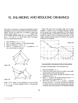
- 1. 15. ENLARGING AND REDUCING DRAWINGS Very often it is necessary to enlarge and sometimes to reduce mouldings in size but it is also essential to retain their similarity. Figures 134 and 135 show how it is possible to reduce and enlarge irregular figures. Let a - b - c - d - e (figure 134) be an irregular pentagon which has to be reduced in size so that a - b is now a - b'. All the other sides of the figure are to be reduced proportionately. 1. Draw the figure a - b - c - d - e. 2. On a - b mark b' making a - b' the required length. 3. Draw the diagonals a - c and a-d. 4. Draw b' - c' parallel to b - c, c' - d' parallel to c - d etc., until the figure is complete. c Figure 134 Figure 135 Figure 135 is similar to the preceding one, but this time a - b - c - d - e has been enlarged so that a - b now becomes a - b' in length. 40 Figure 136 shows how an irregular shape can be either enlarged or reduced in size. The original drawing is divided up into squares and a similar quadrilateral to fit the reduced or enlarged drawing is constructed and divided into a similar number of squares. Then, by following the pattern of the original drawing, using the squares for reference, the required drawing can be completed. Figure 136 -+ ---j-~-+-~-13 +----t-,I-I 5 2 3 4 5 6 2 3 4 5 6 ENLARGEMENT AND REDUCTION OF MOULDINGS To enlarge a moulding (figure 137) in thickness only: 1. Draw the moulding a - b - c. 2. Project the various points across the width of the mould- ing downwards and beyond the base line. 3. Project the various points through the thickness of the moulding across to a-c. 4. Make a - e equal to the required thickness. Draw c - e and the lines from f and g parallel to c - e. 5. With centre a and radii a - f', a - g' and a - e describe the arcs round to a-d. Project the points thus obtained to intersect with the vertical lines brought down from the moulding to give various points on the required moulding. A. B. Emary, A Comprehensive Practical Geometry for Builders © A. B. Emary 1981
- 2. Enlarging and reducing drawings 41 Figure 137 Enlargement in width and thickness Figure 138 shows how a moulding can be increased in width as well as in thickness. Let a - b' - c' be the moulding and a - b the required thickness and a - c the required width. 1. Draw the given moulding and also a - b and a - c of the required moulding. 2. Draw b' - b and the other lines through the thickness of the moulding parallel to b' - b. And similarly draw c' - c and the other lines across the width parallel to c' - c. 3. Lines from points on a - b should be drawn across to meet lines brought down from a - c to give points on the required moulding. CO Figure 138 Proportional reduction Figure 139 shows how a moulding can be reduced proportion- ately. Let 0 - 1 - 2 - 3 - 4 - 5 - 6 be the given moulding and 0' - 6' be the depth of the required moulding. 1. Draw the given moulding and some distance away draw 0' - 6' parallel to 0 - 6. 2. Draw a line from 0, through 0' in the direction of 0". 3. Draw another line, from 6, through 6' to meet the other in 0". 4. Draw other lines from 1, 2, 3 etc., to meet in 0". 5. Draw 0' - 2' parallel to 0 - 2, 2' - 3' parallel to 2 - 3 etc., to complete the required moulding. As it would be difficult to position accurately point number 4 in the required moulding point number 1 has been placed on the given moulding immediately above 4. This will enable 4' to be placed accurately. Figure 139 6 5 ARCHITRAVES AROUND A DOORWAY Figure 140 shows how the shapes of two architraves around a doorway, unequal in width can be decided. givlZn mitre a Figure 140