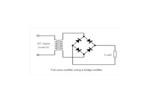
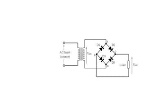
6.Half wave rectifier &Full
wave Bridge rectifier
Aim: To design half wave and Full wave Bridge rectifiers and analyze
their performance with in terms of ripple factor
https://www.electrical4u.com/half-wave-rectifiers/
https://www.circuitstoday.com/half-wave-rectifiers
https://www.electronics-notes.com/articles/analogue_circuits/diode-rectifiers/full-wave-rectifier-circuits.php
Reference Link
A half wave rectifier is defined as a type of rectifier that only allows one half-cycle of
an AC voltage waveform to pass, blocking the other half-cycle.
Half-wave rectifiers are used to convert AC voltage to DC voltage, and only require a
single diode to construct.
When a standard AC waveform is passed through a half-wave rectifier, only half of
the AC waveform remains.
Half-wave rectifiers only allow one half-cycle (positive or negative half-cycle) of the
AC voltage through and will block the other half-cycle on the DC side, as seen below.
a complete half-wave rectifier circuit consists of 3 main
parts:
1.A transformer
2.A resistive load
3.A diode
First, a high AC voltage is
applied to the to the primary
side of the step-down
transformer and
we will get a low voltage at the
secondary winding which will
be applied to the diode.
During the positive half cycle of the AC voltage, the diode
will be forward biased and the current flows through the
diode.
During the negative half cycle of the AC voltage, the
diode will be reverse biased and the flow of current will
be blocked.
The final output voltage waveform on the secondary side
(DC) is shown in figure 3 above.
We’ll focus on the secondary side of the circuit. If we
replace the secondary transformer coils with a source
voltage, we can simplify the circuit diagram of the half-
wave rectifier as
For the positive half cycle of the AC source voltage, the
equivalent circuit effectively becomes:
the negative half cycle of the AC source voltage, the
equivalent circuit becomes:
CALCULATIONS: Theoretical calculations for Ripple factor of Half wave
Rectifier:-
Sr No Load
Resistance(kΩ)
Input
voltage
(VPP)
Vm (V) VDC Vrms Ripple
Factor
01 1
02 5
03 10
Observation Table for HWR &FWR for Bridge
Theoretical calculations for Ripple factor of Full wave Rectifier:-

Half wave rectifier.pptx

  • 1.
    6.Half wave rectifier&Full wave Bridge rectifier
  • 2.
    Aim: To designhalf wave and Full wave Bridge rectifiers and analyze their performance with in terms of ripple factor
  • 3.
  • 4.
    A half waverectifier is defined as a type of rectifier that only allows one half-cycle of an AC voltage waveform to pass, blocking the other half-cycle. Half-wave rectifiers are used to convert AC voltage to DC voltage, and only require a single diode to construct. When a standard AC waveform is passed through a half-wave rectifier, only half of the AC waveform remains. Half-wave rectifiers only allow one half-cycle (positive or negative half-cycle) of the AC voltage through and will block the other half-cycle on the DC side, as seen below.
  • 5.
    a complete half-waverectifier circuit consists of 3 main parts: 1.A transformer 2.A resistive load 3.A diode First, a high AC voltage is applied to the to the primary side of the step-down transformer and we will get a low voltage at the secondary winding which will be applied to the diode. During the positive half cycle of the AC voltage, the diode will be forward biased and the current flows through the diode. During the negative half cycle of the AC voltage, the diode will be reverse biased and the flow of current will be blocked. The final output voltage waveform on the secondary side (DC) is shown in figure 3 above.
  • 6.
    We’ll focus onthe secondary side of the circuit. If we replace the secondary transformer coils with a source voltage, we can simplify the circuit diagram of the half- wave rectifier as
  • 7.
    For the positivehalf cycle of the AC source voltage, the equivalent circuit effectively becomes: the negative half cycle of the AC source voltage, the equivalent circuit becomes:
  • 9.
    CALCULATIONS: Theoretical calculationsfor Ripple factor of Half wave Rectifier:-
  • 10.
    Sr No Load Resistance(kΩ) Input voltage (VPP) Vm(V) VDC Vrms Ripple Factor 01 1 02 5 03 10 Observation Table for HWR &FWR for Bridge
  • 13.
    Theoretical calculations forRipple factor of Full wave Rectifier:-