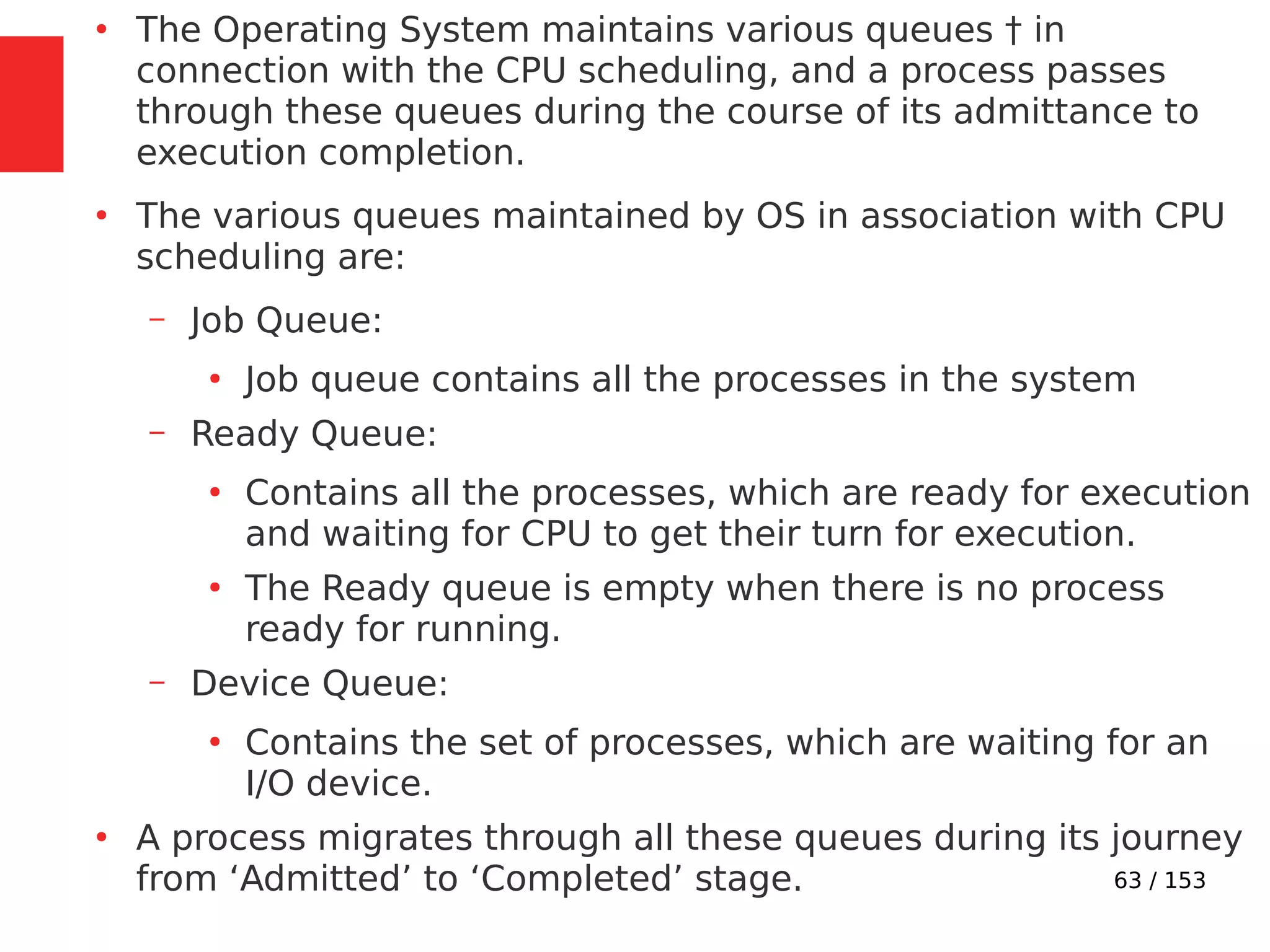
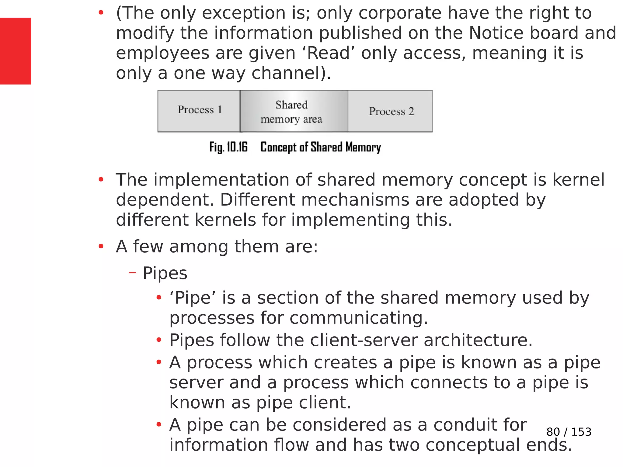
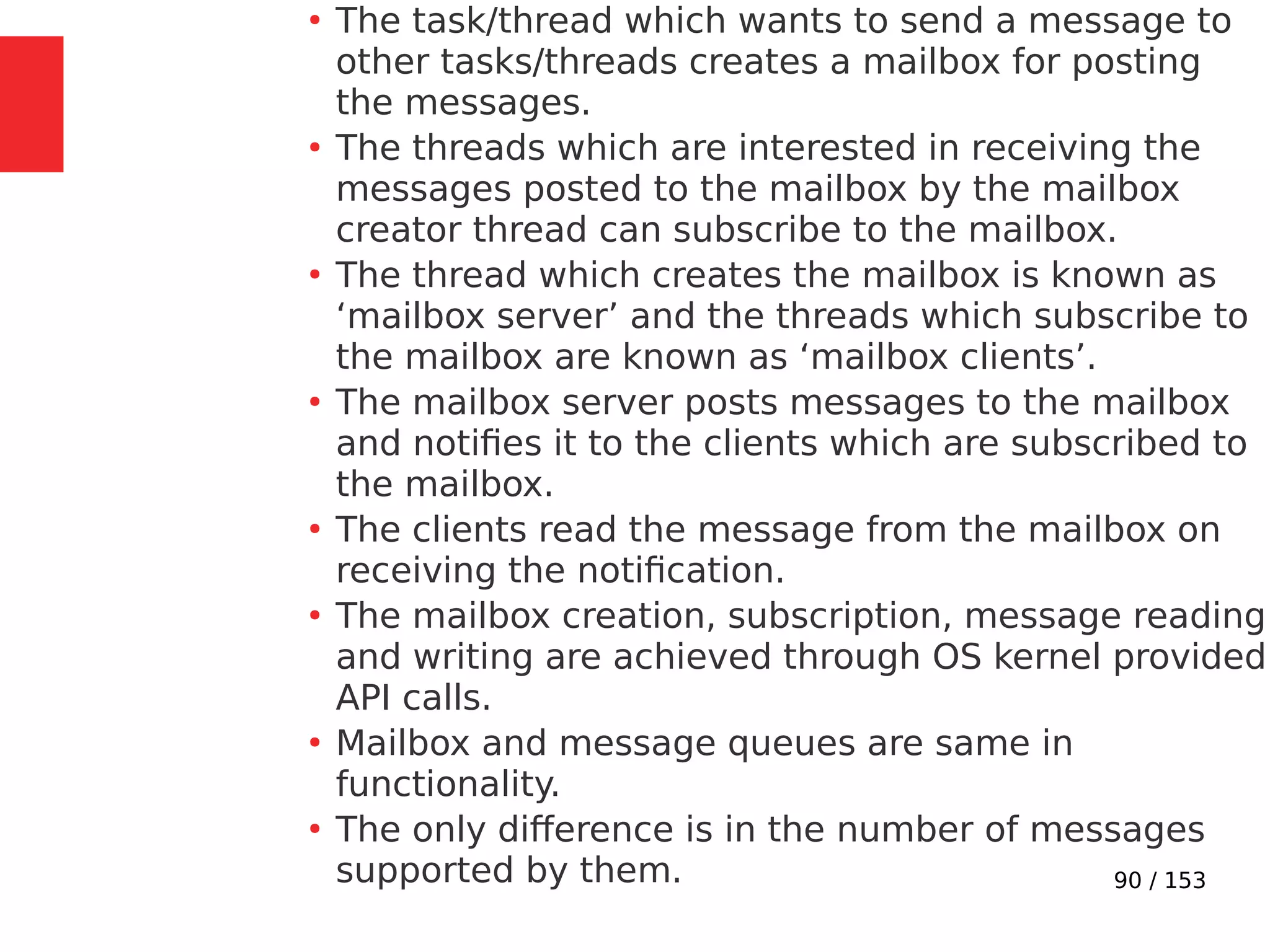
The document discusses the fundamentals of operating systems, including their roles in managing system resources, process management, memory management, file system handling, I/O management, and security. It distinguishes between general-purpose operating systems (GPOS) and real-time operating systems (RTOS), highlighting the deterministic behavior required in RTOS for time-critical tasks. Additionally, it covers kernel architecture, differentiating between monolithic and microkernel designs, and explains task control blocks and memory management techniques in the context of real-time operating environments.


![106 / 153
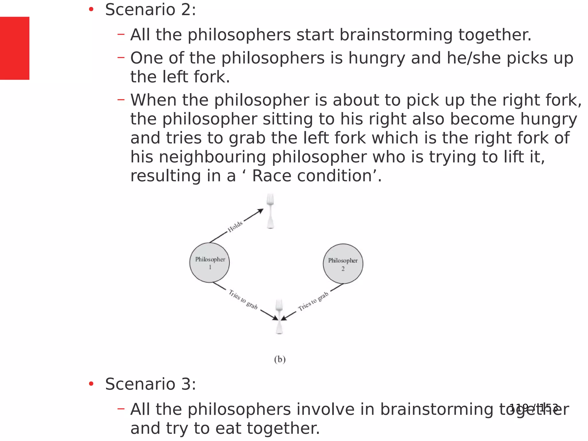
●
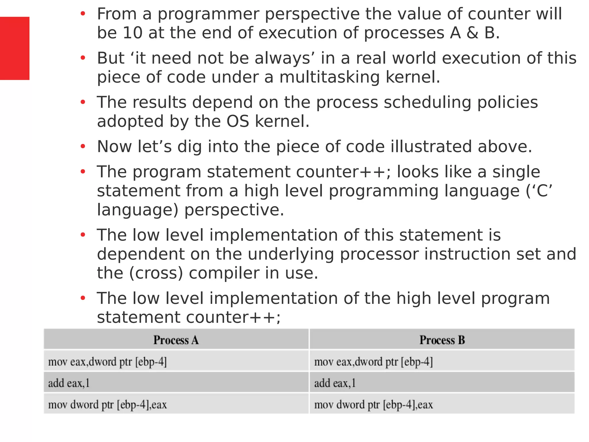
Imagine a situation where a process switching (context
switching) happens from Process A to Process B when
Process A is executing the counter++; statement.
●
Process A accomplishes the counter++; statement
through three different low level instructions.
●
Now imagine that the process switching happened at the
point where Process A executed the low level instruction,
‘mov eax,dword ptr [ebp-4]’ and is about to execute the
next instruction ‘add eax,1’.](https://image.slidesharecdn.com/module3-230505041442-f7fb499f/75/Real-Time-Embedded-System-Design-106-2048.jpg)