This document provides a comprehensive overview of centrifugal pumps, including their purpose, various types, and key considerations for selection such as capacity, differential pressure, and fluid characteristics. It details specific pump designs, materials, bearing types, lubrication requirements, and performance evaluations necessary for proper operation and efficiency. A focus is also placed on maintenance considerations and the factors influencing pump reliability and longevity.


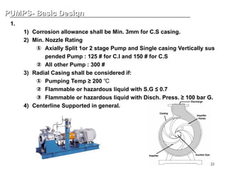
![24
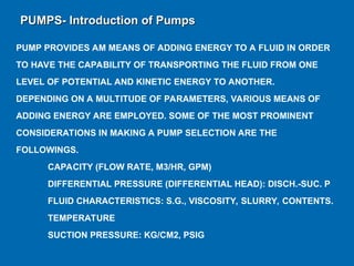
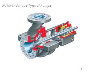
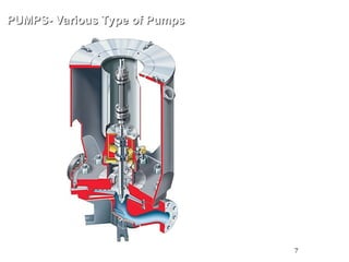
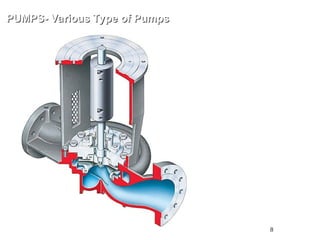
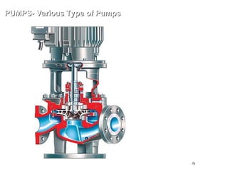
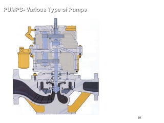
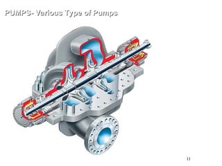
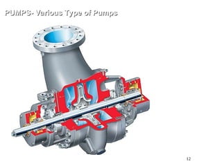
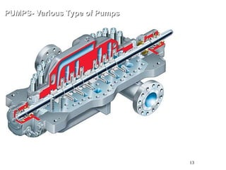
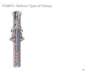
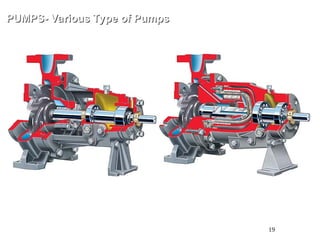
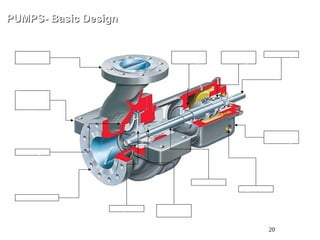
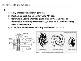
PUMPS- Basic Design
PUMPS- Basic Design
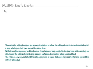
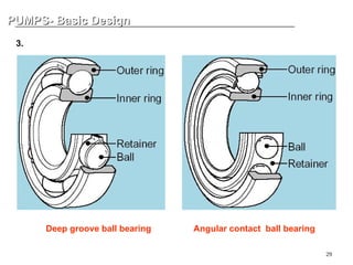
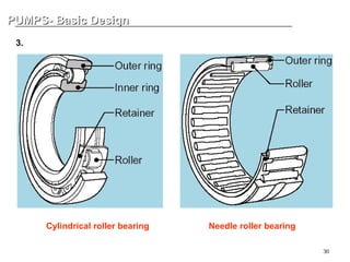
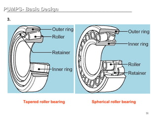
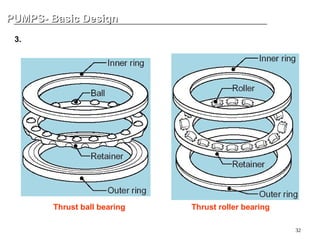
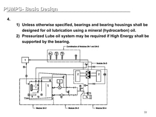
3. Bearing
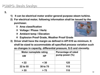
Condition Bearing type and arrangement
Radial and thrust bearing speed and life within limits for
rolling element bearings and Pump energy density
below limit
Rolling-element radial and thrust
Radial bearing speed or life outside limits for rolling-
element bearings and Thrust bearing speed and life
within limits And Pump energy density below limit
Hydrodynamic radial and rolling-element thrust
or
Hydrodynamic radial and thrust
Radial bearing speed or life outside limits for rolling-
element bearings and Thrust bearing speed and life
within limits And Pump energy density above limit
Hydrodynamic radial and thrust
Limits are as follows.
a) Rolling-element bearing speed: Factor, n.dm shall not exceed 500 000 where
dm is the mean bearing diameter [(d + D)/2)], expressed in millimetres;
n is the rotational speed, expressed in revolutions per minute.
b) Rolling-element bearing life: basic rating life, L10, in accordance with ISO 281, equivalent to at
least 25 000 h with continuous operation at rated conditions, and at least 16 000 h at maximum
radial and axial loads and rated speed.
c) Hydrodynamic radial and thrust bearings shall be used if the energy density [i.e. the product of
pump rated power, kW (hp), and rated speed, r/min] is 4,0 × 10⁶
kW/min (5,4 × 10⁶
hp/min) or
greater.](https://image.slidesharecdn.com/centrifugalpumptraining-241229091157-ed4cf175/85/Basic-Centrifugal-Pump-Training-presentation-24-320.jpg)