This document summarizes a presentation on quantum tunneling PUFs and their applications in security. The key points are:
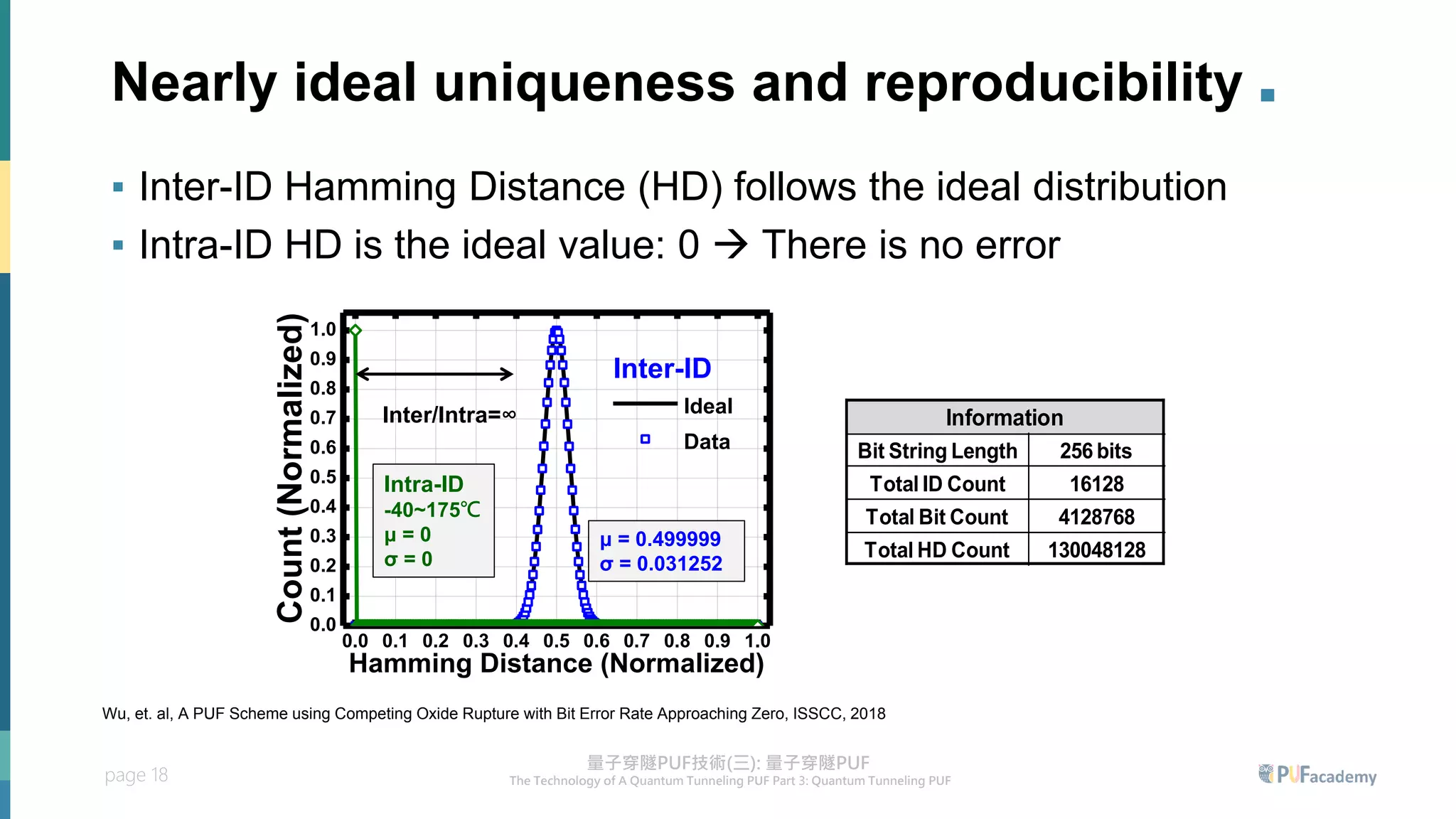
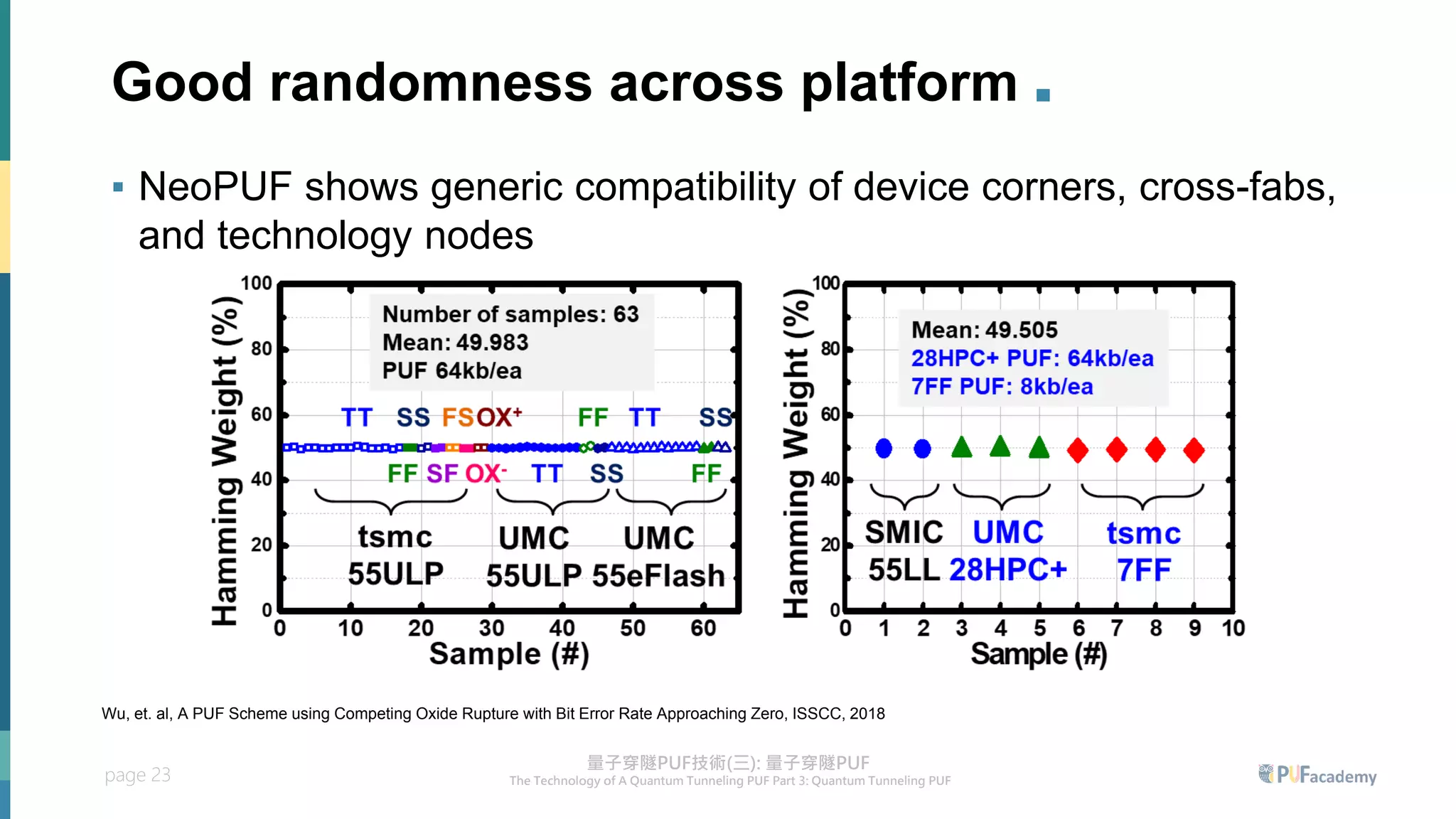
1. A quantum tunneling PUF is designed that generates bits based on the tunneling current of PUF cells, which provides near-ideal uniqueness and reproducibility across varying conditions.
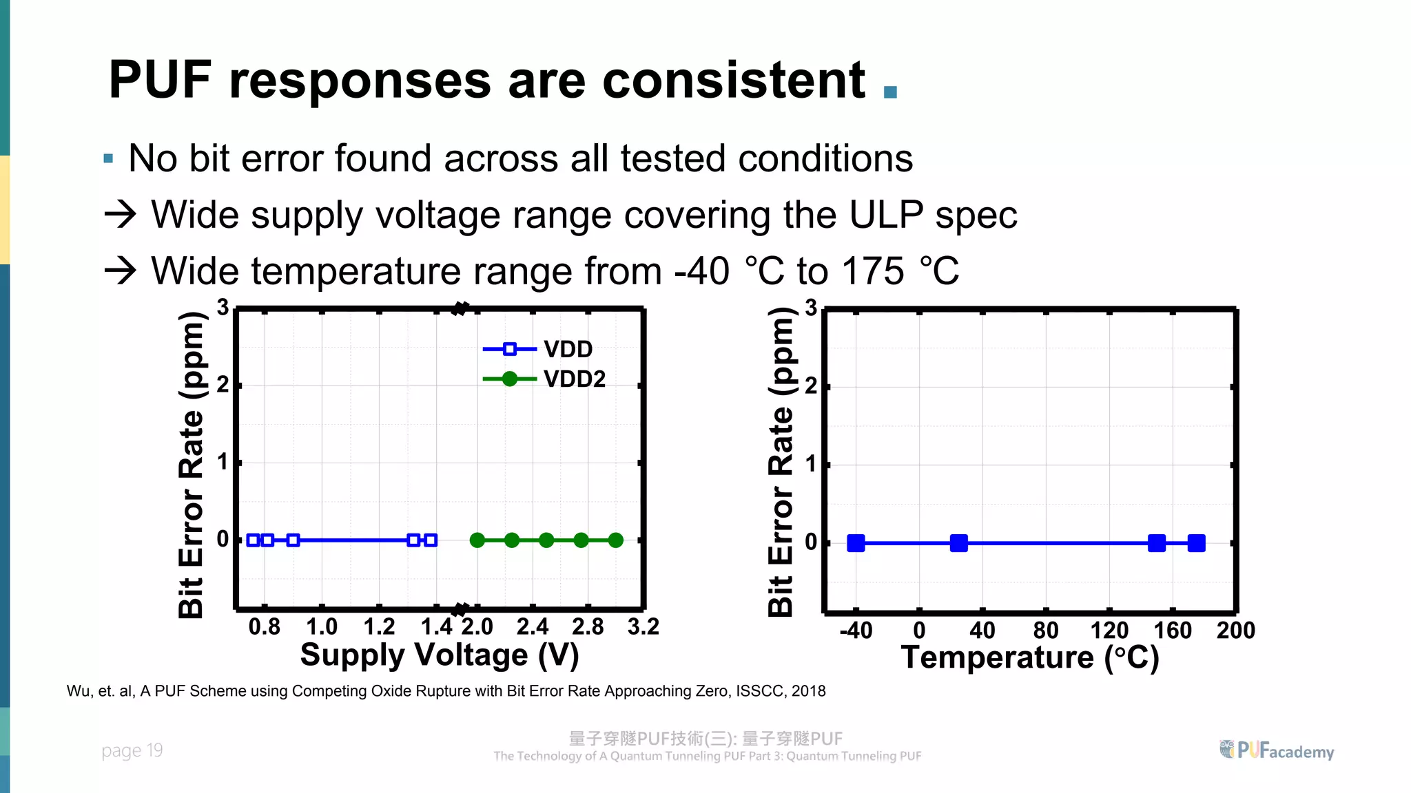
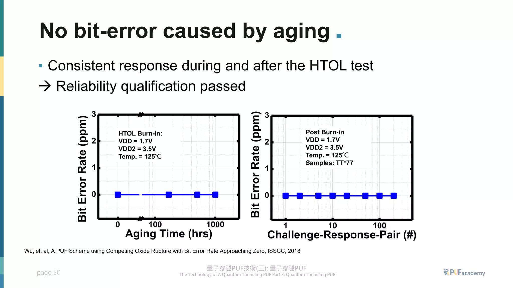
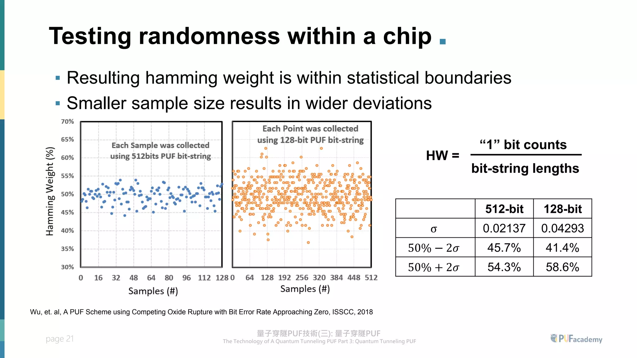
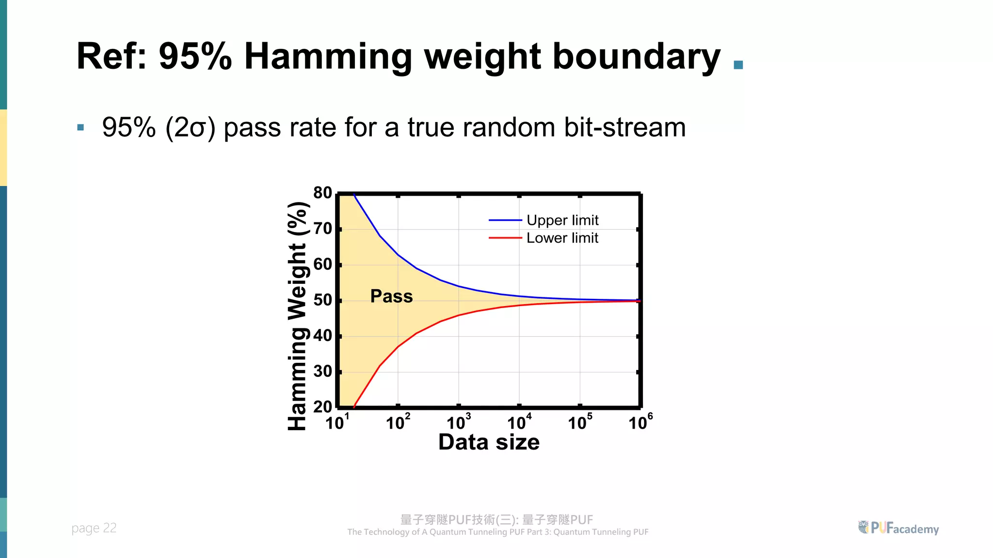
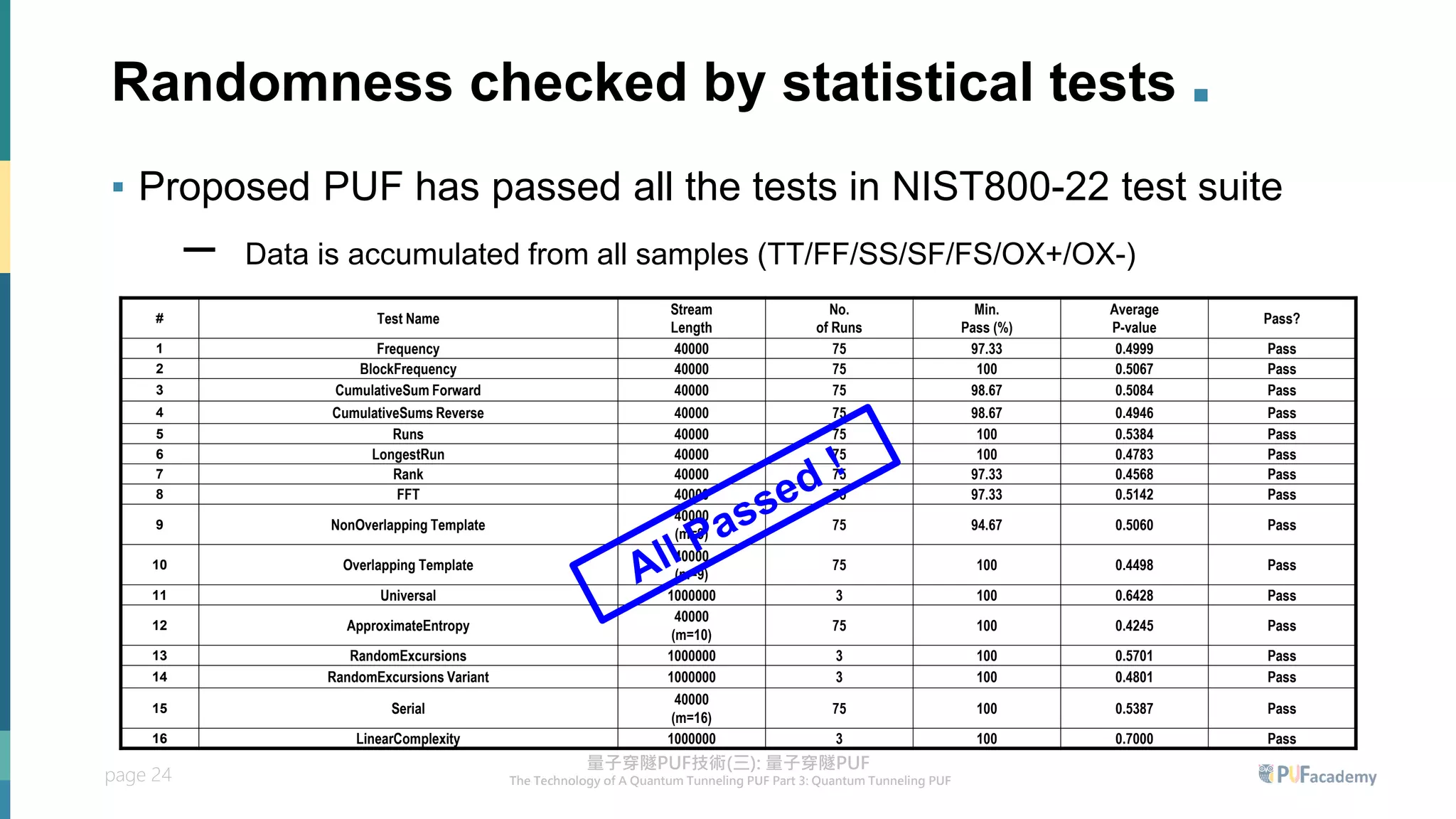
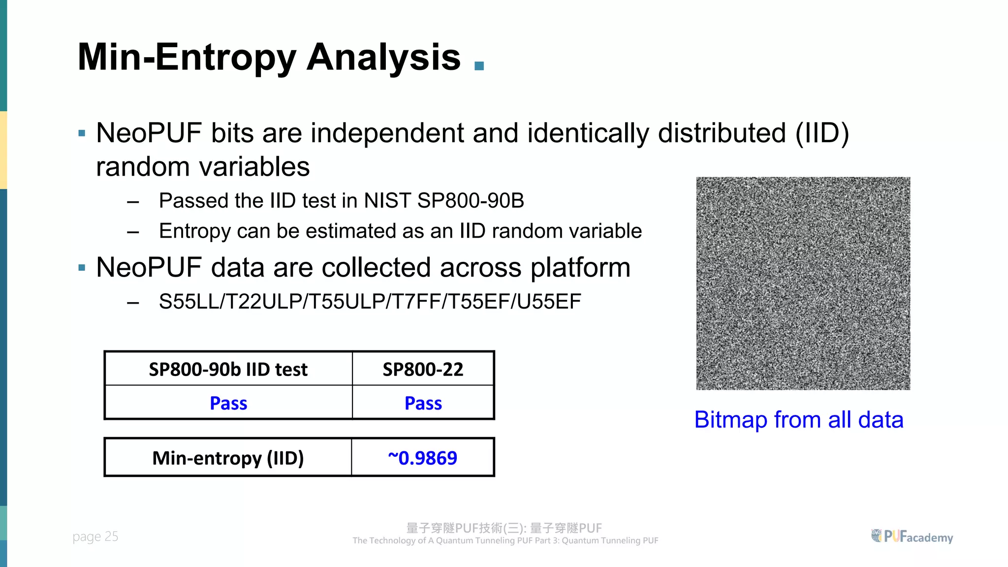
2. Experiment results on the quantum tunneling PUF show zero bit errors across wide voltage and temperature ranges as well as aging tests. Statistical tests also confirm the random behavior of its responses.
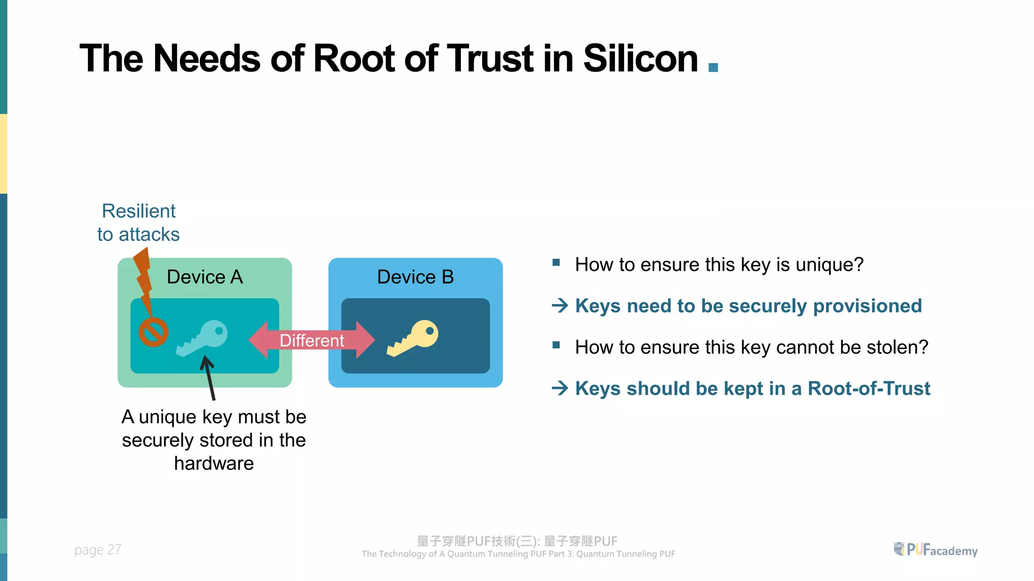
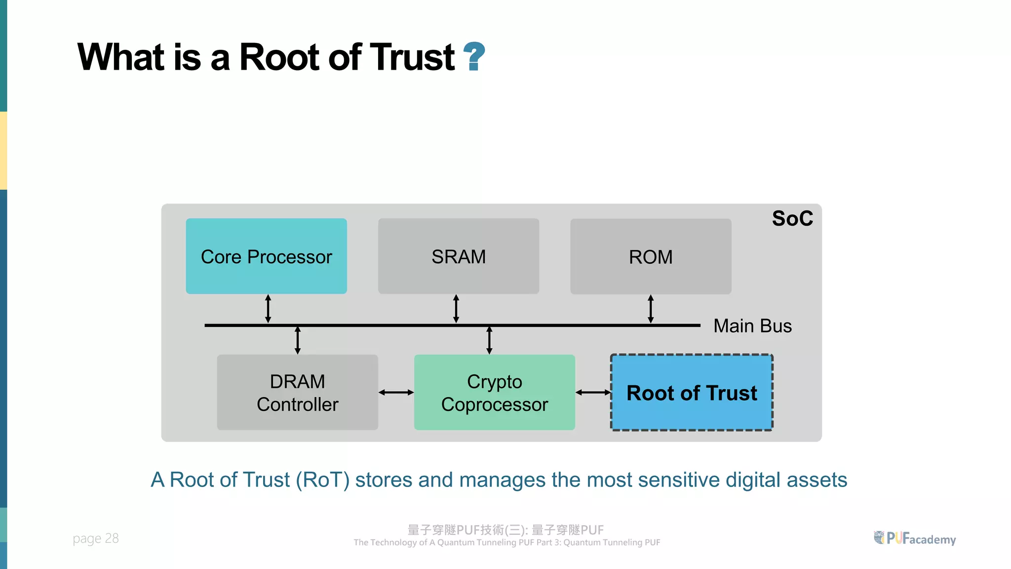
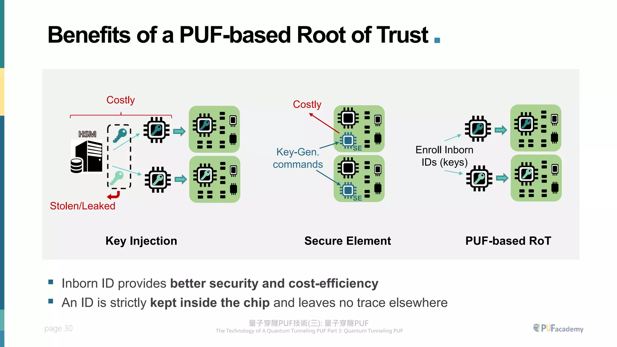
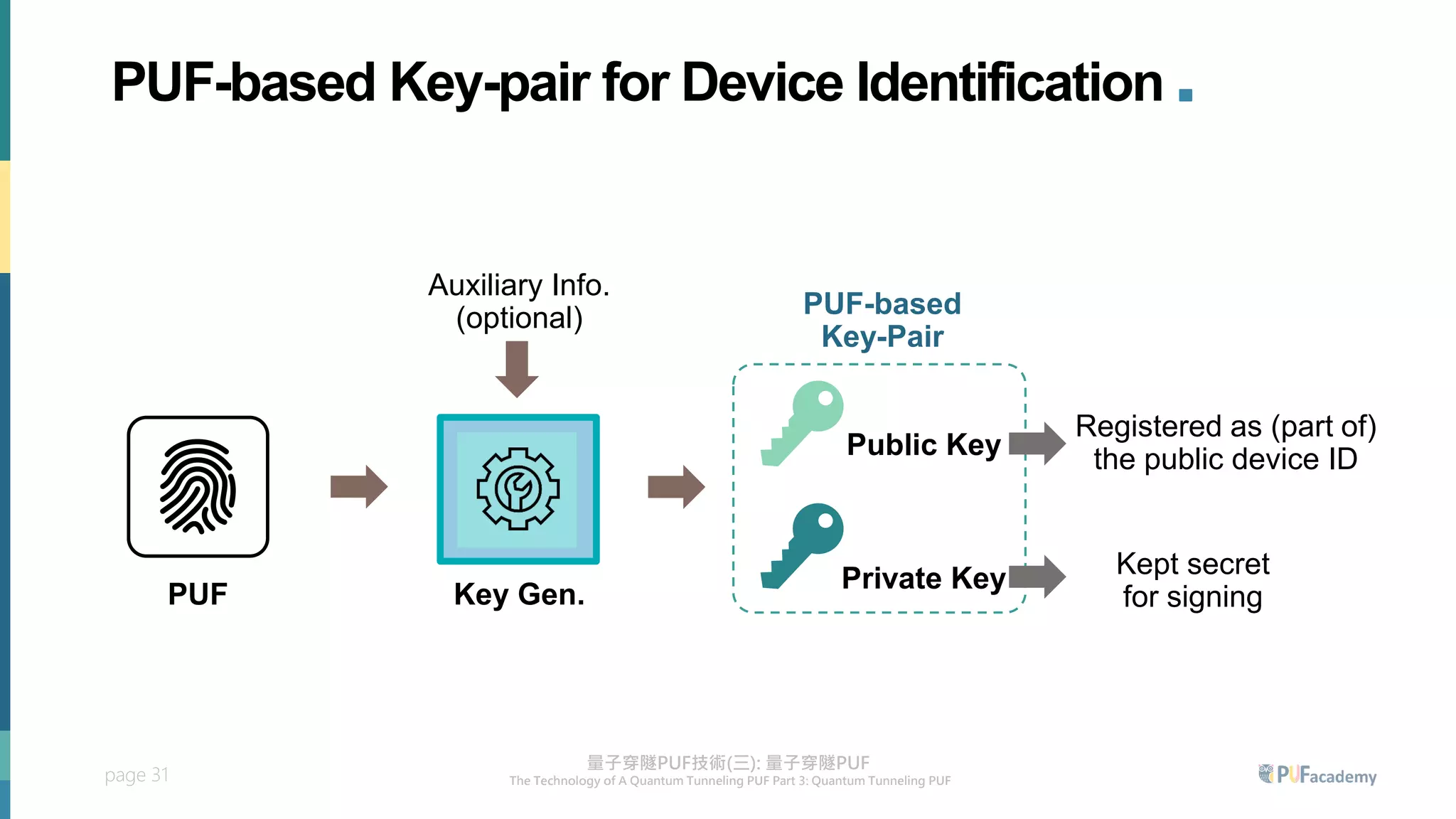
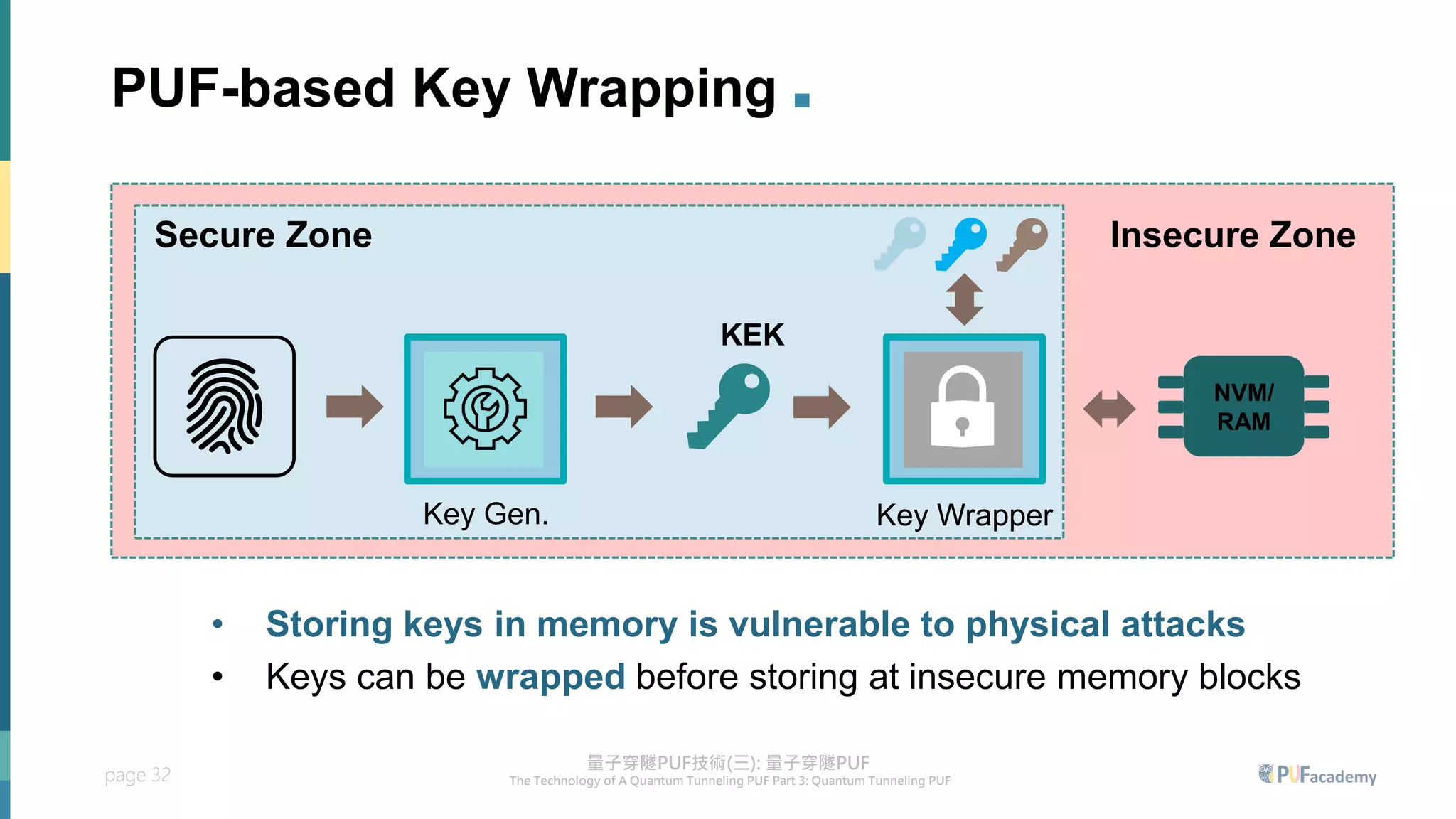
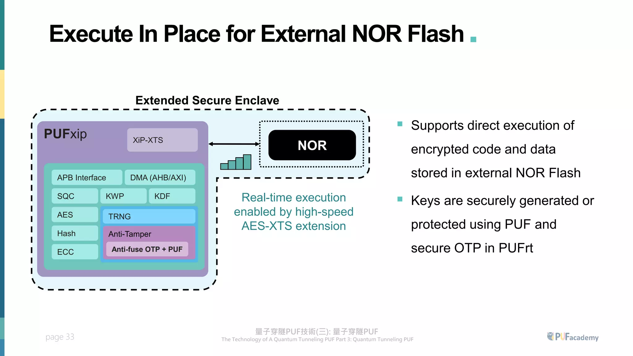
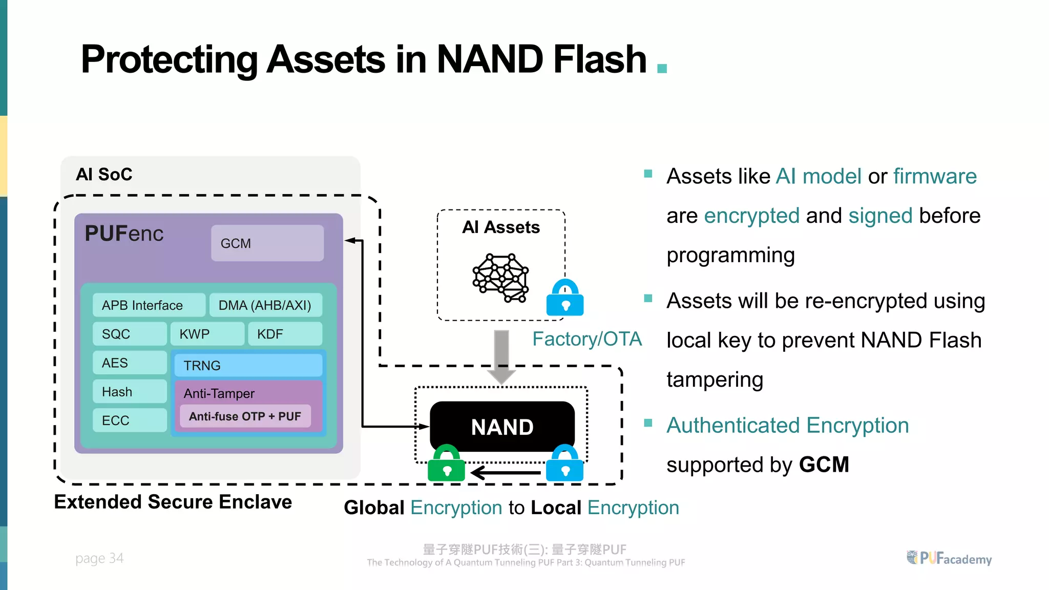
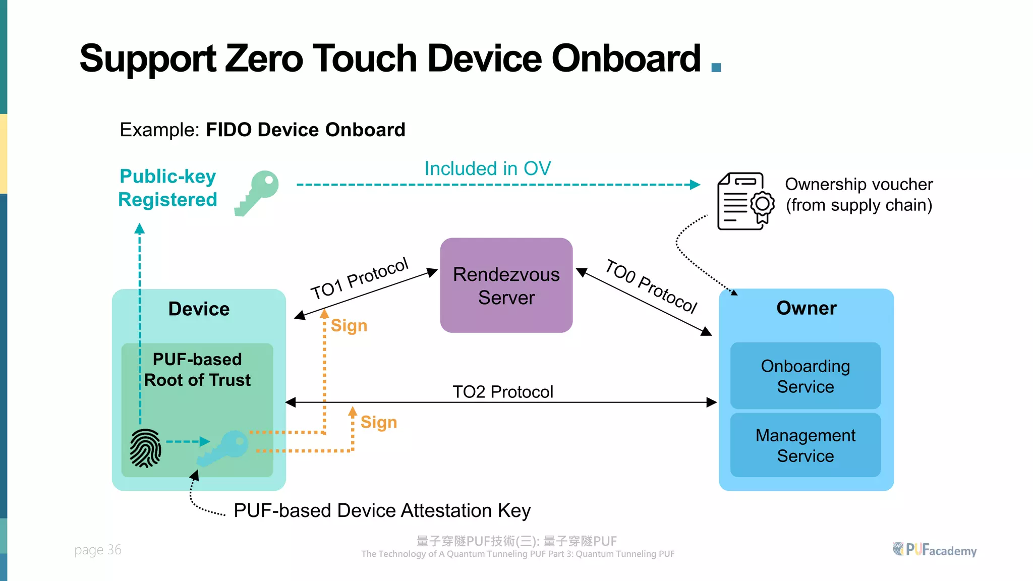
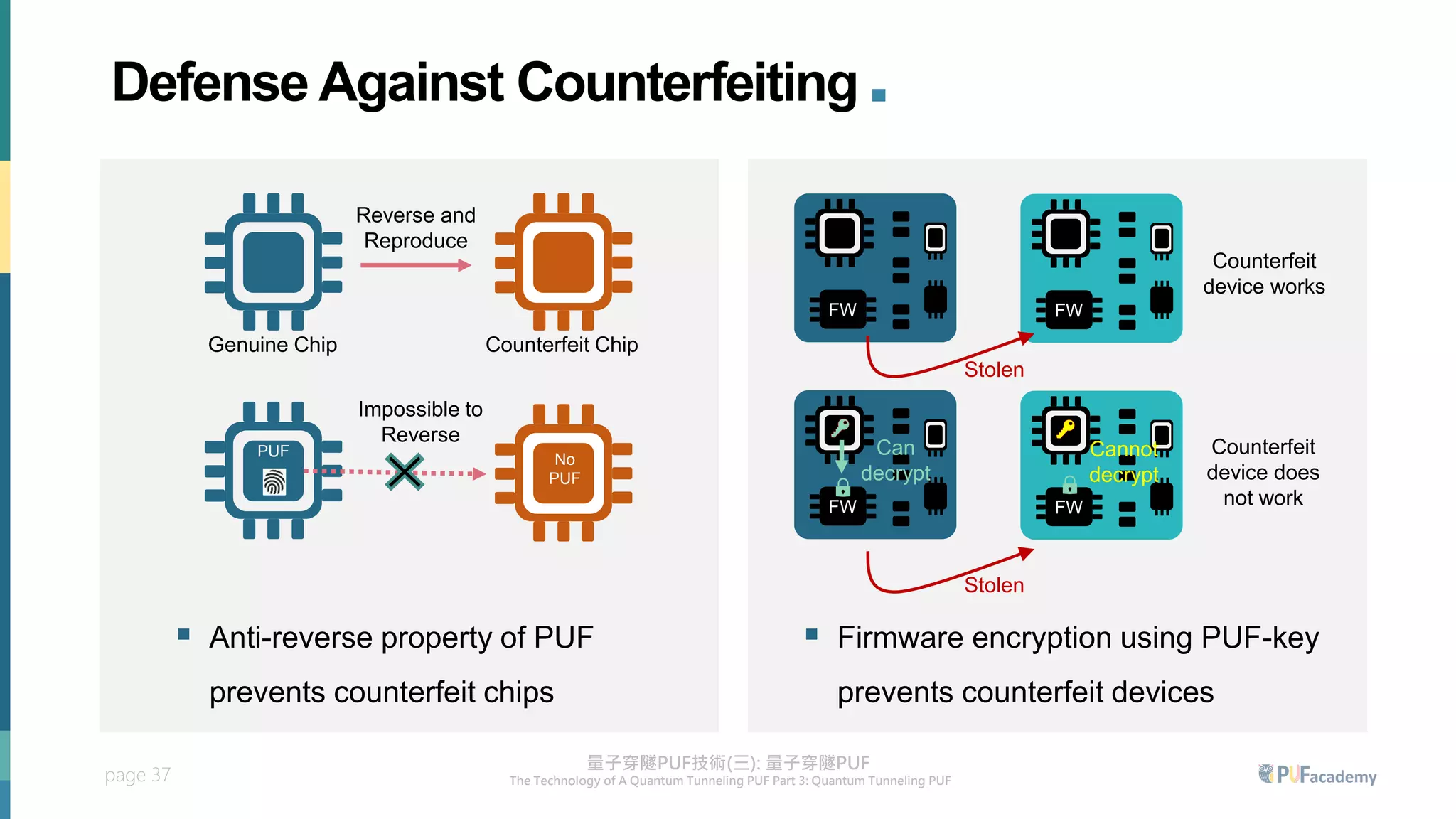
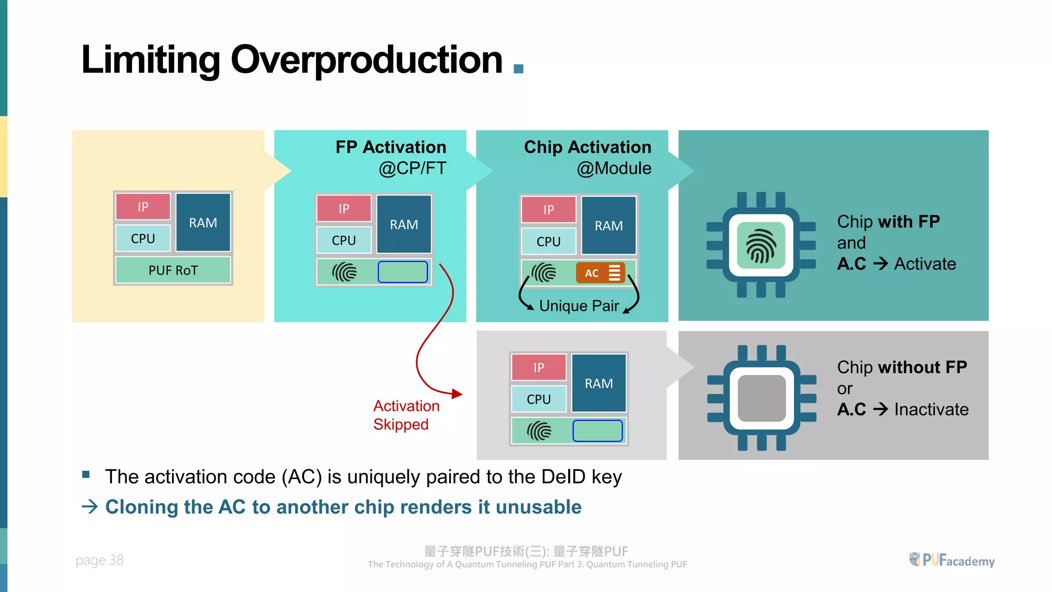
3. The quantum tunneling PUF can serve as an inborn hardware root of trust to securely generate and store keys. It enables various PUF-based security applications like device identification, encrypted storage, and prevention


![page 9
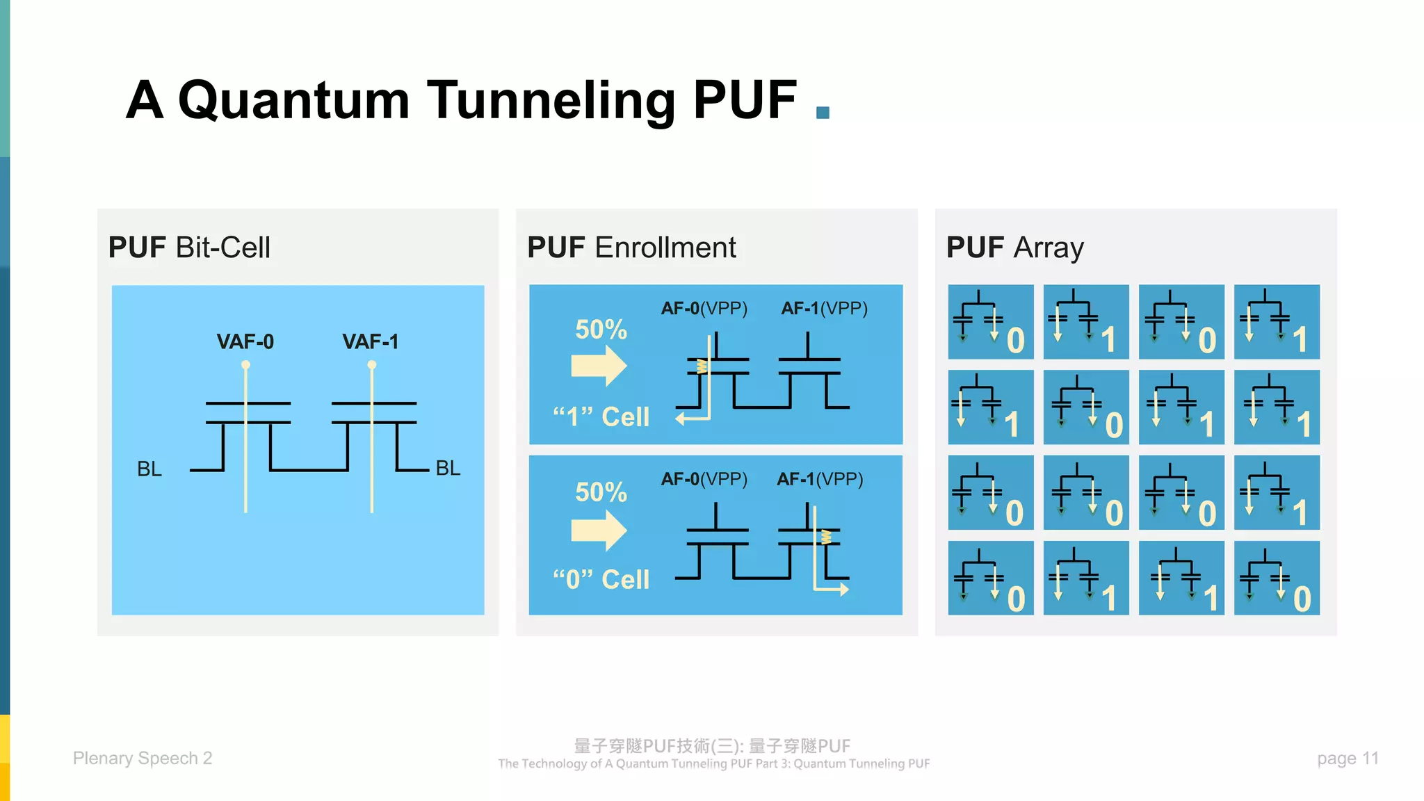
Quantum Tunneling PUFs .
“0” “1”
50% 50%
[Chuang, JSSC 2019]
[Wu, ISSCC 2018]
50% 50%
“0” “1”
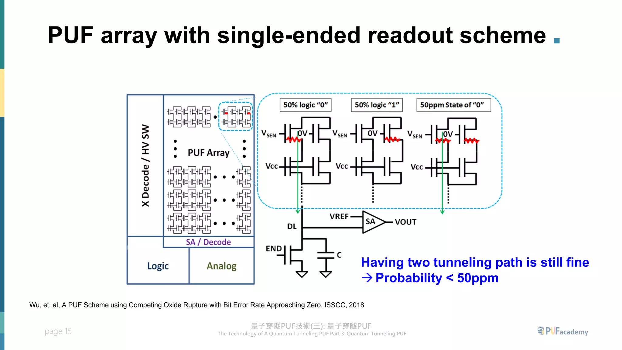
▪ Only one tunneling path will be generated in two of the NMOS transistors
▪ Reading out the tunneling current of PUF cells → deriving PUF bits](https://image.slidesharecdn.com/puflecture3-230606124336-437eca93/75/PUF_lecture3-pdf-9-2048.jpg)