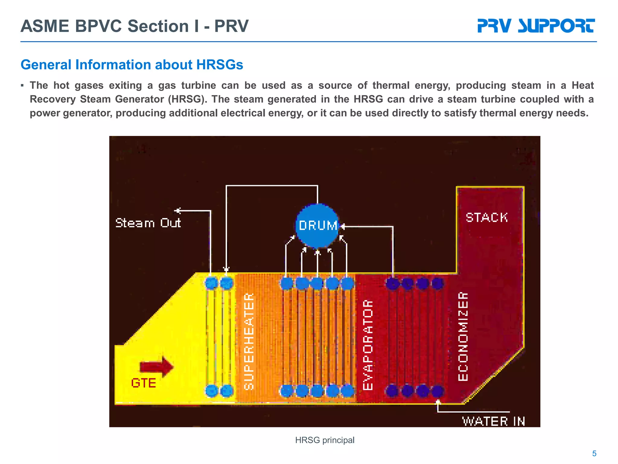
The document provides an overview of ASME B&PV Code Section I requirements for pressure relief valves (PRVs). It discusses the history and development of the code, typical boiler configurations that utilize PRVs, PRV performance requirements including set pressure, blowdown and flow coefficients, material selection standards, and applications for PRVs on boilers, heat recovery steam generators, and other vessels. It also summarizes key operating requirements for PRVs regarding overpressure, blowdown, and accumulation limits.
The document summarizes the use of a gas-lift hybrid system using both electrical submersible pumps (ESPs) and gas lift in offshore wells in Northwest Java. It provides background on the field and outlines the benefits of the hybrid system, including optimizing production rates and ensuring uninterrupted production. It presents an example of implementing the hybrid system on two wells when one ESP failed, allowing continued production. The hybrid system was found to prevent lost production and increase profits compared to conventional methods.
Camco injection-pressure-operated gas lift valves use nitrogen-charged bellows and a hydraulic dampening system to remain closed until overcoming the bellows pressure from injection gas. They are used for continuous or intermittent production through tubing or annular flow. Benefits include uniform operation, extended run life, versatility, and increased reliability and efficiency. Valves are available in 1-inch or 1.5-inch sizes with port options and integral reverse-flow check valves.
Ray Beebe has over 50 years of experience in power generation and condition monitoring of steam turbines. He discusses several case studies where condition monitoring helped identify issues in steam turbines. Condition monitoring techniques like vibration analysis, performance analysis of parameters like valve output, stage pressures and enthalpy drop efficiency can help detect problems like blade deposits or damage. The case studies show how condition monitoring helped detect issues and schedule repairs before further degradation occurred. Mr. Beebe emphasizes that condition monitoring data should be used to only open turbines for repair when there are clear technical and economic reasons to do so.
This document provides information on gas lift valve mechanics, including the three basic types of gas lift valves, how they operate, and the forces involved in opening and closing them. It discusses unloading valves, orifice valves, and how gas lift valves close in sequence from the bottom of the well upward. Diagrams show the components of different gas lift valve designs and the formulas used to calculate valve opening and closing pressures.
The document discusses various issues encountered with rod pump systems in Agiba oil fields and the remedial actions taken. It covers problems like gas interference, fluid pounding, scale deposition, sucker rod failures, sand production, stuck pumps, and tubing wear. Tests of techniques like gas anchors, variable slippage pumps, hollow sucker rods, and roller guides are summarized. Common troubleshooting indicators and techniques are also outlined, along with practices to avoid.
Bullheading is a common non-circulating method for killing live wells prior to workovers. It involves pumping kill fluid into the tubing to displace produced fluids back into the formation. A bullheading schedule is generated using formation pressure, desired overbalance, fracture pressure, tubing specifications, and pump data to safely control pumping pressures within the initial and final maximum pressures. The schedule provides checkpoints to monitor pumping pressure and volume throughout the operation. Special attention should be paid to any increases in casing pressure which could indicate downhole issues.
The document provides information about the boiler feed water pump system used in a power plant, including its purpose, components, technical specifications, maintenance procedures, and troubleshooting guidelines. The system consists of a booster pump and larger feed water pump coupled together and driven by a single electric motor. Key components are described in detail, such as the pumps, turbo coupling, motor, and balancing device. Periodic maintenance tasks and clearances are outlined. Common issues that may arise are identified along with recommended solutions.
This document discusses various artificial lift methods used to increase production from oil and gas wells as reservoir pressure declines. It describes the basic principles and components of common artificial lift techniques, including sucker rod pumps, gas lift, electrical submersible pumps, hydraulic jet pumping, plunger lift, and progressive cavity pumping. For each method, it provides information on advantages, limitations, and typical application ranges for operating parameters such as depth, production rate, temperature, and wellbore geometry. The document aims to provide an overview of different artificial lift options and considerations for selecting the appropriate production method.
This document provides specifications for horizontal and vertical fire-fighting pumps and packages that meet UNI EN 12845 and UNI EN 12259-12 standards. It includes performance ranges, dimensions, materials, and test procedures for horizontal split-case centrifugal pumps and vertical shaft turbine pumps. Installation diagrams and specifications are also provided for electric motor and diesel engine driven fire pump sets with controllers.
This document discusses well control equipment used in drilling operations. It describes blowout preventers (BOPs) which are used to close the well and control kicks before they become blowouts. There are different types of BOPs including annular preventers, ram preventers, and rotational preventers. Other important well control equipment includes an accumulator unit to operate BOPs hydraulically, inside BOPs, choke and kill lines, and a wellhead with casing heads to support tubulars and control fluid flow. Components should be function tested at least weekly to verify operations and actuation times should be recorded.
The document discusses different procedures for maintaining well control during workovers and completions when formation pressures change, including how to identify and respond to kicks, calculate proper mud weights, and kill wells under various pressure conditions. Key causes of kicks are identified as insufficient mud weight, improper hole fill-up when tripping pipe, swabbing effects when pulling pipe, and mud weight being reduced by gas cutting. Warning signs of kicks that should be monitored include increased flow rates, flow with pumps off, decreased pump pressures combined with increased stroke counts, improper hole fill-up, and changes in string weight.
Gas Lift Optimization and Troubleshooting Bailey LeRoux
This document provides an overview of gas-lift optimization and troubleshooting. It discusses identifying underperforming wells using metrics like the well performance factor and target injection differential. It then covers optimizing wells by adjusting injection gas rates, removing surface restrictions, redesigning the system, and adding secondary lift. Common inlet, outlet, and downhole problems are outlined along with tests and adjustments to address issues. Tuning the well for continuous flow is also described. Finally, tools for surface and subsurface data collection to aid in troubleshooting are listed.
This is a packaged clean steam generator ready for use after connection of utilities. The unit produces clean steam using a purified feedwater source and plant steam.
This document discusses the benefits of variable speed fire pump controllers compared to conventional controllers. Variable speed controllers can maintain a constant system pressure without the need for pressure reducing valves (PRVs) by adjusting the pump speed. This allows taller buildings to be designed without PRVs, saving significant costs. It also improves reliability by having redundant control circuits. While conventional controllers require PRVs for most floors in a 12-story building example, incurring high costs, a variable speed controller can maintain safe pressures on all floors without PRVs.
The presentation discuss about the operations, causes and remedies for the facing emergencies of steam Turbines. Specially for the 210MW LMW units. The emergencies can be created on simulator and studied on the simulator ACCORDINGLY.
Sucker rod pumping short course!!! ~downhole diagnosticenLightNme888
Six-page Petroleum Engineering info-graphic detailing Sucker Rod Pumping of Oil Wells and how to effectively design, operate, and optimize the well's producing efficiency. This is an amazing reference guide for anyone involved with Beam Lift as a means of Artificial Lift!!
www.downholediagnostic.com
The document provides instructions for erecting pressure parts for a conventional 250 MW boiler. It outlines the sequence and key steps, which include erecting 3850 MT of boiler structure first, lifting the boiler drum using strand jacks, then erecting the furnace and second pass from top to bottom. Seal welding and insulation are also covered. The overall goal is to assemble the 5600 MT of pressure parts components within tolerances to achieve the desired performance during operation.
The leading manufacturer in High pressure pump
- The specialized company in Air Gas Booster, Air Liquid pump, metering pump, the pressure testing machine, etc.
Insertion turbine flow meters measure flow of liquid, gas, and
steam by detecting the frequency of rotation of the turbine blades. The frequency of turbine rotation is directly proportional to the flow velocity. Insertion turbine flow meters measure flow by detecting the local velocity within the pipe. The fluid velocity is combined with other parameters to calculate the average pipe velocity and volumetric flow rate.
This document provides an overview of basic well control procedures including:
- Kick detection and control methods like primary prevention and secondary detection and control
- Shut-in procedures such as hard, soft, and specialized shut-ins
- Well kill procedures including calculating initial and final circulating pressures, the wait-and-weight/engineer's method, and providing an example pump schedule.
It describes the key objectives and considerations for safely controlling a well when kicks occur and bringing the well pressure to a controlled state.
This document discusses definitions and requirements related to fire pumps according to NFPA 20. It defines key terms like "authority having jurisdiction" and "approved" and discusses requirements for water supply sources, pump types, installation, and testing. Specific topics covered include acceptable suction lift for centrifugal pumps, necessary water supply flow and pressure, requirements for packaged and field-erected pump houses, and guidelines for piping, valves, and other pump components.
The document provides guidelines for erecting headers in boiler pressure parts. It describes preparing the supporting structures by checking dimensions according to structural drawings and pressure parts drawings. Headers must be erected at proper locations and orientations indicated by mark numbers on drawings and components. Temporary attachments used for erection must be removed after completion. Clearance between headers and supports must be checked to allow for thermal expansion.
The document provides technical specifications for erecting a 500 MW steam turbine from KWU design, including:
- It is a three cylinder reheat condensing turbine with a single flow HP turbine, double flow IP turbine, and double flow LP turbine.
- It has main stop and control valves, reheat stop and control valves, and extraction swing check valves.
- The rated speed is 50.0 revolutions per second and the maximum under valve wide open condition is 524.2 MW.
Kicks occur when formation pressures exceed the hydrostatic pressure of the drilling mud, allowing formation fluids to enter the wellbore. This can lead to a blowout if not controlled. Common causes of kicks include failing to keep the hole full, using insufficient mud density, swabbing during trips, lost circulation, and incorrect fill-up. Detecting kicks involves monitoring for increases in pit volume, return flow, drilling break, circulating pressure, shows of oil/gas/water, and hook load. Well control equipment like blowout preventers, choke manifolds, and degassers are used to safely circulate out kicks without allowing a blowout. Key parameters for well monitoring include rate of penetration, hook load, RPM, rot
Fire pumps are pumps certified to NFPA 20 standards that provide reliable water supply for fire protection systems. They enhance water pressure and cannot create water flow. Fire pumps require regular inspection and testing to verify they are operating properly and free of issues. Weekly inspections include checking components like valves, gauges, fuel levels, and batteries, while weekly tests involve starting the pump without water flow to check for abnormal noises, vibrations, or overheating that could indicate maintenance is needed.
This document discusses NFPA20, which establishes standards for stationary fire pumps. It covers the purpose of fire pumps in supplying adequate water for fire protection systems. Fire pumps must be listed by authorities and sized according to NFPA standards. The document discusses various types of fire pumps and their applications. It also covers requirements for accessories like gauges, valves, and relief valves. Diesel and electric fire pump controllers are addressed, including their functions, starting methods, and alarm capabilities. Pump maintenance and testing procedures are also summarized.
The document describes the key components and operating parameters of high pressure ammonia feed pumps (P-1). P-1 pumps ammonia at high pressure from 20-240 kg/cm2. It consists of reciprocating plungers, packing seals, lube oil systems, and driving components. Critical parameters include plunger speed, discharge pressure, seal water pressure, and lube oil pressure which are monitored to protect the pump. Detailed startup, operation, and shutdown procedures are outlined to safely charge and depressurize the pump.
Learn how we design these components for high temperature, high pressure, and/or corrosive environments. Discover the different materials used based on a variety of applications. View some of the very unique and intricate Sweco custom designs, and corresponding technical drawings. Sweco designs and manufactures Pressure Vessels and Tanks, Pig Launchers and Receivers, Duct Work, Transition Pieces, Bellmouth Reducers, Spectacle and Line Blinds, Air Intake Stacks and Dampers, Conical Strainers, Instrument Stands and other custom fabricated products.
This document provides information about the 660MW turbo-generator and its associated systems for Stage-I of the Sipat Super Thermal Project. It summarizes key details about the steam turbine, its auxiliaries and rated operating conditions. The steam turbine is a K-660-247 model with 59 stages manufactured by LMZ. It operates at rated conditions of 660MW with steam pressure and temperature of 247KSC and 537°C respectively at the high pressure inlet. The document also outlines the turbine governing, lube oil, seal steam and control fluid systems along with specifications for materials, protections and auxiliaries.
This document discusses fugitive emissions from gland packings and provides an overview of various testing standards used to measure fugitive emissions. It summarizes:
- Fugitive emissions are unintended gas releases from industrial equipment that contribute to air pollution. Over 83% come from pumps, valves, flanges, and compressors.
- API 622 and API 624 are standards for testing valve packing materials and valves equipped with graphite packing. API 622 specifies parameters for temperature, pressure, cycles and corrosion resistance. API 624 tests actual valves.
- API 641 is a more complex standard for testing quarter-turn valves, with parameters dependent on valve design, temperature and pressure ratings. It allows for
This industrial training report summarizes the process for manufacturing generating transformers at BHEL Bhopal. It discusses the key steps which include design and drawing, core building by stacking laminated silicon steel sheets, winding manufacturing using horizontal and vertical winding machines, coil assembling, power assembly by mounting the core and coils, case fitting to connect accessories like bushings and radiators, vapor phase drying to remove moisture, testing including routine and type tests, and final dispatch after successful testing. The report provides details on the types of materials, winding configurations, and tests used at each stage of manufacturing large power transformers.
The stress analysis basis used in the ASME Code to analyze the nozzle reinforcement is called Beams on
Elastic Foundation (Hetenyi, 1946). This method determines the effectiveness of the material close to the
opening for carrying loads. Reinforcement limits are developed parallel and perpendicular to the shell surface
near the opening. Although the method is a simplified application of the elastic foundation theory, experience
has shown that it does a good job.
Values from two equations are used to set the reinforcement limits measured along the vessel wall surface.
The greater value sets the horizontal limit for that opening. The first value is equal to d, and the second
value is equal to 0.5d + t + tn as shown in Fig. 5.2. The relationship of the nozzle wall thickness
pressure vessel details for design and it componentsdhaneshmech1
The document discusses pressure vessel design according to the ASME Boiler and Pressure Vessel Code. It covers topics such as vessel shapes, orientations, closures, joints, nozzles, supports, and internals. The key points are:
- Pressure vessels are usually cylindrical in shape for uniform flow and easier distribution of fluids. Spheres require the least material but are not widely used.
- Vertical orientation is most common for smaller footprint and easier distribution. Horizontal vessels promote phase separation.
- Welded joints are preferred but gasketed joints allow for frequent opening. Nozzles are needed for feeds, products, utilities and instrumentation.
- Reinforcement is required around nozzles to strengthen the shell
660 mw turbo generator & its auxiliariesAshvani Shukla
This document provides an overview of the 660MW turbo-generator, its auxiliaries, and associated systems. Some key points:
- The turbo-generator has 26 concrete columns supporting its deck. The turbine hall has 3 rows of columns and 2 bays of different widths.
- The turbine is rated for 660MW and has 59 stages total across its high pressure, intermediate pressure, and low pressure sections.
- Auxiliary systems include lube oil, seal steam, control fluid, and protection systems. Materials of construction include various steel and alloy compositions.
- Comprehensive details are given on system parameters, components, piping, instrumentation, and operations across the main turbine and auxiliary systems
Pressure reducing stations (PRS) is the arrangement of certain valves which is used to provide desired steam pressure at user’s end. Steam coming from the Boiler, through the steam line, enters the PRS at a higher pressure and leaves the PRS at reduced (specified) pressure, in this the flow of the steam remains constant. Like Steam Boiler, PRS is also pressure equipment.
This document provides an overview of API 6A, which establishes specifications for wellhead and Christmas tree equipment. It covers the scope of equipment covered, service conditions, material classes, pressure and temperature ratings, quality control requirements, and testing procedures. Equipment manufactured according to API 6A has undergone audits and testing to ensure it can withstand downhole conditions in the oil and gas industry.
This document discusses control valves used in thermal power plants. It covers topics such as control valve sizing, construction, types including top-guided, cage-guided and double-seated valves. It also discusses trim, materials, cavitation prevention, leakage classification, fail-safe design, noise control, testing and standards. The document aims to provide an overview of key considerations for control valves used in critical applications in thermal power generation.
This document provides an overview of progressive cavity pump (PCP) systems. It describes the key components of PCP systems including surface equipment like drive heads and downhole equipment like rotors and stators. It explains how PCP systems are configured and operated, highlighting safety systems, operating parameters, and advantages for applications like dewatering wells. Vendors for major PCP components are also listed.
This document provides details about the 660MW turbo-generator and its associated systems at Stage I of the Sipat Super Thermal Project. It discusses the key specifications and parameters of the steam turbine, generator, governing system, lube oil system, seal steam system, materials of construction, protection systems, and control fluid system. The summary includes the turbine's manufacturer, rated load, steam conditions, number of stages, generator specifications, operating parameters, and materials used in major components.
Husk based power plant 6 t 32 kg fbc with single stage turbine for finance,...Radha Krishna Sahoo
This document provides an offer from Industrial Boilers Ltd for a high pressure husk fired fluidized bed combustion boiler and back pressure steam turbine system for a rice mill. It includes design parameters for the 6000 kg/hr boiler such as a steam pressure of 32 kg/cm2. It also lists the scope of supply for the boiler and its components as well as exclusions such as civil works and insulation. Annexures provide further details on the boiler, turbine, commercial offer, and terms and conditions.
Regulating Valves are available in two different versions – MREG-A and MREG-B designed for regulation purposes in liquid and expansion lines.MREG-A and MREG-B are angleway and straightway hand regulating valves, which act as normal stop valves in closed position.
Similar to Prvs 2. asme section i fired vessel rev4 (20)
Prvs 4b. sizing - fluid characteristics at discharge conditionsDavid Alexandre
This document defines key terms related to PRV sizing and discharge conditions, including critical point, supercritical fluid, sub-cooled liquid, saturated fluid, and non-condensable gas. It also summarizes alternative sizing methods from API STD 520, including equations for homogeneous fluids and two-phase liquid/vapor relief scenarios. Appendix C of API STD 520 provides sizing techniques for systems where the fluid enters the PRV already as a two-phase mixture or flashes into a two-phase mixture during depressurization.
Build the Next Generation of Apps with the Einstein 1 Platform.
Rejoignez Philippe Ozil pour une session de workshops qui vous guidera à travers les détails de la plateforme Einstein 1, l'importance des données pour la création d'applications d'intelligence artificielle et les différents outils et technologies que Salesforce propose pour vous apporter tous les bénéfices de l'IA.
Electric vehicle and photovoltaic advanced roles in enhancing the financial p...IJECEIAES
Climate change's impact on the planet forced the United Nations and governments to promote green energies and electric transportation. The deployments of photovoltaic (PV) and electric vehicle (EV) systems gained stronger momentum due to their numerous advantages over fossil fuel types. The advantages go beyond sustainability to reach financial support and stability. The work in this paper introduces the hybrid system between PV and EV to support industrial and commercial plants. This paper covers the theoretical framework of the proposed hybrid system including the required equation to complete the cost analysis when PV and EV are present. In addition, the proposed design diagram which sets the priorities and requirements of the system is presented. The proposed approach allows setup to advance their power stability, especially during power outages. The presented information supports researchers and plant owners to complete the necessary analysis while promoting the deployment of clean energy. The result of a case study that represents a dairy milk farmer supports the theoretical works and highlights its advanced benefits to existing plants. The short return on investment of the proposed approach supports the paper's novelty approach for the sustainable electrical system. In addition, the proposed system allows for an isolated power setup without the need for a transmission line which enhances the safety of the electrical network
Applications of artificial Intelligence in Mechanical Engineering.pdfAtif Razi
Historically, mechanical engineering has relied heavily on human expertise and empirical methods to solve complex problems. With the introduction of computer-aided design (CAD) and finite element analysis (FEA), the field took its first steps towards digitization. These tools allowed engineers to simulate and analyze mechanical systems with greater accuracy and efficiency. However, the sheer volume of data generated by modern engineering systems and the increasing complexity of these systems have necessitated more advanced analytical tools, paving the way for AI.
AI offers the capability to process vast amounts of data, identify patterns, and make predictions with a level of speed and accuracy unattainable by traditional methods. This has profound implications for mechanical engineering, enabling more efficient design processes, predictive maintenance strategies, and optimized manufacturing operations. AI-driven tools can learn from historical data, adapt to new information, and continuously improve their performance, making them invaluable in tackling the multifaceted challenges of modern mechanical engineering.
VARIABLE FREQUENCY DRIVE. VFDs are widely used in industrial applications for...PIMR BHOPAL
Variable frequency drive .A Variable Frequency Drive (VFD) is an electronic device used to control the speed and torque of an electric motor by varying the frequency and voltage of its power supply. VFDs are widely used in industrial applications for motor control, providing significant energy savings and precise motor operation.
Rainfall intensity duration frequency curve statistical analysis and modeling...bijceesjournal
Using data from 41 years in Patna’ India’ the study’s goal is to analyze the trends of how often it rains on a weekly, seasonal, and annual basis (1981−2020). First, utilizing the intensity-duration-frequency (IDF) curve and the relationship by statistically analyzing rainfall’ the historical rainfall data set for Patna’ India’ during a 41 year period (1981−2020), was evaluated for its quality. Changes in the hydrologic cycle as a result of increased greenhouse gas emissions are expected to induce variations in the intensity, length, and frequency of precipitation events. One strategy to lessen vulnerability is to quantify probable changes and adapt to them. Techniques such as log-normal, normal, and Gumbel are used (EV-I). Distributions were created with durations of 1, 2, 3, 6, and 24 h and return times of 2, 5, 10, 25, and 100 years. There were also mathematical correlations discovered between rainfall and recurrence interval.
Findings: Based on findings, the Gumbel approach produced the highest intensity values, whereas the other approaches produced values that were close to each other. The data indicates that 461.9 mm of rain fell during the monsoon season’s 301st week. However, it was found that the 29th week had the greatest average rainfall, 92.6 mm. With 952.6 mm on average, the monsoon season saw the highest rainfall. Calculations revealed that the yearly rainfall averaged 1171.1 mm. Using Weibull’s method, the study was subsequently expanded to examine rainfall distribution at different recurrence intervals of 2, 5, 10, and 25 years. Rainfall and recurrence interval mathematical correlations were also developed. Further regression analysis revealed that short wave irrigation, wind direction, wind speed, pressure, relative humidity, and temperature all had a substantial influence on rainfall.
Originality and value: The results of the rainfall IDF curves can provide useful information to policymakers in making appropriate decisions in managing and minimizing floods in the study area.
Digital Twins Computer Networking Paper Presentation.pptxaryanpankaj78
A Digital Twin in computer networking is a virtual representation of a physical network, used to simulate, analyze, and optimize network performance and reliability. It leverages real-time data to enhance network management, predict issues, and improve decision-making processes.
Embedded machine learning-based road conditions and driving behavior monitoringIJECEIAES
Car accident rates have increased in recent years, resulting in losses in human lives, properties, and other financial costs. An embedded machine learning-based system is developed to address this critical issue. The system can monitor road conditions, detect driving patterns, and identify aggressive driving behaviors. The system is based on neural networks trained on a comprehensive dataset of driving events, driving styles, and road conditions. The system effectively detects potential risks and helps mitigate the frequency and impact of accidents. The primary goal is to ensure the safety of drivers and vehicles. Collecting data involved gathering information on three key road events: normal street and normal drive, speed bumps, circular yellow speed bumps, and three aggressive driving actions: sudden start, sudden stop, and sudden entry. The gathered data is processed and analyzed using a machine learning system designed for limited power and memory devices. The developed system resulted in 91.9% accuracy, 93.6% precision, and 92% recall. The achieved inference time on an Arduino Nano 33 BLE Sense with a 32-bit CPU running at 64 MHz is 34 ms and requires 2.6 kB peak RAM and 139.9 kB program flash memory, making it suitable for resource-constrained embedded systems.
AI for Legal Research with applications, toolsmahaffeycheryld
AI applications in legal research include rapid document analysis, case law review, and statute interpretation. AI-powered tools can sift through vast legal databases to find relevant precedents and citations, enhancing research accuracy and speed. They assist in legal writing by drafting and proofreading documents. Predictive analytics help foresee case outcomes based on historical data, aiding in strategic decision-making. AI also automates routine tasks like contract review and due diligence, freeing up lawyers to focus on complex legal issues. These applications make legal research more efficient, cost-effective, and accessible.
Optimizing Gradle Builds - Gradle DPE Tour Berlin 2024Sinan KOZAK
Sinan from the Delivery Hero mobile infrastructure engineering team shares a deep dive into performance acceleration with Gradle build cache optimizations. Sinan shares their journey into solving complex build-cache problems that affect Gradle builds. By understanding the challenges and solutions found in our journey, we aim to demonstrate the possibilities for faster builds. The case study reveals how overlapping outputs and cache misconfigurations led to significant increases in build times, especially as the project scaled up with numerous modules using Paparazzi tests. The journey from diagnosing to defeating cache issues offers invaluable lessons on maintaining cache integrity without sacrificing functionality.
DEEP LEARNING FOR SMART GRID INTRUSION DETECTION: A HYBRID CNN-LSTM-BASED MODELijaia
As digital technology becomes more deeply embedded in power systems, protecting the communication
networks of Smart Grids (SG) has emerged as a critical concern. Distributed Network Protocol 3 (DNP3)
represents a multi-tiered application layer protocol extensively utilized in Supervisory Control and Data
Acquisition (SCADA)-based smart grids to facilitate real-time data gathering and control functionalities.
Robust Intrusion Detection Systems (IDS) are necessary for early threat detection and mitigation because
of the interconnection of these networks, which makes them vulnerable to a variety of cyberattacks. To
solve this issue, this paper develops a hybrid Deep Learning (DL) model specifically designed for intrusion
detection in smart grids. The proposed approach is a combination of the Convolutional Neural Network
(CNN) and the Long-Short-Term Memory algorithms (LSTM). We employed a recent intrusion detection
dataset (DNP3), which focuses on unauthorized commands and Denial of Service (DoS) cyberattacks, to
train and test our model. The results of our experiments show that our CNN-LSTM method is much better
at finding smart grid intrusions than other deep learning algorithms used for classification. In addition,
our proposed approach improves accuracy, precision, recall, and F1 score, achieving a high detection
accuracy rate of 99.50%.
3. 3
ASME BPVC Section I - PRV
History
▪ The section I has given birth of the ASME B&PV Code.
▪ On the Mississippi river, on the 5th of March 1865, the boiler of a boat burst.
This caused the death of a few engineers. Beside this, over a thousand
passengers died due to the boat seeking: most of the people at that time
did not know how to swim.
▪ The reasons of the bursting was due to improper engineering, mainly
material selection (same reason for the Titanic event a few years
afterwards).
▪ After this accident other similar in buildings or factories, the best US
engineers have created the American Society of Mechanical Engineers.
▪ 1880 : The Boiler and Pressure Vessel Code founded.
▪ 1884 : Boiler testing code
▪ 1905 (March 10) : Grover Shoe Factory Disaster (old boiler explosion) in
Brockton, Massachusetts being at the origin of the first boiler laws written in
1908.
▪ 1915 : ASME B&PV Code officially established, being the turning points on civil
life..
Steamboat Sultana disaster (20/05/1865)
Steam power machine
5. 5
ASME BPVC Section I - PRV
General Information about HRSGs
▪ The hot gases exiting a gas turbine can be used as a source of thermal energy, producing steam in a Heat
Recovery Steam Generator (HRSG). The steam generated in the HRSG can drive a steam turbine coupled with a
power generator, producing additional electrical energy, or it can be used directly to satisfy thermal energy needs.
HRSG principal
8. Typical power boiler
▪ Typical range of spring loaded Pressure Relief Valve
* Note: larger valves decrease the class limit values – thus RR or T orifice at 600# inlet are classified HP
ASME BPVC Section I - PRV
SUBCRITICAL SUPERCRITICAL ULTRA SUPERCRITICAL
BOILER MW (up to) 15 100 600 800 > 800
VALVE TYPE LP MP HP
TYPICAL CLASS * 150 – 300 – 600 900 – 1500 2500 – 3000 - 4500
P/T BOILER T (°C) P (bar) T (°C) P (bar) T (°C) P (bar) T (°C) P (bar) T (°C) P (bar)
MIN 100 1 259 45 315 110 374 220 593 220
MAX 538 45 565 110 593 220 593 370 700 370
10. 10
ASME BPVC Section I - PRV
Requirements: stamp
▪ PRV stamped symbol according the ASME B&PV Code :
▪ Section I : V
▪ Section VIII : UV
▪ V stands for Vessel (UV stands for Unfired Vessel).
▪ The stamp is not always required (especially in EU) but tends to be more
and more. In North America, it is required by law.
▪ The symbols changed in 2012.
▪ Certification to renew every
▪ 6 years for the product
▪ 3 years for the plant
V stamp
11. Requirements: design
▪ Covers all fired vessels with operating pressure from 15 psig (1.03 barg)
▪ Before 2010: Safety Valves must be spring loaded
▪ Since 2010: Safety Valves can be Pilot operated as well as for steam or water. The terminology change: the code
refers now to Pressure Relief Valves including:
▪ Direct spring-loaded safety valves (steam)
▪ Direct spring-loaded safety relief valves (water)
▪ Pilot-operated pressure relief valves (steam or water)
▪ Requires lifting device to provide a means of verifying whether the PRV is free (no seizing).
ASME BPVC Section I - PRV
12. Requirements: design
▪ Deadweight or weighted lever safety valves are not allowed.
▪ No intervening isolation valves (excepted for PAPRV).
▪ Valves greater than 80 mm must be flanged or welded.
▪ Over 10 barg, cast iron is forbidden.
▪ Below 10 barg and valves smaller than 80mm, threaded ends are allowed.
▪ The valve must be bonnet or open yoke (vented spring)
▪ Bronze parts allowed if temperature is less than 208°C (406°F), but not for hot water (over 60°C - 140°F).
ASME BPVC Section I - PRV
13. Requirements: performances
▪ Overpressure: 3% of set pressure or 2 psi (0.137 bar)
Valves to discharge at rate capacity at full lift.
▪ Blowdown:
▪ Minimum: 2 psi (0.14 bar) or 2% of SP whichever is greater
▪ Maximum:
▪ SP < 67 psi (4.62 bar): 4 psi (0.28 bar)
▪ 67 psi ≤ SP ≤ 250 psi (17.24 bar): 6% of SP
▪ 250 psi < SP < 375 psi (25.85 bar): 15 psi (1.03 bar)
▪ SP > 375 psi: 4%
▪ Forced flow steam (supercritical) 10%
ASME BPVC Section I - PRV
14. Requirements: performances
▪ Flow coefficient
▪ Maximum: Kd 0.975 / K (derated) 0.975 x 0.9 = 0.878
▪ Spring loaded
▪ V series (Starsteam) tested flow coefficient is 0.982, therefore Kd limited to 0.975 (K 0,878).
▪ The main Starsteam competition has 0.975
▪ Pilot operated (economizer)
▪ 76 series (Stareco)
▪ Steam Kd is 0.970 (K 0,873),
▪ Water Kd is 0,944 (K 0,850).
ASME BPVC Section I - PRV
15. Requirements: performances
▪ Set pressure
ASME BPVC Section I - PRV
Furnace
MAWP
Maximum System Accumulation1.06 X MAWP
Highest Set PRV1.03 X MAWP
Lowest Set Drum Valve
Drum Superheater
Operating Pressure
Pressure
Drop
Lowest Set SHO Valve
PAPRV (PCV)
A
B
Note : A > B
16. Furnace
MAWP
Maximum System Accumulation1.06 X MAWP
Highest Set PRV1.03 X MAWP
Lowest Set Drum Valve
Drum Superheater
Operating Pressure
Pressure
Drop
Lowest Set SHO Valve
PAPRV (PCV)
ASME SECTION I
ASME BPVC Section I - PRV
Requirements: performances
▪ Lift
17. Requirements: performances
▪ Blowdown: All drum PRVs must reseat not lower than 96% of the SP of the lowest SP drum PRV.
ASME BPVC Section I - PRV
Furnace
MAWP
Maximum System Accumulation1.06 X MAWP
Highest Set PRV1.03 X MAWP
Lowest Set Drum Valve
Drum Superheater
Operating Pressure
Pressure
Drop
Lowest Set SHO Valve
PAPRV (PCV)
-7%
-4%
-4%
18. Requirements: configuration of boiler PRVs
▪ Minimum quantities
▪ 2 PRVs on the drum or 1 PRV on the superheater inlet (SHI)
▪ 1 PRV on the superheater outlet (SHO)
▪ 1 PRV on the reheater inlet (RHI) (if any)
▪ 1 PRV on the reheater outlet (RHO) (if any)
▪ 1 PRV on the economizer (if any)
▪ 1 PRV on the sootblower (if any)
ASME BPVC Section I - PRV
19. Requirements: configuration of boiler PRVs
▪ Power actuated PRV
▪ This protects the PRV against damage from frequent operation.
▪ The valve may discharge to atmosphere or to a container at lower pressure.
▪ It could be requested on the SHO (depends on end-use location).
▪ It can be joined with an isolation valve to install in between the PAPRV and the boiler.
ASME BPVC Section I - PRV
20. Requirements: configuration of boiler PRVs
▪ Drum (or SHI) and superheater outlet (SHO) valves are sized as one complete boiler set
▪ Reheater valves are sized separately
ASME BPVC Section I - PRV
21. Requirements: configuration of subcritical boiler PRVs
▪ No. of valves
▪ 2 or more valves on the drum if boiler capacity exceeds 4000 lb/hr (1815 kg/hr)
▪ 1 or more valves on SHO , RHI, RHO, Sootblowers (if any existing)
▪ Relieving Capacity
▪ Drum PRV + SHO PRV = Total boiler relieving capacity > 100% of MCR (Maximum Continuous Rating of Boiler)
▪ Drum PRV capacity > 75% of MCR.
▪ RHI PRV + RHO PRV = 100% Total Reheater Relieving Capacity (> Reheater steam flow).
▪ RHO PRV capacity > 15% R/H
▪ Power actuated PRV not less than 10% of MCR.
▪ Economizer valve
▪ Most RFQ come with water capacity
▪ Most boiler OME expects a steam sizing and selection based on the water capacity
▪ Water capacity of the steam based selection to be highlighted
ASME BPVC Section I - PRV
22. Requirements: configuration of supercritical boiler PRVs
▪ No. of valves
▪ 2 or more valves on the boiler if its capacity exceeds 4000 lb/hr (1815 kg/hr)
▪ 1 or more valves on SHI, SHO, RHI, RHO, Sootblowers (if any existing)
▪ Relieving Capacity
▪ SHI PRV + SHO PRV + PAPRV = Total boiler relieving capacity > 100% of MCR (Maximum Continuous Rating of Boiler)
▪ 10% MCR < PAPRV capacity < 30% of MCR.
▪ RHI PRV + RHO PRV = 100% Total Reheater Relieving Capacity (> Reheater steam flow).
▪ RHO PRV capacity > 15% R/H
ASME BPVC Section I - PRV
23. Requirements: configuration of boiler PRVs
▪ Set pressure tolerance:
▪ ± 2 psi (0.13 bar) up to and including 70 psi (4.82 bar)
▪ ± 3% for SP above 70 psi (4.82) up to and including 300 psi (20.68 bar)
▪ ± 10 psi (0.68 bar) for SP above 300 psi (20.68 bar) up to and including 1000 psi (68.9 bar)
▪ ± 1% for SP above 1000 psi (68.9 bar)
▪ Multiple valves
▪ One set at or below MAWP, balance may be stagger set with the highest being no more than 103% of MAWP
▪ Largest valve cap. must not be more that 50% of smallest valve capacity.
▪ Restricted lift
▪ It is allowed to restricted the lift to adjust the maximum PRV capacity.
▪ The minimum lift is 30% of full rated lift or 2mm.
ASME BPVC Section I - PRV
24. Requirements: Materials Selection
▪ Body, bonnet/yoke must be ASME BPVC Section II material.
▪ Nozzle, disc and parts contained within structure must meet:
▪ ASME BPVC Section II material
▪ or
▪ ASTM International Specification
▪ Cast iron material for trim construction is not allowed
▪ Manufacturers are allowed to use material of better specification as those above
ASME BPVC Section I - PRV
25. Requirements: Applications
▪ Boilers
▪ Drum (subcritical) or SHI (surpercritical)
▪ SHO
▪ RHI & RHO
▪ Economisers
▪ Soot blowers of forced flow steam generators.
▪ Organic fluid vapor generators
▪ High temperature hot water generators
▪ Electrical boilers
ASME BPVC Section I - PRV
27. Operating: Overpressure
▪ No chatter.
▪ Full lift shall not exceed 3% of the Set Pressure.
ASME BPVC Section I - PRV
28. Operating: Blowdown
▪ 0.13 Barg or 2% of the Set Pressure minimum (whichever is smaller)
▪ 0.27 Barg or 4% of the Set Pressure (whichever is greater)
ASME BPVC Section I - PRV
32. Operating: Installation
▪ Spring loaded PRV must be mounted with vertical spindle.
▪ Spring loaded PRV must use a spring cover or weatherhood for environmental protection only.
▪ Reminder: No intervening stop valve upstream the PRV.
ASME BPVC Section I - PRV
33. Operating: Field recalibration
▪ Resetting of spring in field is limited to +/- 5% (unless permitted by the PRV manufacturer).
ASME BPVC Section I - PRV
34. Operating: Test criteria
▪ All valves to be tested on steam to demonstrate the popping point and pressure containing integrity.
▪ If the valve is beyond capacity of the boiler test bench, it can be set with alternative test methods:
▪ Higher capacity: restricted lift to demonstrate set pressure.
▪ Higher set pressure: pneumatic (or hydraulic) assist device.
ASME BPVC Section I - PRV
35. Operating: Test criteria
▪ Leak test:
▪ A seat tightness test shall be conducted at the maximum expected operating pressure but at a pressure not exceeding the
reseating pressure of the valve.
▪ Closed bonnet PRV designed for discharge to a closed system shall be tested with a minimum of 30 psig (200 kPa) of air
or other gas in the secondary pressure zone.
▪ Seat tightness: no sign of leakage shall be considered adequately tight.
ASME BPVC Section I - PRV
Downward
Spring Force
System
Pressure
36. PRV Support SAS
13 rue de l’érable
95540 Méry sur Oise
France
T +33 (0)6 95 21 31 99
www.prv-support.com
contact@prv-support.com
Follow us on LinkedIn