Download to read offline
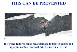
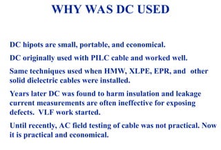
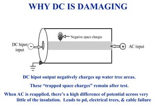
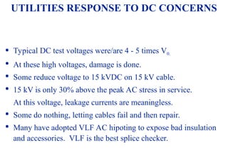
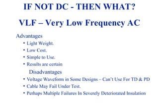

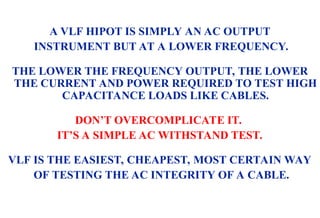
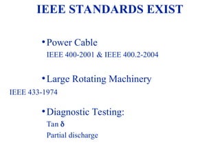
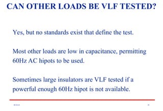
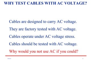
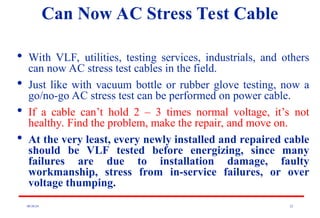
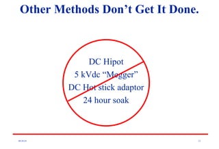
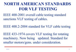
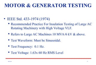
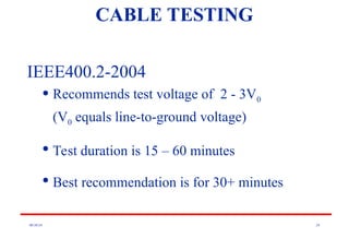
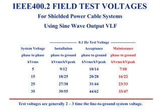
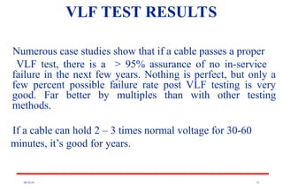
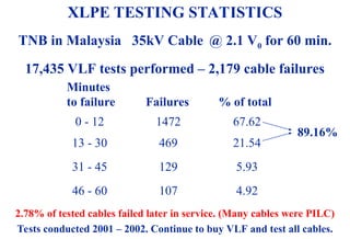
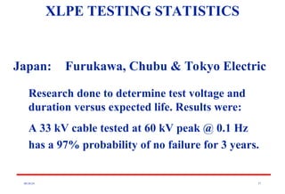
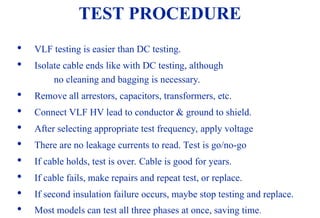
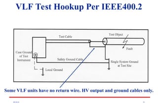
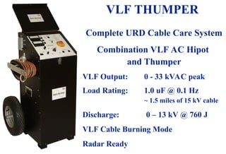
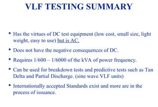
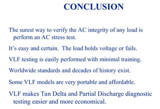
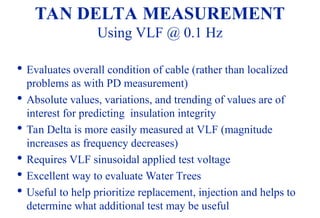

The document discusses the advantages of very low frequency (vlf) cable testing over traditional direct current (dc) testing, highlighting how dc can damage insulation and lead to failures. It details the principles of vlf testing, including its applications and effectiveness in identifying cable issues, and outlines relevant IEEE standards for testing procedures. Numerous field studies and statistical results demonstrate vlf testing's reliability, showing a high assurance of no in-service failures for cables that pass the test.


