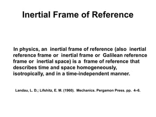
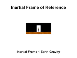
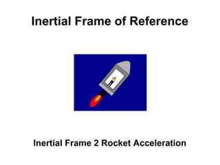
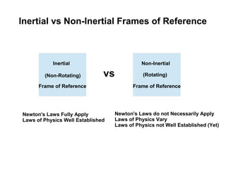
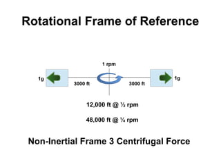
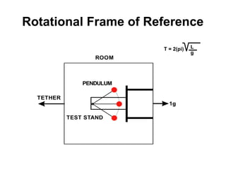
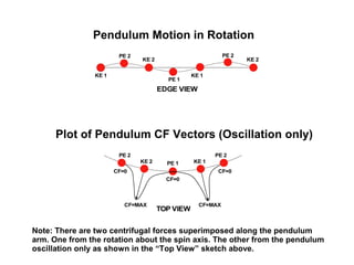
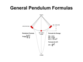
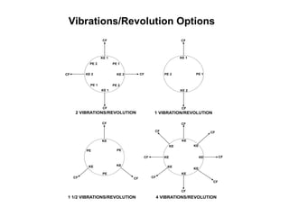
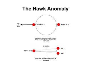
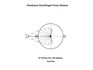
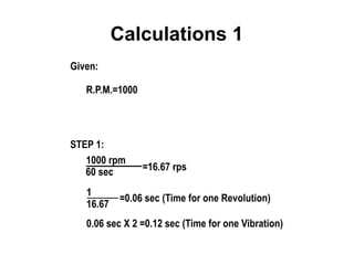
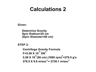
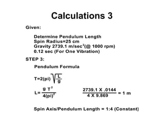
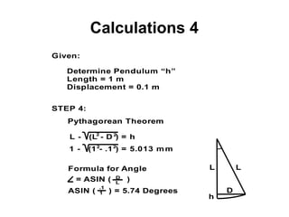
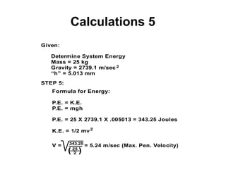
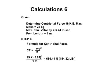
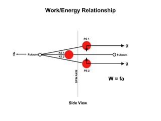
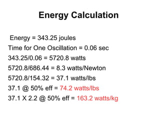
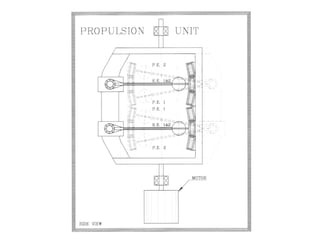
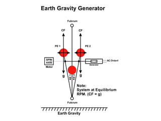
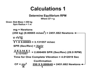
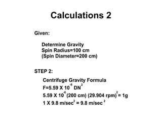
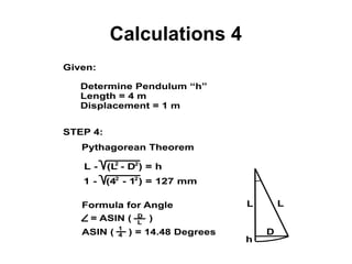
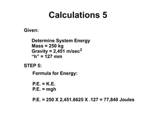
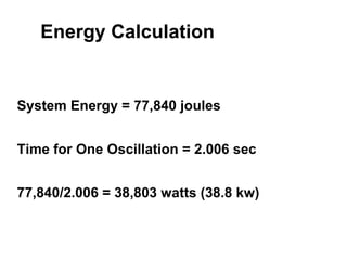
This document presents theoretical models for reactionless propulsion and an Earth gravity generator. It discusses inertial and non-inertial frames of reference and how the laws of physics vary between them. The reactionless propulsion model uses a pendulum within a rotating reference frame, where the centrifugal force vectors could potentially cancel out. Calculations determine the system energy and centrifugal forces for different parameters. The Earth gravity generator model places a bob on a spinning axis, where the centrifugal force counteracts gravity at a specific equilibrium RPM.
2. PROLOGUE
These mathematical models are presented here as theoretical concepts
that may, or not, represent actual workable mechanizes. According to
the present, well established view of the existing laws of physics, they will
not work. It is the view of this author that the existing laws of physics,
which are based on the the Inertial Frame of Reference, need to be modified
in order to reflect the dynamics within the Non-inertial Frame of Reference.
It is to this end that this work is hereby presented for others to evaluate.
3. Chapter 1
Chapter 2
Chapter 3
Distinction
Inertial Frame of Reference
vs
Non-inertial Frame of Reference
Mathematical Model
Reactionless Propulsion
Mathematical Model
Earth Gravity Generator
4. “The only way of discovering the limits
of the possible is to venture a little way
past them into the impossible.”
Arthur C. Clarke (Clarke's second law)
“In order to do the impossible,
you must see the invisible”
David Murdock
“Conventional wisdom leads to stagnation.
Unconventional wisdom leads to advancement.”
Elijah Hawk
6. Inertial Frame of Reference
In physics, an inertial frame of reference (also inertial
reference frame or inertial frame or Galilean reference
frame or inertial space) is a frame of reference that
describes time and space homogeneously,
isotropically, and in a time-independent manner.
Landau, L. D.; Lifshitz, E. M. (1960). Mechanics. Pergamon Press. pp. 4–6.
9. Rotational Frame of Reference
Non-Inertial Frame 3 Centrifugal Force
3000 ft 3000 ft
1 rpm
1g1g
12,000 ft @ ½ rpm
48,000 ft @ ¼ rpm
10. Centrifugal Force (Rotating Reference Frame)
In classical mechanics, the centrifugal force
is an outward force which arises when
describing the motion of objects in a
rotating reference frame. Because a rotating
frame is an example of a non-inertial
reference frame, Newton's laws of motion do
not accurately describe the dynamics within
the rotating frame. (John Robert Taylor)
11. Einstein's Principle of Equivalence
The equivalence principle was properly introduced by Albert Einstein in
1907, when he observed that the acceleration of bodies towards the
center of the Earth at a rate of 1g (g = 9.81 m/s2 being a standard
reference of gravitational acceleration at the Earth's surface) is
equivalent to the acceleration of an inertially moving body that would
be observed on a rocket in free space being accelerated at a rate of 1g.
Einstein stated it thus:
“We assume the complete physical equivalence of a gravitational field
and a corresponding acceleration of the reference system”.
—Einstein, 1907
12. The Hawk Principle of Equivalence
All Three Frames of Reference Affect Mass Proportionately the Same
Inertial Frame 1 Earth Gravity
Inertial Frame 2 Rocket Acceleration
Non-Inertial Frame 3 Centrifugal Force
The Hawk Equivalency
13. Newton's Laws/Inertial Frames
The laws of Newtonian mechanics do not always hold in
their simplest form.... Newton's laws hold in their simplest
form only in a family of reference frames, called inertial
frames. This fact represents the essence of the Galilean
principle of relativity: ”The laws of mechanics have the
same form in all inertial frames”.
Milutin Blagojević: Gravitation and Gauge Symmetries, p. 4
14. The Laws of Physics Vary
Physical laws take the same form in all inertial frames. By
contrast, in a non-inertial reference frame the laws of
physics vary depending on the acceleration of that frame
with respect to an inertial frame, and the usual physical
forces must be supplemented by fictional forces.
Milton A. Rothman (1989). . Courier Dover Publications. p. 23
Sidney Borowitz & Lawrence A. Bornstein (1968). A Commentary View of Physics
15. Spiral Galaxies
Modified Newtonian Dynamics (MOND) is a hypothesis
advanced by Mordehai Milgrom (Milgrom, 1993) in order to
explain the anomalous rotation of spiral galaxies. Many
such galaxies do not appear to obey Newton's law of
gravitational attraction....
EarthTech International Website http://earthtech.org/mond/ Harold Puthoff, Ph.D
16. Inertial vs Non-Inertial Frames of Reference
Inertial
Frame of Reference
Non-Inertial
(Rotating)
Frame of Reference
vs
Newton's Laws Fully Apply
Laws of Physics Well Established
Newton's Laws do not Necessarily Apply
Laws of Physics Vary
Laws of Physics not Well Established (Yet)
(Non-Rotating)
18. Pendulum Definitions
1) Displacement: At any moment, the distance of
bob from mean position. It is a vector quantity.
2) Amplitude: Maximum displacement on either
side of the mean position.
3) Vibration: Motion from the mean position to one
extreme, then to the other extreme and then back
to the mean position. (Time Period = “T”)
4) Oscillation: Motion from one extreme to the
other extreme. One Oscillation is half Vibration.
19. Rotational Frame of Reference
Non-Inertial Frame 3 Centrifugal Force
3000 ft 3000 ft
1 rpm
1g1g
12,000 ft @ ½ rpm
48,000 ft @ ¼ rpm
20. Rotational Frame of Reference
ROOM
TETHER
TEST STAND
PENDULUM
1g
T = 2(pi) L
g
21. KE 1
KE 2
PE 1
PE 2
KE 1
PE 2
KE 2
EDGE VIEW
KE 1PE 1KE 2
PE 2 PE 2
TOP VIEW
CF=0
CF=0
CF=0
CF=MAXCF=MAX
Pendulum Motion in Rotation
Plot of Pendulum CF Vectors (Oscillation only)
Note: There are two centrifugal forces superimposed along the pendulum
arm. One from the rotation about the spin axis. The other from the pendulum
oscillation only as shown in the “Top View” sketch above.
27. Calculations 2
Given:
Determine Gravity
Spin Radius=25 cm
(Spin Diameter=50 cm)
STEP 2:
Centrifuge Gravity Formula
F=5.59 X 10 DN
-6 2
5.59 X 10 (50 cm) (1000 rpm) =279.5 g’s
2-6
279.5 X 9.8 m/sec = 2739.1 m/sec
2 2
28. Calculations 3
Given:
Determine Pendulum Length
Spin Radius=25 cm
Gravity 2739.1 m/sec
STEP 3:
2
Pendulum Formula
T=2(pi)
L
g
L=
g
4(pi)
2739.1 X .0144
= 1 m
0.12 sec (For One Vibration)
(@ 1000 rpm)
Spin Axis/Pendulum Length = 1:4 (Constant)
T
2
2
4 X 9.869
29. Calculations 4
Given:
Determine Pendulum “h”
Length = 1 m
Displacement = 0.1 m
STEP 4:
Pythagorean Theorem
L - (L - D ) = h2
1 - (1 - .1 ) = 5.013 mm
L
D
h
LFormula for Angle
= ASIN ( )D
L
ASIN ( ) = 5.74 Degrees
.1
1
2
2 2
30. Calculations 5
Given:
Determine System Energy
Mass = 25 kg
Gravity = 2739.1 m/sec
“h” = 5.013 mm
STEP 5:
Formula for Energy:
P.E. = K.E.
P.E. = mgh
P.E. = 25 X 2739.1 X .005013 = 343.25 Joules
K.E. = 1/2 mv
2
2
V = = 5.24 m/sec (Max. Pen. Velocity)343.25
25
2( )
31. Calculations 6
Given:
Determine Centripital Force @ K.E. Max.
Mass = 25 kg
Max. Pen. Velocity = 5.24 m/sec
Pen. Length = 1 m
STEP 6:
Formula for Centripital Force:
CF =
2
mv
R
25 X (5.24)
1 m
= 686.44 N (154.32 LBf)
2
37. Continuous 1g Space Travel
Destination Time MPH @ Mid Point
Moon 3.5 Hrs 136,947 MPH
Mars 2.08 Days 1,956,445 MPH
Jupiter 5.88 Days 5,540,258 MPH
Saturn 8.38 Days 7,897,326 MPH
Uranus 12.23 Days 11,523,886 MPH
Neptune 15.46 Days 14,567,166 MPH
Pluto 17.17 Days 16,748,180 MPH
39. g g
Fulcrum
Fulcrum
PE 1 PE 2
KE2
KE1
SPIN
AXIS
Earth Gravity
Earth Gravity Generator
AC Output
Generator
CF CF
Note:
System at Equilibrium
RPM. (CF = g)
Motor