Downloaded 148 times

![414 Chapter 8
PROBLEM SOLUTIONS
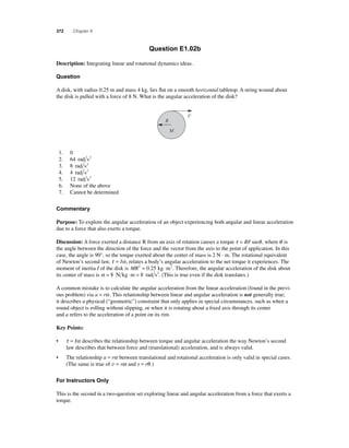
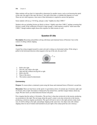
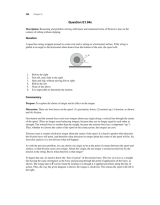
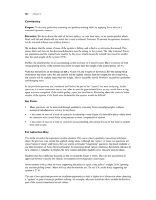
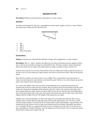
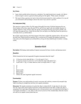
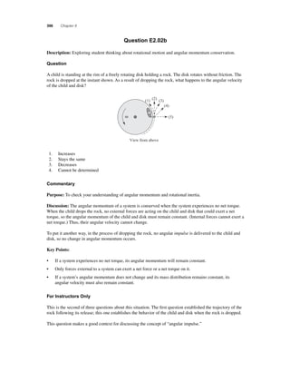
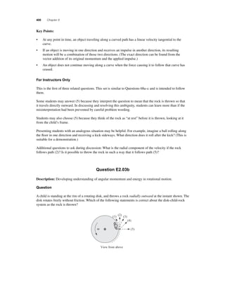
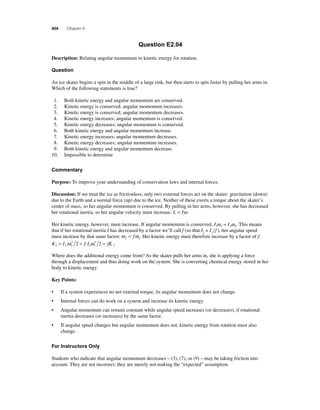
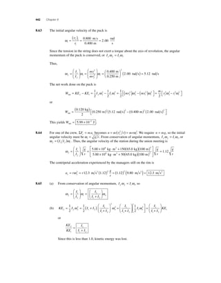
8.1 Since the friction force is tangential to a point on the rim of the wheel, it is perpendicular to the
radius line connecting this point with the center of the wheel. The torque of this force about
the axis through the center of the wheel is then τ = rf sin 90.0° = rf , and the friction force is
f
= τ = 76 0 ⋅ =
r
217
. N m
0.350 m
N
8.2 The torque of the applied force is τ = rFsinθ . Thus, if r = 0.330 m, θ = 75.0°, and the torque has
the maximum allowed value of τ max = 65.0 N⋅m, the applied force is
F
τ =
= = ⋅
r
( ) °
max
sin
θ
.
sin .
65 0
75 0
204
N m
0.330 m
N
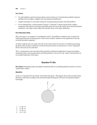
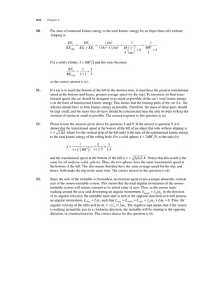
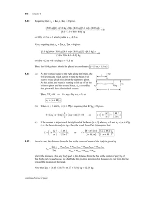
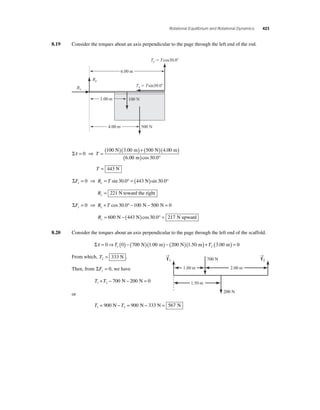
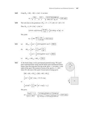
8.3 First resolve all of the forces shown in Figure P8.3 into components parallel to and perpendicular
to the beam as shown in the sketch below.
(30 N)cos45°
O C
(25 N)cos30°
(25 N)sin30° (10 N)cos20°
(30 N)sin45° 2.0 m
(10 N)sin20°
4.0 m
(a) τ O = + ( ) ° ⎡⎣
25 N cos 30 2.0 m 10 N sin 20° (4.0 m) = +30 N⋅m
⎤⎦
( ) − ( ) ⎡⎣
⎤⎦
or τ O= 30 N⋅m counterclockwise
(b) τ C = + ( ) ⎡⎣
30 N sin 45 2.0 m 10 N sin 20° (2.0 m) = +36 N⋅m
° ( ) − ( ) ⎡⎣
⎤⎦
⎤⎦
or τ C= 36 N⋅m counterclockwise
8.4 The lever arm is d = (1.20 × 10⁻² m)cos 48.0° = 8.03 × 10⁻³ m, and the torque is
τ = Fd = (80.0 N)(8.03 ×10⁻³ m) = 0.642 N⋅m counterclockwise
8.5 (a) τ = F ⋅ (lever arm) = (mg)⋅[ θ ] g sin
= ( )( )⋅ ( ) ⎡⎣
3.0 kg 9.8 m s2 2.0 m sin 5.0° = 5.1 N⋅⋅m
⎤⎦
Pivot
q
Fg mg
q
(b) The magnitude of the torque is proportional to the sinθ , where θ is the angle between the
direction of the force and the line from the pivot to the point where the force acts. Note from
the sketch that this is the same as the angle the pendulum string makes with the vertical.
Since sinθ increases as θ increases, the torque also increases with the angle.](https://image.slidesharecdn.com/ismchapter8-140820140722-phpapp01/85/Solucionario-Fundamentos-de-Fisica-Serway-9na-edicion-Capitulo-8-46-320.jpg)
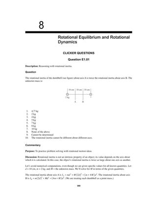
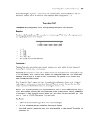
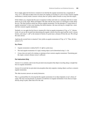
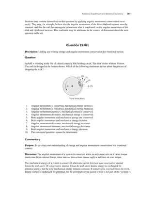
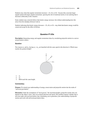
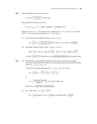
![Rotational Equilibrium and Rotational Dynamics 415
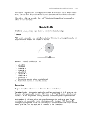
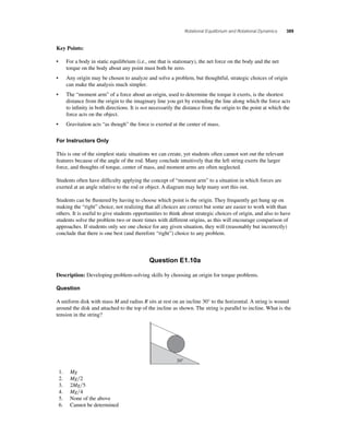
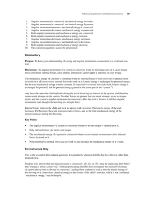
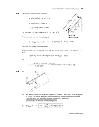
8.6 The object is in both translational and rotational equilibrium. Thus, we may write:
ΣFx = 0 ⇒ Fx − Rx = 0
ΣF F R F y y y g = 0 ⇒ + − = 0
and
Στ = ⎜
⎛⎝ ⇒ F ( cos θ )− F ( sin θ )− F cos θ ⎟ = 0
O y x g ⎞⎠
0
2
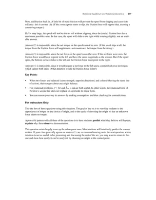
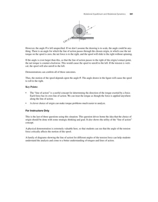
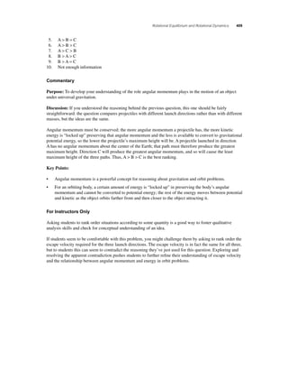
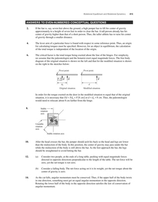
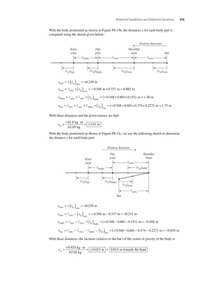
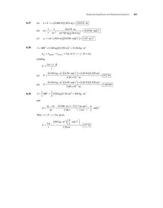
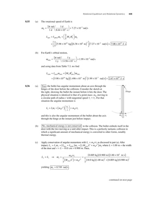
8.7
0.080 m
FtyFt sin12.0°
FtxFt cos12.0°
0.290 m
Pivot 41.5 N
Requiring that Στ = 0, using the shoulder joint at point O as a pivot, gives
Στ = (F °)( ) − ( )( ) = t sin12.0 0.080 m 41.5 N 0.290 m 0, or Ft = 724 N
Τhen ΣFy= 0 ⇒ −F + ( ) ° − sy 724 N sin12.0 41.5 N = 0, yielding Fsy = 109 N.
ΣFx = 0 gives Fsx − (724 N)cos12.0° =0, or Fsx = 708 N
Therefore,
F F F s sx sy = 2 + 2 = ( )2 + ( )2 = 708 N 109 N 716 N
8.8 (a) Since the beam is in equilibrium, we choose the center
as our pivot point and require that
Στ ) = − ( ) + ( ) = center Sam Joe F 2.80 m F 1.80 m 0
or
F F Joe Sam = 1.56 [1]
Also,
ΣF F F y= 0 ⇒ + = 450 N Sam Joe [2]
Substitute Equation [1] into [2] to get the following:
F F Sam Sam + 1.56 = 450 N or FSam
x 2.80 m y 1.80 m
x y
FSam FJoe
= 450
N
= N 2.56
176
Then, Equation [1] yields FJoe = 1.56(176 N) = 274 N .
Fsx
Fsy
Fsy
Fsx
q
→
Fs
Fg 450 N
continued on next page](https://image.slidesharecdn.com/ismchapter8-140820140722-phpapp01/85/Solucionario-Fundamentos-de-Fisica-Serway-9na-edicion-Capitulo-8-47-320.jpg)
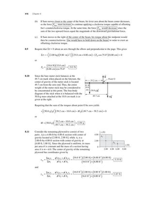
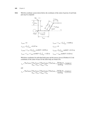
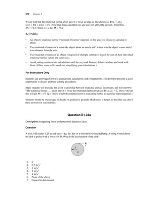
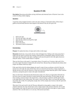
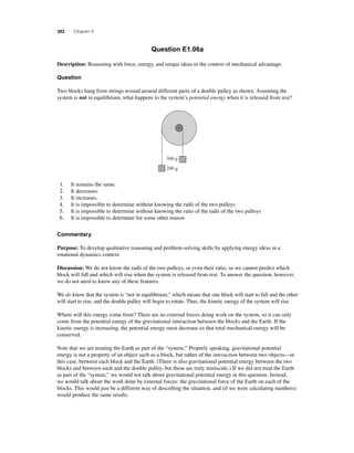
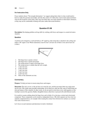
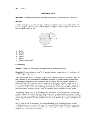
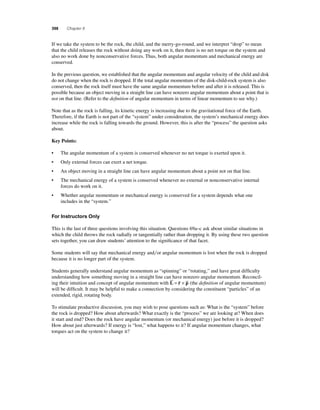
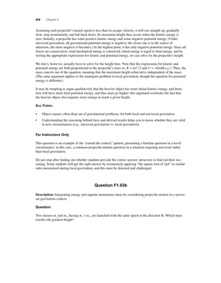
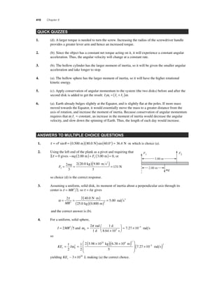
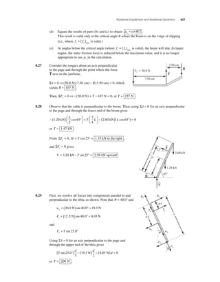
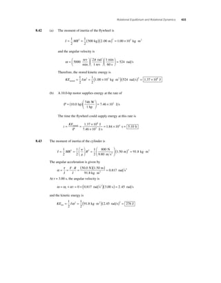
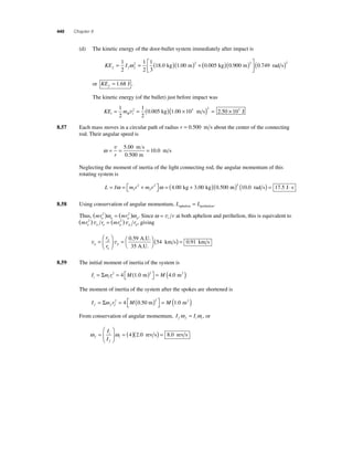
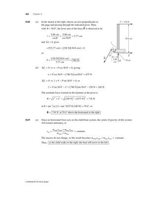
![422 Chapter 8
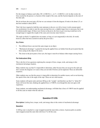
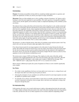
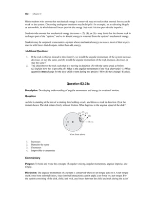
8 .18 In the free-body diagram of the foot
given at the right, note that the force
R
(exerted on the foot by the tibia)
has been replaced by its horizontal
and vertical components. Employ-ing
both conditions of equilibrium
(using point O as the pivot point)
gives the following three equations:
ΣF R T x= 0 ⇒ sin15.0° − sinθ = 0
or
R
T =
θ
15 0
°
sin
sin .
[1]
18.0 cm
T →
⎡⎣
ΣF = 0 ⇒ 700 N − R cos15.0° + T cosθ = 0 [2]
yΣτ = 0 ⇒ − ( 700 N ) ( 18.0 cm ) cos θ + T (25.0 cm − 18.0 cm) = 0
O ⎤⎦
or
T = (1 800 N)cosθ [3]
Substituting Equation [3] into Equation [1] gives
R =
°
⎛⎝ ⎜
⎞⎠ ⎟
1 800
15 0
N
sin .
sinθ cosθ [4]
Substituting Equations [3] and [4] into Equation [2] yields
1 800
15 0
N
1 800 N
2 tan .
sin cos cos
°
⎛⎝ ⎜
⎞⎠ ⎟
θ θ − ( ) θ = 700 N
which reduces to: sinθ cosθ = (tan15.0°)cos2θ + 0.104 2.
Squaring this result and using the identity sin2θ = 1− cos2θ gives
tan . cos tan . . 2 4 15 0 1 2 15 0 0 104 2 ° ( ) + ⎡⎣
⎤⎦
+ ° ( )( ) − θ 1 0 104 2 0 2 2 ⎡⎣
⎤⎦
cos + ( . ) =
In this last result, let u = cos2θ and evaluate the constants to obtain the quadratic equation
(1.071 8)u2 − (0.944 2)u + (0.010 9) = 0
The quadratic formula yields the solutions u = 0.869 3 and u = 0.011 7.
Thus,
θ = cos−1 ( 0.869 3) = 21.2° or θ = cos−1 ( 0.011 7) = 83.8°
We ignore the second solution since it is physically impossible for the human foot to stand with
the sole inclined at 83.8° to the fl oor. We are the left with: θ = 21.2° .
Equation [3] then yields
T = (1 800 N)cos 21.2° = 1.68 ×10³ N
and Equation [1] gives
R =
( × ) °
°
= ×
1 68 10 21 2
15 0
2 34 10
3
3 . sin .
sin .
.
N
N
Rx Rsin15.0
Ry Rcos15.0
n700 N
25.0 cm
Point O
q
q](https://image.slidesharecdn.com/ismchapter8-140820140722-phpapp01/85/Solucionario-Fundamentos-de-Fisica-Serway-9na-edicion-Capitulo-8-54-320.jpg)
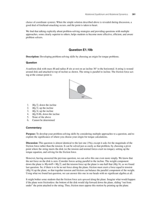
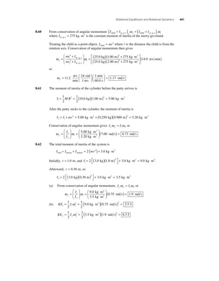
 = 0
which gives xmax = 5.14 m .
→
T1
T2
T3
0.500 m
1.00 m
40.0°
1.00 m
mg 294 N
700 N](https://image.slidesharecdn.com/ismchapter8-140820140722-phpapp01/85/Solucionario-Fundamentos-de-Fisica-Serway-9na-edicion-Capitulo-8-56-320.jpg)
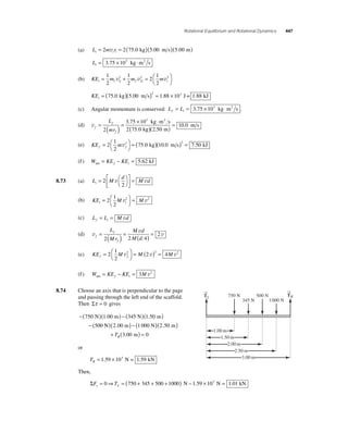
![426 Chapter 8
(d) Solving the above result for the tension in the cable gives
T
=( mg 2
) L
=
mg L
θ 2
θ
θ
cos
sin tan
or
=( kg )( m s
)
T °
=
16 0 9 80
2 300
136
. .
tan .
N
2
(e) ΣF F T x x = 0 ⇒ − = 0 and ΣF F mg y y = 0 ⇒ − = 0
(f ) Solving the above results for the components of the hinge force gives
F T x= =136 N and F mg y= = (16.0 kg)(9.80 m s2 ) = 157 N
(g) Attaching the cable higher up would allow the cable to bear some of the weight, thereby
reducing the stress on the hinge. It would also reduce the tension in the cable.
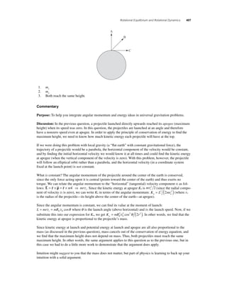
8.25 Consider the free-body diagram of the
material making up the center point in
the rope given at the right. Since this
material is in equilibrium, it is necessary
to have ΣF ΣF x y = 0 and = 0, giving
ΣFx = 0: +T −T = 2 1 sinθ sinθ 0
6.00 m
q q
or T T 2 1 = , meaning that the rope has a uniform tension T throughout its length.
ΣFy = 0: T cosθ +T cosθ − 475 N = 0 where cos
6.00 m
0 500
.
m
.
θ =
( )+( )
0 500 2 2
6.00 m m
and the tension in the rope (force applied to the car) is
T= =475 (475 ) ( ) + (0 500 )
N kN ( ) = . × = .
2 0
2 2
N
2 cos
N 6.00 m m
θ
.
.500
2 86 103 2 86
m
8.26 (a)
(b) Στ θ θ ) = ⇒ + − ⎛⎝
⎞⎠
lower 0 0 0
+
end
2
mg
L
cos T (L sin ) = 0
or T
⎛
cot θ
θ
cos
sin
mg mg =
⎝ ⎜
⎞
⎠ ⎟
=
2 2
θ
(c) ΣF T n x s = 0 ⇒ − +μ = 0 or T n s = μ [1]
ΣF n mg y= 0 ⇒ − = 0 or n = mg [2]
Substitute Equation [2] into [1] to obtain T mg s = μ .
0.500 m
T1 T2
F 475 N
n
T
mg
fs ( fs)max msn
L/2
L/2
q
continued on next page](https://image.slidesharecdn.com/ismchapter8-140820140722-phpapp01/85/Solucionario-Fundamentos-de-Fisica-Serway-9na-edicion-Capitulo-8-58-320.jpg)
![Rotational Equilibrium and Rotational Dynamics 429
net m = ⇒ = = ° = ( ) I I
τ
α α net
8.33 (a) τ α
2 ( )= ⋅
rF sin 90 0.330 250
0 940
87 8
N
rad s
kg m 2
.
.
(b) For a solid cylinder, I = Mr2 2, so
M
I
r
= =
( ⋅ )
( )
3 .
.
= × 2 2 878
1 61 10 2 2
0 330
.
kg m
m
kg
2
(c) ω =ω +α = + ( )( ) = 0 t 0 0.940 rad s2 5.00 s 4.70 rad s
8.34 (a) I = 2I + I = 2(MR2 2)+ mr2 2
disk cylinder or I = MR2 + mr2 2
(b) τ g = 0 Since the line of action of the gravitational force passes through the rotation axis, it
has zero lever arm about this axis and zero torque.
(c) The torque due to the tension force is positive. Imagine gripping the cylinder with your
right hand so your fi ngers on the front side of the cylinder point upward in the direction of
the tension force. The thumb of your right hand then points toward the left (positive direc-tion)
along the rotation axis. Because
s = I` , the torque and angular acceleration
have the same direction. Thus, a positive torque produces a positive angular acceleration.
When released, the center of mass of the yoyo drops downward, in the negative direction.
The translational acceleration is negative.
(d) Since, with the chosen sign convention, the translational acceleration is negative when
the angular acceleration is positive, we must include a negative sign in the proportionality
between these two quantities. Thus, we write: a = −rα or α = −a r
(e) Translation:
ΣF m a T M m g M ma y= ⇒ − ( + ) = ( + ) total 2 2 [1]
(f ) Rotational:
Στ = Iα ⇒ rT sin 90° = Iα or rT = Iα [2]
(g) Substitute the results of (d) and (a) into Equation [2] to obtain
T I
r
I
a r
r
MR
mr a
r
= ⎛⎝
⎞⎠
= − ⎛⎝⎞⎠
⎛
= − +
⎝ ⎜
⎞
⎠ ⎟
α 2
2
2 2
or T M
R
r
m
a = − ⎛⎝
⎞⎠
+
⎡
⎣ ⎢
⎤
⎦ ⎥
2
2
[3]
Substituting Equation [3] into [1] yields
− ( ) + ⎡⎣
⎤⎦
M R r m a − ( M + m) g = ( M + m)a 2 2 2 2 or a
M m g
M M Rr m
=
−( 2
+ )
+ ( ) +
2 3 2 2
(h) a =
2 2 00 1 00 (9 80 )
− ( ) + ⎡⎣
⎤⎦
2 200
. . .
.
kg kg m s
kg
2
2 72 2 . . . .
( )+( )( )+( )
= −
2 00 10 0 4 00 3 1 00 2
.
kg kg
m s2
(i) From Equation [1],T = (2M + m)(g + a) = (5.00 kg)(9.80 m s2 − 2.72 m s2 ) = 35.4 N .
( j) Δ
=( )+ ( Δ
) ⇒ = =
y t at t
y
a
(− )
−
0 2
2 2 1 00
2 72
2
. m
. m s
s 2 = 0.857](https://image.slidesharecdn.com/ismchapter8-140820140722-phpapp01/85/Solucionario-Fundamentos-de-Fisica-Serway-9na-edicion-Capitulo-8-61-320.jpg)
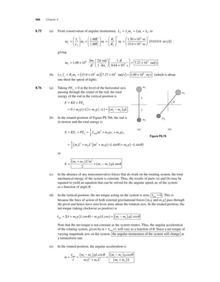
![430 Chapter 8
8 .35 (a) Consider the free-body diagrams of the cylinder and man given at the
right. Note that we shall adopt a sign convention with clockwise and
downward as the positive directions. Thus, both a and α are positive in
the indicated directions and a = rα . We apply the appropriate form of
Newton’s second law to each diagram to obtain the following:
Rotation of Cylinder: τ = Iα ⇒ rT sin 90° = Iα , or T = Iα r,
so
T
r
Mr
a
r
= ⎛⎝ ⎜
⎞⎠ ⎟
⎛⎝ ⎜
⎞⎠ ⎟
1 1
2
2 and T = Ma 1
2
[1]
Translation of man:
a
ΣF ma mg T ma y= ⇒ − = or T = m(g − a) [2]
2 Ma = m(g − a), or
Equating Equations [1] and [2] gives 1
a
mg
m M
=
+
=( 75 . 0 kg )( 9 .
80
m s
2
)
2
75 .
0
kg+ 225 kg 2
( )= 3.92 m s2
(b) From a = rα , we have
α= = = a
r
3 92
0 400
9 80
.
.
.
m s
m
rad s
2
2
(c) As the rope leaves the cylinder, the mass of the cylinder decreases, thereby
decreasing the moment of inertia. At the same time, the weight of the rope leaving
the cylinder would increase the downward force acting tangential to the cylinder,
and hence increase the torque exerted on the cylinder. Both of these effects
will cause the acceleration of the system to increase with time. (The increase would be
slight in this case, given the large mass of the cylinder.)
8.36 The angular acceleration is α = (ω − ω ) = − (ω ) f i i Δt Δt since ω f = 0.
Thus, the torque is τ = Iα = − Iω t i ( Δ ). But, the torque is also τ = − fr, so the magnitude of the
required friction force is
f
I
r t
= i ( ) =
( kg ⋅ m )( rev min
)
( )
ω
Δ
12 50
0 50 m
6 0
2
. . s
2 rad
1
= 1 rev
min
60 s
⎛⎝
⎞⎠
⎛⎝
⎞⎠
( )
21
N π
Therefore, the coeffi cient of friction is
μk
= = = 21
f
n
0 30
N
70 N
.
M
m
mg
a
r
T
T](https://image.slidesharecdn.com/ismchapter8-140820140722-phpapp01/85/Solucionario-Fundamentos-de-Fisica-Serway-9na-edicion-Capitulo-8-62-320.jpg)
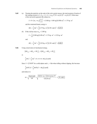
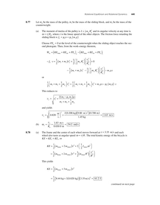
![432 Chapter 8
8 .40 (a) It is necessary that the tensions T1 and T2 be different in order
to provide a net torque about the axis of the pulley
and produce an angular acceleration of the pulley. Since
intuition tells us that the system will accelerate in the direc-tions
shown in the diagrams at the right when m m 2 1 , it is
necessary that T T 2 1 .
(b) We adopt a sign convention for each object with the positive
direction being the indicated direction of the acceleration of
that object in the diagrams at the right. Then, apply Newton’s
second law to each object:
r
T2
T2
a a
For m F ma T mg ma 1 y 1 1 1 1 : Σ = ⇒ − = or T m g a 1 1 = ( + ) [1]
For m F ma mg T ma 2 y 2 2 2 2 : Σ = ⇒ − = or T m g a 2 2 = ( − ) [2]
For M: Στ = Iα ⇒ rT − rT = Iα 2 1 or T T I r 2 1 − = α [3]
Substitute Equations [1] and [2], along with the relations I = Mr2 2 and α = a r , into
Equation [3] to obtain
m g a m g a
Mr
r
a
r
Ma
2 1
2
2 2
− ( ) − + ( ) = ⎛⎝ ⎜
⎞⎠ ⎟
+ + ⎛⎝ ⎜
= or m m
M
⎞⎠ ⎟
= ( − )
a m m g 1 2 2 1 2
and
a
( − ) 2 1
m m g
m m M
=
( − )
+ +
=
1 2 2
m s ( )
20.0 kg 10.0 kg 9.80 m s2
2
+ ( ) =
kg kg + 8.00 kg
20 0 10 0 2
2 88
. .
.
(c) From Equation [1]: T1 = (10.0 kg)(9.80 m s2 + 2.88 m s2 ) = 127 N .
From Equation [2]: T2 = (20.0 kg)(9.80 m s2 − 2.88 m s2 ) = 138 N .
8.41 The initial angular velocity of the wheel is zero, and the fi nal angular velocity is
= = = v 5
ω f r
1
40 0
0.0 m s
.25 m
. rad s
Hence, the angular acceleration is
α
ω −
ω
=
f i
= 40 0 − 0
= Δt
0 480
83 3
.
.
.
rad s
s
rad s2
The torque acting on the wheel is τ = f ⋅ r k , so τ = Iα gives
f
( ⋅ )( )α = × 110 83 3
I
r k= =
7 33 1
2 . 2
kg m rad s
1.25 m
. 03 N
Thus, the coeffi cient of friction is
μk
= = ×
k f
n
= 7 33 10
×
10
0 524
3
4
.
.
N
1.40 N
M
m1 m2
m1g m2g
T1
T1
a](https://image.slidesharecdn.com/ismchapter8-140820140722-phpapp01/85/Solucionario-Fundamentos-de-Fisica-Serway-9na-edicion-Capitulo-8-64-320.jpg)
![434 Chapter 8
8.44 (a) Hoop: I = MR2 = ( )( )2 = ⋅ 4.80 kg 0.230 m 0.254 kg m2
Solid Cylinder: I = MR = ( )( ) = ⋅ 1
2
1
2
2 4 80 0 230 2 0 127 . kg . m . kg m2
Solid Sphere: I = MR = ( )( ) = ⋅ 2
5
2
5
2 4 80 0 230 2 0 102 . kg . m . kg m2
Thin, Spherical, Shell: I = MR = ( )( ) = ⋅ 2
3
2
3
2 4 80 0 230 2 0 169 . kg . m . kg m2
(b) When different objects of mass M and radius R roll
without slipping (⇒ a = Rα ) down a ramp, the one with
the largest translational acceleration a will have the
highest translational speed at the bottom. To determine
the translational acceleration for the various objects,
consider the free-body diagram at the right:
ΣF Ma Mg f Ma x= ⇒ sinθ − = [1]
τ = Iα ⇒ f R = I (a R) or f = Ia R2 [2]
Substitute Equation [2] into [1] to obtain
Mg sinθ − Ia R2 = Ma or a
Mg
M I R
=
+
sinθ
2
n
a
Mg
a
x
f
R
q
q
M
Since M, R, g, and θ are the same for all of the objects, we see that the translational accel-eration
(and hence the translational speed) increases as the moment of inertia decreases.
Thus, the proper rankings from highest to lowest by translational speed will be:
solid sphere; solid cylinder; thin, spherical, shell; and hoop
(c) When an object rolls down the ramp without slipping, the friction force does no work and
mechanical energy is conserved. Then, the total kinetic energy gained equals the gravitational
potential energy given up: KE + KE = −Δ PE = Mgh and KE = Mgh −1
M v2, where
r t g r2
h is the vertical drop of the ramp and v is the translational speed at the bottom. Since M,
g, and h are the same for all of the objects, the rotational kinetic energy decreases as the
translational speed increases. Using this fact, along with the result of Part (b), we rank the
object’s fi nal rotational kinetic energies, from highest to lowest, as:
hoop; thin, spherical, shell; solid cylinder; and solid sphere](https://image.slidesharecdn.com/ismchapter8-140820140722-phpapp01/85/Solucionario-Fundamentos-de-Fisica-Serway-9na-edicion-Capitulo-8-66-320.jpg)
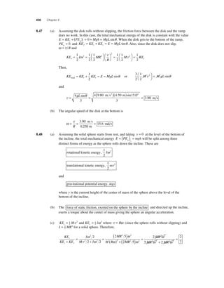
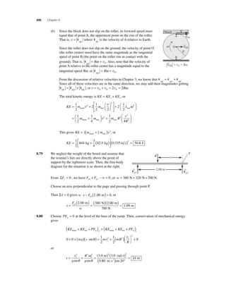
![438 Chapter 8
8 .53 (a) The arm consists of a uniform rod of 10.0 m length and the mass of the seats at the lower
end is negligible. The center of gravity of this system is then located at the
geometric center of the arm, located 5.00 m from the upper end .
From the sketch at the right, the height of the center of gravity above the zero level is
ycg = 10.0 m − (5.00 m)cosθ .
(b) When θ = 45.0°, ycg = 10.0 m − (5.00 m)cos 45.0° = 6.46 m
and
PE mgy g= =( )( )( )= × cg
365 kg 9.80 m s2 6.46 m 2.31 104 J
(c) In the vertical orientation, θ = 0° and cosθ = 1, giving
ycg = 10.0 m − 5.00 m = 5.00 m. Then,
PE mgy g= =( )( )( )= × cg
365 kg 9.80 m s2 5.00 m 1.79 104 J
(d) Using conservation of mechanical energy as the arm starts
from rest in the 45° orientation and rotates about the upper
end to the vertical orientation gives
1
2
I 2 mg y 0 mg y end f cg f cg i ω + ( ) = + ( ) or ω f
ycg
mg y y
i f
I
=
( ) − ( ) ⎡⎣⎢
⎤⎦⎥
2 cg cg
end
[1]
For a long, thin rod: I mL end = 2 3. Equation [1] then becomes
ω f
2 ( ) − (
cg cg cg cg ) ⎡⎣⎢
mg y y
i f i
mL
g y y
=
( ) − ( ) ⎡⎣⎢
⎤⎦⎥
=
3
6
2
⎤⎦⎥
= ( )( − )
f
L2
m s2 m m
6 9 . 80 6 . 46 5 .
00
( = 0.927
rad s 10 .
0
m
) 2 Then, from v = rω, the translational speed of the seats at the lower end of the rod is
v = (10.0 m)(0.927 rad s) = 9.27 m s
8.54 (a) L = Iω = (MR2 )ω = ( )( )2 ( ) = 2.40 kg 0.180 m 35.0 rad s 2.72 kg ⋅m2 s
(b) L I MR = =⎛⎝ ⎜
⎞⎠ ⎟
ω ω = ( )( ) 1
2
1
2
2 2 40 0 180 2 35 0 . kg . m ( . rad s) = 1.36 kg ⋅m2 s
(c) L I MR = =⎛⎝ ⎜
⎞⎠ ⎟
ω ω = ( )( ) 2
5
2
5
2 2 40 0 180 2 35 0 . kg . m ( . rad s) = 1.09 kg ⋅m2 s
(d) L I MR = =⎛⎝ ⎜
⎞⎠ ⎟
ω ω = ( )( ) 2
3
2
3
2 2 40 0 180 2 35 0 . kg . m ( . rad s) = 1.81 kg ⋅m2 s
mg
cg
10.0 m
5.00 m
q](https://image.slidesharecdn.com/ismchapter8-140820140722-phpapp01/85/Solucionario-Fundamentos-de-Fisica-Serway-9na-edicion-Capitulo-8-70-320.jpg)
![446 Chapter 8
8 .71 If the ladder is on the verge of slipping, f f n s s = ( ) = max μ at both the
fl oor and the wall.
From ΣFx = 0, we fi nd f n 1 2 − = 0, or
n n2 s 1 = μ [1]
Also, ΣFy = 0 gives n w n1 s 2 − + μ = 0.
Using Equation [1], this becomes
n w n 1 s s 1 − + μ (μ ) = 0
or
n
w w
w
= 0 80
1 1 2 1 25
s
+
= =
μ .
. 0 [2]
Thus, Equation [1] gives
n w w 2 = 0.500(0.800 ) = 0.400 [3]
Choose an axis perpendicular to the page and passing through the lower end of the ladder. Then,
Στ = 0 yields
− ⎛⎝ ⎜
⎞⎠ ⎟
L
w + n ( L ) + f ( L
) =
2
0 2 2 cosθ sinθ cosθ
Making the substitutions n w 2 = 0.400 and f n w 2 s 2 = μ = 0.200 , this becomes
− ⎛⎝ ⎜
⎞⎠ ⎟
L
w + ( )( ) + ( )
w L w L
2
cosθ 0.400 sinθ 0.200 ( cosθθ ) = 0
and reduces to
sin
⎜
θ = . − .
cosθ ⎛⎝ .
⎞⎠ ⎟
0 500 0 200
0 400
Hence, tanθ = 0.750 and θ = 36.9° .
8.72
We treat each astronaut as a point object, m, moving at speed v in a circle of radius r = d 2. Then
the total angular momentum is
ω ω 2 2 2 v
= + = ( )= m r 1 2
⎛⎝
L I I mr
r
⎞⎠
⎡
⎣ ⎢
⎤
⎦ ⎥
v
q
q
L/2
L/2
f2 sn2
f1 sn1
→n
1
→n
2
→w
m→g
CG
d
continued on next page](https://image.slidesharecdn.com/ismchapter8-140820140722-phpapp01/85/Solucionario-Fundamentos-de-Fisica-Serway-9na-edicion-Capitulo-8-78-320.jpg)
![Rotational Equilibrium and Rotational Dynamics 451
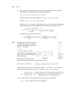
8.81 Choose an axis perpendicular to the page and passing
through the center of the cylinder. Then, applying Στ = Iα to the
cylinder gives
( 2
⎜
⎛⎝ )⋅ =t 1
2
1
2
T R M R2 M R2
a
R
⎞⎠ ⎟
=⎛⎝ ⎜
⎞⎠ ⎟
⎛⎝ ⎜
⎞⎠ ⎟
= 1
4
α , or T Mat
[1]
Now apply ΣF ma y y = to the falling objects to obtain
T
m t = − [2]
2 2 2 m g T m at
( ) − =( ) , or a g
(a) Substituting Equation [2] into [1] yields
T
Mg M
= − T
m
⎛
⎝ ⎜
⎞
⎠ ⎟
4 4
which reduces to T
Mmg
M m
=
+ 4
(b) From Equation [2] above,
a g
m
Mmg
M m
g
Mg
M m
mg
M m t = −
+
⎛
⎝ ⎜
⎞
⎠ ⎟
= −
+
=
+
1
4 4
4
4
→T
8.82 (a) A smooth (that is, frictionless) wall cannot exert a force parallel to its surface. Thus, the only
force the vertical wall can exert on the upper end of the ladder is a horizontal normal force.
(b) Consider the free-body diagram of the ladder given at the
right. If the rotation axis is perpendicular to the page
and passing through the lower end of the ladder, the
lever arm of the normal force
n
2 that the wall exerts
on the upper end of the ladder is
d L 2 = sinθ
(c) The lever arm of the force of gravity, m
g
, acting on
the ladder is
d L L = ( 2)cosθ = ( cosθ ) 2
2
2
→T
→a
t
a
2m→g
2m
M
R
→f
1
L 4.00 m
x
q
L/2
d2
n2
n1
mpg
mg
continued on next page](https://image.slidesharecdn.com/ismchapter8-140820140722-phpapp01/85/Solucionario-Fundamentos-de-Fisica-Serway-9na-edicion-Capitulo-8-83-320.jpg)
![Rotational Equilibrium and Rotational Dynamics 453
8.84 (a) Note that the cylinder has both translational and rotational
motion. The center of gravity accelerates downward while
the cylinder rotates around the center of gravity. Thus, we
apply both the translational and the rotational forms of
Newton’s second law to the cylinder:
ΣFy = may ⇒ T − mg = m(−a)
or
T = m(g − a) [1]
Στ = Iα ⇒ − Tr = I (− a r)
For a uniform, solid cylinder, I = 1 mr
2
2 so our last result becomes
Tr
mr a
r
=
⎛
⎝ ⎜
⎞
⎠ ⎟
⎛⎝ ⎜
⎞⎠ ⎟
2
2
or a
= 2
T
m
[2]
a
r
Substituting Equation [2] into Equation [1] gives T = mg − 2T , and solving for T yields
T = mg 3 .
(b) From Equation [2] above,
a
g = = ⎛⎝ ⎜
T
m m
mg
⎞⎠ ⎟
= 2 2
3
2 3
= 2 + 2 Δ gives
(c) Considering the translational motion of the center of gravity, v v y y y 2 a y
0
vy
2
3
g
h gh = + − ⎛⎝
⎞⎠
0 2 (− ) =
4 3
Using conservation of energy with PEg = 0 at the fi nal level of the cylinder gives
( + + ) = ( + + ) or 1
KE KE PE KE KE PE t r g f t r g i
2
m v 2 + 1
I ω 2 + 0 = 0 + 0 +
mgh y 2
Since ω = v r and I = 1 mr
y2
2, this becomes 1
2
v
v
2 1
y 1
mgh y
2
2
2
2
2
m mr
r
+ ( )⎛
⎝ ⎜
⎞
⎠ ⎟
= , or
3
4
m 2 mgh y v = yielding vy = 4gh 3 .
→T
ay a
r
m→g](https://image.slidesharecdn.com/ismchapter8-140820140722-phpapp01/85/Solucionario-Fundamentos-de-Fisica-Serway-9na-edicion-Capitulo-8-85-320.jpg)
![454 Chapter 8
8 .85 Considering the shoulder joint as the pivot, the second
condition of equilibrium gives
Στ = 0 ⇒ ( ) − ( °)( ) =
2
70 cm 45 4 0 cm 0
w
Fm sin .
or
w m = ( )
F
w
( ) °
=
70
2 40 45
12 4
cm
. cm sin
.
Recall that this is the total force exerted on the arm by a set of two muscles. If we approximate
that the two muscles of this pair exert equal magnitude forces, the force exerted by each muscle is
F
F w
m w
each
muscle
= = = = ( N) = ×
2
12 4
2
6 2 6 2 750 4 6
.
. . . 103 N = 4.6 kN
8.86 Observe that since the torque opposing the rotational motion of the gymnast is constant, the work
done by nonconservative forces as the gymnast goes from position 1 to position 2 (an angular
displacement of π 2 rad) will be the same as that done while the gymnast goes from position 2
to position 3 (another angular displacement of π 2 rad).
Choose PEg = 0 at the level of the bar, and let the distance from the bar to the
center of gravity of the outstretched body be rcg. Applying the work–energy theorem,
W KE PE KE PE nc g f g i
= ( + ) − ( + ) , to the rotation from position 1 to position 2 gives
W I mgr nc ( ) = ( + ) − ( + ) 12
12
ω 2 0 0 or ( W ) = I − mgr 2
cg nc 12
12
ω 2 cg [1]
2
Now, apply the work–energy theorem to the rotation from position 2 to position 3 to obtain
W I mg r I nc ( ) = + − ( ) ⎡⎣
− ( + ) 23
ω ω 2 0 cg or W I I mgr nc ( ) = − − 23
⎤⎦
12
2 12
3
2
12
ω ω 2 cg [2]
2 12
3
2
Since the frictional torque is constant and these two segments of the motion involve equal angular
displacements, W W nc nc ( ) = ( ) 23 12. Thus, equating Equation [2] to Equation [1] gives
12
Iω − Iω − mgr = Iω 2 − mgr cg cg
2 12
3
2 12
2
2
= 2 2, or ω ω 3 2 = 2 = 2 (4.0 rad s) = 5.7 rad s .
which yields ω 2
ω 3
2
→F
shoulder
→F
m
Shoulder
joint
45°
4.0 cm
70 cm
→w
2](https://image.slidesharecdn.com/ismchapter8-140820140722-phpapp01/85/Solucionario-Fundamentos-de-Fisica-Serway-9na-edicion-Capitulo-8-86-320.jpg)
![Rotational Equilibrium and Rotational Dynamics 455
8.87 (a) Free-body diagrams for each block and the
pulley are given at the right. Observe that
the angular acceleration of the pulley will be
clockwise in direction and has been given a
negative sign. Since Στ = Iα , the positive
sense for torques and angular acceleration
must be the same (counterclockwise).
For m1: ΣF ma T mg m a y y = ⇒ − = (− ) 1 1 1 , or
T m g a 1 1 = ( − ) [1]
For m2:
ΣF ma T ma x x = ⇒ = 2 2 [2]
For the pulley: Στ = Iα ⇒ T r − T r = I (−a r) 2 1 , or
a 1 2 2 − =⎛⎝ ⎜
T T
I
r
⎞⎠ ⎟
[3]
Substitute Equations [1] and [2] into Equation [3] and solve for a to obtain
a
m g
= ( 1
2
)+ +
I r m m
1 2
or
a =
( 4 00 )( 9 80
)
( 0 500
⋅ ) ( )
. .
.
kg m s
kg m 0.300 m
2
2 2 4 00 3 00
3 12
+ +
=
. .
.
kg kg
m s2
(b) Equation [1] above gives: T1 = (4.00 kg)(9.80 m s2 − 3.12 m s2 ) = 26.7 N ,
and Equation [2] yields: T2 = (3.00 kg)(3.12 m s2 ) = 9.37 N .
a
→T
1
→T
2
→
T2
→T
1
ay a
ax a
a
r
I
r
→g
m1
m1
m2](https://image.slidesharecdn.com/ismchapter8-140820140722-phpapp01/85/Solucionario-Fundamentos-de-Fisica-Serway-9na-edicion-Capitulo-8-87-320.jpg)

This document contains a series of clicker questions related to rotational equilibrium and rotational dynamics. The questions cover topics such as rotational inertia, linear and angular acceleration, torque, mechanical advantage, and rolling without slipping. Sample solutions and discussions of common student misconceptions are provided for instructors.


![Cinematica de una_particula[1] (2)](https://cdn.slidesharecdn.com/ss_thumbnails/cinematicadeunaparticula12-110806112222-phpapp01-thumbnail.jpg?width=640&height=640&fit=bounds)