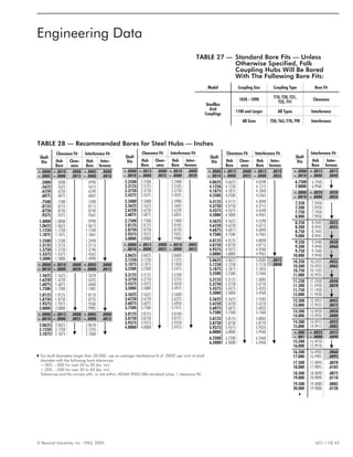
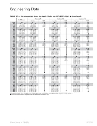
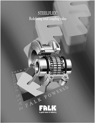
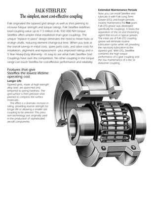
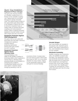
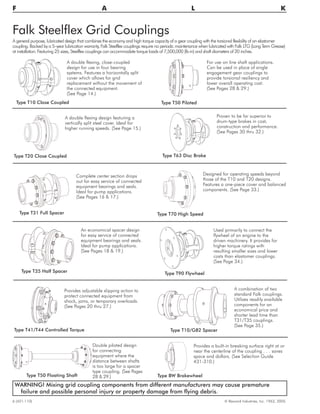
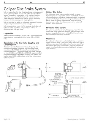
This document provides information on the Steelflex grid coupling produced by Falk. It highlights key features such as longer life through hardened and shot peened grids, extended maintenance intervals of 5 years with the use of Falk LTG grease, quick and easy replacement of just the grid component, and versatility with multiple designs available. The document includes specifications, dimensions, selection information and engineering data for Steelflex couplings.

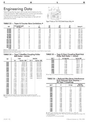
![34 (421-110) © Rexnord Industries, Inc. 1963, 2005.
F A L K
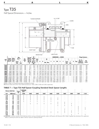
DIMENSIONS — INCHES
Adapter
CPLG
SIZE H
Assembly †
Torque
Rating
(lb-in)
Allow
Speed
rpm ‡
Max Bore
Sq Key l
Min
Bore
n
Cplg Wt
No Bore in
T Hub
lb
WR2
(lb-in2)
A B C D J L GapClutch
Dia
AF
+.000
– .005
BC G T
6.5 8.500 7.875 6-.344
.375 1050T 3500 3600 1.875 .500 18 85 5.44 5.58 2.38 2.62 3.12 3.07 .125
.375 1060T 5500 3600 2.125 .750 23 106 5.94 5.94 2.50 3.00 3.62 3.31 .125
.375 1070T 8000 3600 2.500 .750 29 130 6.38 6.94 3.00 3.44 3.75 3.81 .125
7.5 9.500 8.750 8-.344
.375 1050T 3500 3600 1.875 .500 20 115 5.44 5.58 2.38 2.62 3.12 3.07 .125
.375 1060T 5500 3600 2.125 .750 24 136 5.94 5.94 2.50 3.00 3.62 3.31 .125
.375 1070T 8000 3600 2.500 .750 30 160 6.38 6.94 3.00 3.44 3.75 3.81 .125
8 10.375 9.625 6-.406
.375 1050T 3500 3600 1.875 .500 21 151 5.44 5.58 2.38 2.62 3.12 3.07 .125
.375 1060T 5500 3600 2.125 .750 26 172 5.94 5.94 2.50 3.00 3.62 3.31 .125
.375 1070T 8000 3600 2.500 .750 32 196 6.38 6.94 3.00 3.44 3.75 3.81 .125
.500 1080T 16500 3600 3.000 1.062 48 332 7.62 8.07 3.50 4.12 4.56 4.44 .125
10 12.375 11.625 8-.406 .500 1080T 16500 3600 3.000 1.062 53 494 7.62 8.07 3.50 4.12 4.56 4.44 .125
11.5 13.875 13.125 8-.406 .500 1090T 30000 3600 3.500 1.062 74 820 8.38 8.95 3.88 4.88 4.81 4.94 .125
14 18.375 17.250 8-.531
.650 1100T 50500 2440 4.000 1.625 133 2702 9.88 10.90 4.75 5.59 6.12 5.96 .188
.750 1110T 75000 2250 4.500 1.625 162 3297 10.62 11.50 5.00 6.31 6.36 6.31 .188
16 20.375 19.250 8-.531
.650 1100T 50500 2440 4.000 1.625 145 3750 9.88 10.90 4.75 5.59 6.12 5.96 .188
.750 1110T 75000 2250 4.500 1.625 175 4507 10.62 11.50 5.00 6.31 6.36 6.31 .188
18 22.500 21.375 6-.656
.750 1110T 75000 2250 4.500 1.625 190 6243 10.62 11.50 5.00 6.31 6.36 6.31 .188
.750 1120T 110000 2025 5.000 2.375 243 7165 12.12 13.43 5.88 7.06 7.54 7.30 .250
.900 1130T 160000 1800 6.000 2.625 331 9737 13.62 14.69 6.38 8.56 7.68 8.06 .250
21 26.500 25.250 12-.656
.900 1130T 160000 1800 6.000 2.625 371 15560 13.62 14.69 6.38 8.56 7.68 8.06 .250
1.000 1140T 230000 1650 7.250 Q 2.625 478 19609 15.12 16.53 7.25 10.00 7.92 9.03 .250
1.000 1150T 320000 1500 8.000 Q 4.250 608 25878 17.84 16.56 7.20 10.60 10.68 9.11 .250
24 28.875 27.250 12-.812
.900 1130T 160000 1800 6.000 2.625 397 20463 13.62 14.69 6.38 8.56 7.68 8.06 .250
1.000 1140T 230000 1650 7.250 Q 2.625 507 25058 15.12 16.53 7.25 10.00 7.92 9.03 .250
1.000 1150T 320000 1500 8.000 Q 4.250 638 31353 17.84 16.56 7.20 10.60 10.69 9.11 .250
Machined as Required 1.000 1160T 450000 1350 9.000 Q 4.750 656 s . . . 19.76 17.85 7.80 12.00 10.96 9.80 .250
1.250 1170T 600000 1225 10.000 Q 5.250 902 s . . . 22.32 19.50 8.50 14.00 12.10 10.75 .250
H See Page 5 for General Information and Reference Notes.
Q Maximum bore is for hub with keyway for rectangular key.
s For total coupling weight add [ .2223 x (AF2
- U2
) x T ] to value shown. Size 1160 U = 15.50, Size 1170 U = 17.25.
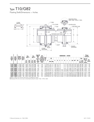
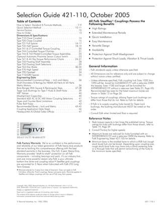
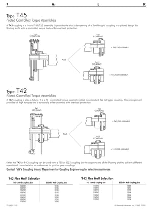
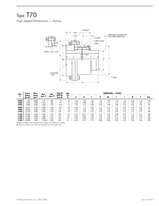
Type T90
Engine Flywheel Adapter/Dimensions — Inches
G - (NO. & SIZE OF HOLES)
ADAPTER BOLTED AND
DOWELED TO HUB BY FALK
ADAPTER
LUBE
PLUGS
COVER
GRID
T-HUB
GAP
J
D
A
C
B
L
BC
AF
T
U
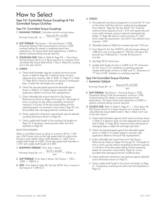
Used primarily to connect the flywheel of an
engine to the driven machinery. Adapter plates
are designed to accommodate standard SAE
J620 bolt patterns. The T90 design provides for
higher torque ratings with resulting smaller sizes
and lower costs than elastomer coupling designs.
The flexible gridmember provides torsional
damping in addition to accepting misalignment.
Adapter plates are bolted and doweled to the
hub to provide a secure joint.
Selection — Determine the proper Steelflex
coupling size using the selection method. Check
size selected against those shown in table below
for the clutch size used on the engine flywheel. If
the coupling size is not shown, refer all details to
Falk.](https://image.slidesharecdn.com/421110-140707123607-phpapp02/85/421110-34-320.jpg)