
Recommended
More Related Content
What's hot
What's hot (19)
Viewers also liked
Viewers also liked (10)
Similar to 1988 tosio a new sugar mill
Similar to 1988 tosio a new sugar mill (10)
Recently uploaded
Recently uploaded (20)
1988 tosio a new sugar mill
- 1. Proceedings of TheSouth African Sugar Technologists' Association - June 1988 A NEW SUGAR MILL DRIVE COUPLING By C. T. TOSIO Dorstener Africa (Pty) Ltd, POBox 456, Cramerview 2060 Horizontal link FIGURE 1 Originally called a "Universal Coupling", it is currently referred to as a "Multi-Misalignment" Coupling. To understand the principle of the design, it is best to consider the coupling in stationary mode. Torque is first transmitted from the driving yoke to the diagonal "compression" plate by means of the two hori- zontal parallel links. The articulation of these links permits vertical or "Y-Y" axis displacement between the driving yoke and the compression plate. The second or vertical set of links in tum transfers torque from the compression plate to the driven yoke, and their articulation similarly allows '.'X-X" axis or horizontal dis- placement. The incorporation of spherical-plain bearings in all the connecting links also permits axial end-float or "Z-Z" axis misalignment. The actual misalignment capability of the couplings in- stalled in 1974 is some 150 mm axial displacement, 5' of angular misalignment, and 100mm of end-float, all simul- taneously, which far exceeds the requirements of the installation. We now tum our attention to the coupling under review, already known as the "Multi-Misalignment Coupling MK II" or "Rope Coupling". New Design When the author left the sugar industry in 1986, he re- quested and wasgranted permission by Tongaat-Hulett Sugar to commercially exploit the design of the coupling. A mill- drive coupling was designed along the same lines as the original Amatikulu couplings, but pricing the various com- ponents indicated that the coupling would be too expensive to sell. Thoughts about ways to reduce costs by eliminating the expensive pins and bearings from the design led to a totally new design, using steel ropes as tension members between driving and driven yokes. The coupling design is as shown in Figure 2 below: The main components of the coupling are:- (i) Driving and driven yokes (ii) Two pairs of steel ropes that transfer the torque (iii) A "compression" plate that "bends" the ropes into a double-parallel-link arrangement. These formations impart to the coupling the multi-misalignment char- acteristics of the link coupling. Other features of the coupling are:- (iv) A set of reversing ropes for barring the mill to clear a choke or do maintenance welding on stop days. (v) A gearbox-shaftextensionas a safetyfeatureand a means of support for the compression plate when the coupling is not driving, and (vi) Forward driving stops for driving without the ropes or compression plate installed. It should be pointed out that the viability of the rope coupling rests on the fact that sugar mill couplings are es- sentially uni-directional and require only modest misalign- ment capacity of some 60 mm axial displacement and less than I' of angular misalignment. Vertical link Driven yoke Abstract Following twelve years of successfuloperation of the two Amatikulu Diffuser Drive Couplings, a new and less costly version has been designed specifically for Sugar Mill Drives. The paper discusses the design features, technical aspects and results to date. Introduction The problems associated with conventional "tail-bar and collar" drive couplings are familiar to all sugar engineering staff, particularly those operating the larger mills which are now the rule rather than the exception in South African factories. This new design was developed specifically to eliminate these problems. Concept The conceptual development of the new design has its origins in 1973 when Huletts Sugar Corporation were em- barking on their ambitious diffuser expansion project at Amatikulu. The author of this paper was fortunate to be employed in the Technical Management Department at the time, and to be involved in the design of the diffuser head- shaft drive couplings. The peculiar requirement of the coupling design was not .. just the high torque of2 075 kN-m, but the ability to absorb end-float due to the anticipated thermal expansion of some ten millimetres, without generating excessive axial thrust. No commercially available couplings at that time could guarantee less than the maximum axial load that the head- shaft and final-drive bearings could withstand. The design arrived at and installed consisted of a very simple link arrangement as shown in Fig. (1) below. All bearings and links are co-planar Compression plate (Sandwich Construction) ....---~ Spherical plain bearings on all pin 70
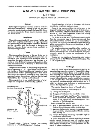
- 2. Proceedings of The South African Sugar Technologists' Association - June 1988 Rotation '_330 )"1 y Typ. for 84" mill v/,--"'_--'-_ _Taper keys see elev'n ( Hub lengths variable to suit /.. / ~( shaft to shaft dimension _.,-/ 400 I400 _ _____________ Rigid half couplings on mill and gearbox shafts 1 ...1tJ I/) Q) c- o a: Ul ...o 8o N .6Flange bolts 7~ ¢ on 1067 p.c.d. _.~ y Elevation Section y-y FIGURE 2 An interesting point is that cost-savings were not as much as anticipated, only about 15%; but the design is "low-tech" and simpler to dismantle. Practical Application The first order for a rope coupling was received from a South African Sugar Mill for the 1987/88 season. The coupling was installed on the pressure-fed final mill of a seven mill 2 134 mm tandem, handling up to fifty tons of fibre per hour, and achieving very creditable milling re- sults. The mill is of the Australian Walker design and was originally fitted with discharge hydraulics only. The instal- lation of the coupling made it possible to fit top-roll hy- draulics as well, thereby affording a measure of over-stress relief. It was hoped that this combination of coupling and top-roll hydraulics would reduce the incidence of top-roll breakages, which had been a problem for many seasons. Results After one full season of operation, the decision to install the coupling would appear to have been vindicated, as no further rolls have been broken. Post-season ultrasonic tests on the shaft have revealed no cracks. Adapting thecoupling to different situations One of the inevitable questions that arises is related to the method of adapting the coupling to suit different in- stallations. These can be divided into four groups as follows (Refer to Figure 2):- (i) For new installations: It is envisaged that the final-drive gearbox would be much closer to the mill than with conventional cou- plings,and ideallythe yokes would be taper-shrunk onto the shafts for ease of mounting and dismounting. Al- ternatively, both shafts could be fitted with rigid half- couplings, and the coupling bolted between them. (ii) Existing installations with short tail-bars (L ~ 1400mm): As in the case ofthe first installation, where the tail- bar was only 1 190mm long, one hub would be square- bored and fitted solidly to the roll shaft with four large keys, while the other would be pilot- bored and bolted onto the gearbox shaft by means of a rigid half-coupling. (iii) Existing installations - with medium-length tail-bars (l 400 <L ~ 2 220): Both hubs would be pilot-bored and bolted onto rigid half-couplings fitted on gearbox and mill shafts. The length ofthe yoke hubs would be made to suit the shaft- to-shaft gap. (iv) Existinginstallations with extra-longtailbars (L > 2 200): Here, it is envisaged that a longergearbox shaft would be installed or the existing one extended with a rigid coupling and stubshaft, and an extra support bearing be installed closer to the mill. Both hubs would be fitted directly to the shafts. Two other questions that arise relate to the anticipated life of the steel ropes and whether or not the coupling gen- erates any radial load under misaligned conditions. Before discussing these topics, it is useful to consider the factors that influence them when applied to sugar mills. (i) If the shafts are perfectly aligned, the ropes do not flex and therefore have a theoretical infinite life. The coupling generates no radial load other than its own mass acting on the shafts. (ii) Sugar-mill top-rolls are capable of journal misalign- ment up to 32 mm, but under good operating condi- tions would seldom be more than 10 mm misaligned. This misalignment can only be in the vertical plane, and it is only when the mill roll is misaligned sloping upward towards the gearbox that the radial load gen- erated adds to the bending stresses in the shaft. 71
- 3. Proceedings of TheSouth African Sugar Technologists' Association - June 1988 T, ' I T I , ,, T , , , 86,16' (2 X a) , ---tt----...--->l--'-''~,_Ttt T 2 _ _ -. ,·r FIGURE 4 Radial load generated by the coupling It is inevitable that the coupling will tend to centralise the shafts that are misaligned. In order to calculate the radial loads generated, it is best to consider the external forces acting on the compression plate. As it is a free-floating body, it can be assumed that all these forces are balanced. Consider the diagram of forces shown in Figure 4: Considering the "worst" condition for the coupling in- stalled, namely 1,5 MN-m and 40,23 mm of misalignment, the ropes would flex 20,115 mm, equating an angle of 1,92'. Under this worst condition, the one pair of ropes closes down to an angle of 86,16' (2 X a) around one end of the compression plate, while the other set opens up to an angle of 93,84' (2 X f3) around the other end. But TI Cos a = T2 Cos f3 . Cos 46,92' .. T I = T2 X Cos 43,08' = T2 X 0,935 In the coupling installed T = 750 kN at maximum torque and for small angles of deflection, TI + T2 = 1 500 kN. .. TI = 725 kN and T2 = 775 kN The nett vertical load imposed on the yokes of the cou- pling is therefore T2 - TI = 50 kN, or 5 metric tons force. As the radial loads are proportional to angle of flexure and torque, for the 'normal' condition of operating, the ra- dial load would reduce to 16 kN, or approximately 1 kN force per mm of misalignment at the centre-line of the coupling. It can be seen that the order of magnitude of generated radial loads is relatively low, and would therefore have only a minor effect on the bending stresses already present in the shaft under milling conditions. Advantages of the 'Rope' Coupling The technical advantages ofthe coupling can be discussed by considering the problems that it eliminates. (i) Maintenance - The only maintenance required is a quarterly rotation of the ropes. There is no offcrop maintenance to 'squares as the hubs are keyed on solidly and do not fret. Pre-tensile stress in the rope would be some 17,2%. The graph shows that for the worst case, the predicted life would be 7,5 X 10⁶ cycles, which is equivalent to ± 38 months of operation. It also shows for a normal case, life would be ± 33 X 106 cycles, or some 170 months of operation. These figures are based on 5 RPM 27 days per month operation. In addition, the rope fixings are designed for periodic (quarterly) 120' rotation. This theoretically trebles the life of the ropes, but its main purpose would be to establish if any wires had broken; and plan for timeous replacement. (iii) While most drives for 2 134 mm mills can apply a stall- ing-torque of 1,5 MN-m, it would be fair to assume a normal driving torque in the 1,1-1,2 MN-m range. (iv) The rope coupling design is such that the ropes flex half the amount ofoff-set or misalignment. The length over which the ropes flex is 600 mm. We should therefore discuss these questions assuming both worst and normal driving conditions. Figures pertaining to the mill where the coupling was installed have been selected as being fairly typical, as well as factual. The mill hydraulics can rise 25 mm; journal centres are 3 048 mm and the centre-line of the coupling is a further I 857 mm from the pinion journal centreline. These dimensions dictate that the coupling has to absorb a maximum of 24 X 1,61 = 40,23 mm misalignment. The worst and normaldriving conditions for the cou- pling as installed are therefore:- 1,5 MN-m torque at 40,23 mm misalignment, and; 1,2 MN-m on torque at 16 mm misalignment Anticipated life of the ropes The life of a steel rope is directly dependent on angle of deflection, cycles per minute and safety factor. Before the final rope size was selected, the manufacturers conducted exhaustive fatigue tests to determine the anticipated life of the ropes under various conditions. A steel rope is consid- ered discardable when only ten visible wires have failed within a length of six rope diameters. The following graph (Figure 3) shows predicted life in cycles plotted against load for I', 1,5' and 3' of deflection for the ropes that were se- lected. These deflections equate respectively to 10, 16 and 31 millimetres of deflection in the rope or 21, 31 and 63 millimetres of shaft misalignment at the centre-line of the coupling. The actual angles of flex are 1,9' and 0,75' for "worst" and "normal" conditions respectively and their po- sitions shown on the graph are approximate. H::[l[i~tR'~~;;)f Ii 10~l:il{r-=,.·,_!·1 r~Ej~~'2cD 55 . "~'__ . .... . ._ I .~~~ 3°I '0 - a: ~ I I Q) 5' , - -- -" i - -,'- ,-- - ..--- 0- . 106 107 108 Number of fatigue cycles to ten broken wires FIGURE 3 Pre-tensile stress level versus number of fatigue cycles to ten broken wires 72
- 4. Proceedings of The SouthAfrican Sugar Technologists' Association - June 1988 (ii) No thrust between mill and gearbox - The coupling is incapable of generating axial thrust. Even in the event of a transverse shaft-break, the coupling ropes would merely come out of their grooves in the yokes and compression plate. Mill and final-drive bearinglifemust be greatly improved. (iii) No seizure - The coupling cannot seize up and apply unquantifiable bending moments to the mill-roll shaft. This is considered to be a major contributing factor in the breaking of mill-roll shafts. In the rope coupling, these loads are quantified and the additional bending stresses in the shaft can therefore easily be calculated. The major advantage therefore is in the increased life of mill-roll shafts. Disadvantages of the coupling The only disadvantages of the coupling are: (i) Radial swing - The coupling installed is 2,7 m across comers and in most installations would require guard- ing to prevent injury to personnel. 73 (ii) Cost - Current costs are roughly twice that of a con- ventional coupling, depending on the method of fixing to the shafts. It should be pointed out here that in the caseof a new tandem installation, these extra costswould be more than offsetby savings on mill-house and foun- dation costs. Conclusions To date, the coupling has achieved everything it was de- signed to do, and only time will confirm or disprove the anticipated life claims. Acknowledgements Thanks are due to the Umfolozi Co-operative Sugar- Planters mill staff, for providing the opportunity of proving the concept; to Haggie Rand Limited for their assistance in testing and designing the ropes; to Escogear (Pty) Limited, for their support and encouragement during the project; and to the Sugar Milling Research Institute for their assistance in supplying useful information.