SlideShare a Scribd company logo
Propeller modifications
                                                 Trailing edge adjustment for heavy running propellers


One propeller modification that Wärtsilä carries out is          power can be generated at full rpm in service conditions
the trailing edge adjustment to cure “heavy running”            (including the sea margin).
propellers.                                                       The engine loading diagram for a heavy running propeller
  “Heavy running” means that power generation by                is shown in Figure 2. For some reason, the propeller’s power
the propeller no longer matches the performance of the          absorption in trial conditions may show only a small or even
engine. Because of this, the engine operates in an overload     a non-existent sea margin. If the ship’s resistance increases
condition at inadequate rpm. This leads to high exhaust         now, the engine will run in overload. At low propeller speeds,
gas temperatures as well as increased wear of pistons, liners   the power demand is larger than the engine can deliver; the
and valves, resulting in high maintenance costs. It may         propeller’s power curve crosses the engine load limit before
also be impossible to maintain the vessel’s operational         the full power of the engine is reached.
speed, which may cause problems with schedules.
  Figure 1 shows the engine loading diagram for a regular
situation. The propeller’s pitch is selected so that 85 %
of the MCR power is generated at 100 % nominal shaft
speed. This creates a sea margin to accommodate any
increase in the ship’s resistance due to the weather. Full
Fig. 1 The engine loading diagram in a regular situation.


A propeller can become “heavy running” due to:                  Diameter cropping is effective but not recommended
  Fouling of the hull and propeller                             since it results in a two or three per cent loss in efficiency.
  Ageing of the engine                                          Today the most sophisticated way to cure a heavy running
  Incorrect design of the propeller (pitch is too high)         propeller is a trailing edge adjustment.
  Modification of the ship (length and/or draught of               Figure 3 shows a sketch of the modified trailing edge.
  ship increased)                                               The pitch angle of a profile section is defined by the
  Change in normal operating profile and/or loading              line through the nose and tail of the propeller section.
  conditions.                                                   The trailing edge is cut off at a certain length, in order
Basically there is a mismatch between the propeller curve       to reprofile the section. The new tail is raised above
and the engine limit. Modifying the propeller’s pitch can       the original nose-tail line, decreasing the pitch angle. A
improve interaction between propeller and engine.               hydrodynamic profile is grinded to assure that the wing
                                                                section works properly and to avoid erosive cavitation. In
Working principle                                               addition, an anti-singing edge is incorporated to avoid
It is necessary to raise the operating point of the propeller   unwanted inboard noise. A major benefit of the trailing
to a higher shaft speed, so as to bring the engine out of the   edge adjustment is that there is no loss in efficiency.
overload area.                                                    In principle, a propeller can be modified up to a
  A decrease in pitch will result in a higher shaft speed       maximum of seven per cent in the propeller’s rotational
with the same engine power.                                     speed. In most cases this is sufficient to restore good
  Up until 10 years ago, a propeller was repitched either       interaction between propeller and engine.
by twisting the blade or by diameter cropping. Twisting
the blade is inaccurate and cannot be carried out on site.
Fig. 2 The engine loading diagram for a heavy running propeller.


Propeller modification calculations                                 A modification calculation includes:
Working closely with the owner of the vessel we first                 Engineering
determine the current performance of the propeller and               Modification drawings of propeller
the engine. We then define the required new performance               A report
and increase in rpm. We carry out detailed hydrodynamic              Template drawings
calculations for power absorption, cavitation, efficiency,            One set of steel templates.
pressure pulses and strength. These analyses can be made           If we receive the order to carry out the modification, the
both for Lips propellers and for third party designs. We           costs for the modification calculation will be deducted
produce a report for the customer, and after approval the          from the total costs. Engineering of the trailing edge
designed trailing edge modification can be made.                    adjustment can be carried out within one week.


The following information is required:
  Propeller drawing, including profile section drawings in
  case of third party design
  Engine diagram
  Current performance of propeller (power-rpm-ship
  speed)
  Expectations of the owner after modification of the
  fixed pitch propeller.

                                                                   Fig. 3 A sketch of the modified trailing edge.
Where can propeller modifications
be performed?
The propeller can be modified while the propeller is fitted
on the shaft, there is no need to demount the propeller.
This means the cutting and grinding can be carried out
at ship repair yards, in dry dock or at the pier side at
trimmed position. The work can even be carried out
offshore, depending on the weather conditions. We have
a global service network of engineers trained to perform
propeller modifications in order to serve locally and keep
the costs as low as possible.


Summary
A propeller is “heavy running” if the propeller curve
no longer matches engine performance. Repitching the
propeller can restore good interaction between propeller
and engine. A decrease in pitch will result in the desired                      Checking modified trailing edge profile section
higher rpm for the propeller.                                                   by means of templates.

   A trailing edge adjustment can decrease the mean pitch
of the propeller. Dedicated hydrodynamic analyses are
made while designing the modification.
   This sort of pitch correction is usually carried out on
site, at ship repair yards, at pier side etc.
   We have executed over 150 designs and modifications
in the following operational area.
   Wärtsilä Lips design – third party design
   Diameter ranging from 2.0 m up to 8.5 m
   Rpm corrections from 2% to 7%
   Ship speeds from 10 knots to 25 knots.                                       Equal pieces of propeller material are cut off.


                                                                                Trailing edge adjustment at pier side.
WÄRTSILÄ®   is a registered trademark. Copyright © 2006 Wärtsilä Corporation.


Wärtsilä Propulsion Netherlands B.V.
Lipsstraat 52, P.O. Box 6                      Tel. +31 416 388115
5150 BB Drunen                                 Fax +31 416 373162
The Netherlands                                www.wartsila.com

More Related Content

What's hot

IRJET- Design and Steady-State Thermal Analysis of Disc Brake
IRJET-  	  Design and Steady-State Thermal Analysis of Disc BrakeIRJET-  	  Design and Steady-State Thermal Analysis of Disc Brake
IRJET- Design and Steady-State Thermal Analysis of Disc BrakeIRJET Journal
 
FORCE CALCULATION IN UPRIGHT OF A FSAE RACE CAR
FORCE CALCULATION IN UPRIGHT OF A FSAE RACE CARFORCE CALCULATION IN UPRIGHT OF A FSAE RACE CAR
FORCE CALCULATION IN UPRIGHT OF A FSAE RACE CARIAEME Publication
 
Yaw stability of single versus tandem axle tractors
Yaw stability of single versus tandem axle tractorsYaw stability of single versus tandem axle tractors
Yaw stability of single versus tandem axle tractorsRoberto Davis
 
new trends in aerodynamics
new trends in aerodynamicsnew trends in aerodynamics
new trends in aerodynamicsSurinder Tiwari
 
Resume_Pranat Mishra
Resume_Pranat MishraResume_Pranat Mishra
Resume_Pranat Mishrapranat mishra
 
Design and Analysis of Crankshaft for Internal Combustion Engine
Design and Analysis of Crankshaft for Internal Combustion EngineDesign and Analysis of Crankshaft for Internal Combustion Engine
Design and Analysis of Crankshaft for Internal Combustion Engineijtsrd
 
Design of half shaft and wheel hub assembly for racing car
Design of half shaft and wheel hub assembly for racing carDesign of half shaft and wheel hub assembly for racing car
Design of half shaft and wheel hub assembly for racing carRavi Shekhar
 
NMSU_Design_Report_2016
NMSU_Design_Report_2016NMSU_Design_Report_2016
NMSU_Design_Report_2016Arthur Cox
 
OSA-10-Design_Improvement_in_Kingpin_Sonalika(ITL)
OSA-10-Design_Improvement_in_Kingpin_Sonalika(ITL)OSA-10-Design_Improvement_in_Kingpin_Sonalika(ITL)
OSA-10-Design_Improvement_in_Kingpin_Sonalika(ITL)YASEEN KHAN
 
Design, Analysis and Optimization of Automobile Wheel Hub
Design, Analysis and Optimization of Automobile Wheel HubDesign, Analysis and Optimization of Automobile Wheel Hub
Design, Analysis and Optimization of Automobile Wheel HubKrishna Khandelwal
 
SU Compliant Morphing Overview 2
SU Compliant Morphing Overview 2SU Compliant Morphing Overview 2
SU Compliant Morphing Overview 2Benjamin Woods
 
Design and build portable hydraulic lifting platform for heavy vehicles
Design and build portable hydraulic lifting platform for heavy vehiclesDesign and build portable hydraulic lifting platform for heavy vehicles
Design and build portable hydraulic lifting platform for heavy vehiclesjunaidbuttar
 
Design of an Engine Crankshaft
Design of an Engine CrankshaftDesign of an Engine Crankshaft
Design of an Engine Crankshaftsarkersakib
 
GEOMETRIC OPTIMIZATION OF CRANK SHAFT FOR OPTIMUM DESIGN AND IMPROVEMENT OF LIFE
GEOMETRIC OPTIMIZATION OF CRANK SHAFT FOR OPTIMUM DESIGN AND IMPROVEMENT OF LIFEGEOMETRIC OPTIMIZATION OF CRANK SHAFT FOR OPTIMUM DESIGN AND IMPROVEMENT OF LIFE
GEOMETRIC OPTIMIZATION OF CRANK SHAFT FOR OPTIMUM DESIGN AND IMPROVEMENT OF LIFEIjripublishers Ijri
 
Geometric design of the track
Geometric design of the trackGeometric design of the track
Geometric design of the trackT.Naga Anusha
 
15 lecture ppt
15 lecture ppt15 lecture ppt
15 lecture pptmiladshah
 
design and analysis of multi leaf spring ppt
 design and analysis of multi leaf spring ppt design and analysis of multi leaf spring ppt
design and analysis of multi leaf spring pptVenugopalraoSuravara
 

What's hot (20)

IRJET- Design and Steady-State Thermal Analysis of Disc Brake
IRJET-  	  Design and Steady-State Thermal Analysis of Disc BrakeIRJET-  	  Design and Steady-State Thermal Analysis of Disc Brake
IRJET- Design and Steady-State Thermal Analysis of Disc Brake
 
DESIGN OPTIMIZATION OF WIND TURBINE BLADE
DESIGN OPTIMIZATION OF WIND TURBINE BLADEDESIGN OPTIMIZATION OF WIND TURBINE BLADE
DESIGN OPTIMIZATION OF WIND TURBINE BLADE
 
smsr
smsrsmsr
smsr
 
FORCE CALCULATION IN UPRIGHT OF A FSAE RACE CAR
FORCE CALCULATION IN UPRIGHT OF A FSAE RACE CARFORCE CALCULATION IN UPRIGHT OF A FSAE RACE CAR
FORCE CALCULATION IN UPRIGHT OF A FSAE RACE CAR
 
Yaw stability of single versus tandem axle tractors
Yaw stability of single versus tandem axle tractorsYaw stability of single versus tandem axle tractors
Yaw stability of single versus tandem axle tractors
 
new trends in aerodynamics
new trends in aerodynamicsnew trends in aerodynamics
new trends in aerodynamics
 
Resume_Pranat Mishra
Resume_Pranat MishraResume_Pranat Mishra
Resume_Pranat Mishra
 
Design and Analysis of Crankshaft for Internal Combustion Engine
Design and Analysis of Crankshaft for Internal Combustion EngineDesign and Analysis of Crankshaft for Internal Combustion Engine
Design and Analysis of Crankshaft for Internal Combustion Engine
 
Design of half shaft and wheel hub assembly for racing car
Design of half shaft and wheel hub assembly for racing carDesign of half shaft and wheel hub assembly for racing car
Design of half shaft and wheel hub assembly for racing car
 
NMSU_Design_Report_2016
NMSU_Design_Report_2016NMSU_Design_Report_2016
NMSU_Design_Report_2016
 
OSA-10-Design_Improvement_in_Kingpin_Sonalika(ITL)
OSA-10-Design_Improvement_in_Kingpin_Sonalika(ITL)OSA-10-Design_Improvement_in_Kingpin_Sonalika(ITL)
OSA-10-Design_Improvement_in_Kingpin_Sonalika(ITL)
 
Design, Analysis and Optimization of Automobile Wheel Hub
Design, Analysis and Optimization of Automobile Wheel HubDesign, Analysis and Optimization of Automobile Wheel Hub
Design, Analysis and Optimization of Automobile Wheel Hub
 
Energy in wind
Energy in windEnergy in wind
Energy in wind
 
SU Compliant Morphing Overview 2
SU Compliant Morphing Overview 2SU Compliant Morphing Overview 2
SU Compliant Morphing Overview 2
 
Design and build portable hydraulic lifting platform for heavy vehicles
Design and build portable hydraulic lifting platform for heavy vehiclesDesign and build portable hydraulic lifting platform for heavy vehicles
Design and build portable hydraulic lifting platform for heavy vehicles
 
Design of an Engine Crankshaft
Design of an Engine CrankshaftDesign of an Engine Crankshaft
Design of an Engine Crankshaft
 
GEOMETRIC OPTIMIZATION OF CRANK SHAFT FOR OPTIMUM DESIGN AND IMPROVEMENT OF LIFE
GEOMETRIC OPTIMIZATION OF CRANK SHAFT FOR OPTIMUM DESIGN AND IMPROVEMENT OF LIFEGEOMETRIC OPTIMIZATION OF CRANK SHAFT FOR OPTIMUM DESIGN AND IMPROVEMENT OF LIFE
GEOMETRIC OPTIMIZATION OF CRANK SHAFT FOR OPTIMUM DESIGN AND IMPROVEMENT OF LIFE
 
Geometric design of the track
Geometric design of the trackGeometric design of the track
Geometric design of the track
 
15 lecture ppt
15 lecture ppt15 lecture ppt
15 lecture ppt
 
design and analysis of multi leaf spring ppt
 design and analysis of multi leaf spring ppt design and analysis of multi leaf spring ppt
design and analysis of multi leaf spring ppt
 

Viewers also liked

COMPARISON OF ALUMINUM & COMPOSITE MATERIALS FOR SHIP PROPELLER USING FEA
COMPARISON OF ALUMINUM & COMPOSITE MATERIALS FOR SHIP PROPELLER USING FEACOMPARISON OF ALUMINUM & COMPOSITE MATERIALS FOR SHIP PROPELLER USING FEA
COMPARISON OF ALUMINUM & COMPOSITE MATERIALS FOR SHIP PROPELLER USING FEAIjripublishers Ijri
 
Lect 9 ship propellers (new)
Lect 9 ship propellers (new)Lect 9 ship propellers (new)
Lect 9 ship propellers (new)Saif Alenzi
 
Propeller making process finnscrew
Propeller making process   finnscrewPropeller making process   finnscrew
Propeller making process finnscrewMohd Syahmi Nuruddin
 
Cavitation in PUMP & NPSH detailed (FLUID machinery, centrifugal pumps, recip...
Cavitation in PUMP & NPSH detailed (FLUID machinery, centrifugal pumps, recip...Cavitation in PUMP & NPSH detailed (FLUID machinery, centrifugal pumps, recip...
Cavitation in PUMP & NPSH detailed (FLUID machinery, centrifugal pumps, recip...Jeet Amrutiya
 
Cavitation in pumps and ...
Cavitation in pumps and ...Cavitation in pumps and ...
Cavitation in pumps and ...siavosh_84
 
NPSH and pump cavitation
NPSH and pump cavitationNPSH and pump cavitation
NPSH and pump cavitationBrian Gongol
 
Propeller and Rudder
Propeller and RudderPropeller and Rudder
Propeller and Rudderberkayerd
 

Viewers also liked (9)

COMPARISON OF ALUMINUM & COMPOSITE MATERIALS FOR SHIP PROPELLER USING FEA
COMPARISON OF ALUMINUM & COMPOSITE MATERIALS FOR SHIP PROPELLER USING FEACOMPARISON OF ALUMINUM & COMPOSITE MATERIALS FOR SHIP PROPELLER USING FEA
COMPARISON OF ALUMINUM & COMPOSITE MATERIALS FOR SHIP PROPELLER USING FEA
 
Lect 9 ship propellers (new)
Lect 9 ship propellers (new)Lect 9 ship propellers (new)
Lect 9 ship propellers (new)
 
Propeller making process finnscrew
Propeller making process   finnscrewPropeller making process   finnscrew
Propeller making process finnscrew
 
Basics of-ship-resistance
Basics of-ship-resistanceBasics of-ship-resistance
Basics of-ship-resistance
 
Cavitation in PUMP & NPSH detailed (FLUID machinery, centrifugal pumps, recip...
Cavitation in PUMP & NPSH detailed (FLUID machinery, centrifugal pumps, recip...Cavitation in PUMP & NPSH detailed (FLUID machinery, centrifugal pumps, recip...
Cavitation in PUMP & NPSH detailed (FLUID machinery, centrifugal pumps, recip...
 
Cavitation in pumps and ...
Cavitation in pumps and ...Cavitation in pumps and ...
Cavitation in pumps and ...
 
NPSH and pump cavitation
NPSH and pump cavitationNPSH and pump cavitation
NPSH and pump cavitation
 
SHIP TYPES INFORMATION
SHIP TYPES INFORMATIONSHIP TYPES INFORMATION
SHIP TYPES INFORMATION
 
Propeller and Rudder
Propeller and RudderPropeller and Rudder
Propeller and Rudder
 

Similar to Propeller modifications product_leaflet

CPP-Propulsors-ESD (1)_101528.pdf
CPP-Propulsors-ESD (1)_101528.pdfCPP-Propulsors-ESD (1)_101528.pdf
CPP-Propulsors-ESD (1)_101528.pdfRohitKumar234819
 
IRJET- Optimized Blade Replacement Solution in Wind Turbine using Craneless T...
IRJET- Optimized Blade Replacement Solution in Wind Turbine using Craneless T...IRJET- Optimized Blade Replacement Solution in Wind Turbine using Craneless T...
IRJET- Optimized Blade Replacement Solution in Wind Turbine using Craneless T...IRJET Journal
 
MJP-UltraJet-Designers-Guide.pdf
MJP-UltraJet-Designers-Guide.pdfMJP-UltraJet-Designers-Guide.pdf
MJP-UltraJet-Designers-Guide.pdfsuryaman10
 
Analysis About Losses of Centrifugal Pump by Matlab
Analysis About Losses of Centrifugal Pump by MatlabAnalysis About Losses of Centrifugal Pump by Matlab
Analysis About Losses of Centrifugal Pump by Matlabijceronline
 
Design of a Light Sport Aircraft
Design of a Light Sport AircraftDesign of a Light Sport Aircraft
Design of a Light Sport AircraftNathan Butt
 
Improved power plant performance, Sulzer Technical Review, 2009
Improved power plant performance, Sulzer Technical Review, 2009Improved power plant performance, Sulzer Technical Review, 2009
Improved power plant performance, Sulzer Technical Review, 2009Shaun West
 
Propulsion Selection and Analysis for Unmanned Aerial Vehicles for SAE Aero D...
Propulsion Selection and Analysis for Unmanned Aerial Vehicles for SAE Aero D...Propulsion Selection and Analysis for Unmanned Aerial Vehicles for SAE Aero D...
Propulsion Selection and Analysis for Unmanned Aerial Vehicles for SAE Aero D...theijes
 
Marine propulsion, alternative propulsive devices.ppt
Marine propulsion, alternative propulsive devices.pptMarine propulsion, alternative propulsive devices.ppt
Marine propulsion, alternative propulsive devices.pptSaptarshiBasu23
 
200118 chapter 8 hydromechanical
200118 chapter 8 hydromechanical200118 chapter 8 hydromechanical
200118 chapter 8 hydromechanicalBinu Karki
 
Variable compression ratio engine
Variable compression ratio engineVariable compression ratio engine
Variable compression ratio enginearunanikkattu
 
The Floating Axis Wind Turbine's Preliminary Study
The Floating Axis Wind Turbine's Preliminary StudyThe Floating Axis Wind Turbine's Preliminary Study
The Floating Axis Wind Turbine's Preliminary StudyIRJET Journal
 
Design and Analysis of Spiral Wind Turbine with Various Wind Speed
Design and Analysis of Spiral Wind Turbine with Various Wind SpeedDesign and Analysis of Spiral Wind Turbine with Various Wind Speed
Design and Analysis of Spiral Wind Turbine with Various Wind SpeedIRJET Journal
 
LOM 10303 MARINE TECHNOLOGY SLIDE - SNA.pptx
LOM 10303 MARINE TECHNOLOGY SLIDE - SNA.pptxLOM 10303 MARINE TECHNOLOGY SLIDE - SNA.pptx
LOM 10303 MARINE TECHNOLOGY SLIDE - SNA.pptxSitiNurulAinAhmadTer
 
IRJET- Off-Axis Motor Overdrive Ducted Fan
IRJET- Off-Axis Motor Overdrive Ducted FanIRJET- Off-Axis Motor Overdrive Ducted Fan
IRJET- Off-Axis Motor Overdrive Ducted FanIRJET Journal
 
Mae senior design poster rev b
Mae senior design poster rev bMae senior design poster rev b
Mae senior design poster rev bLiamRamsay
 
Numerical Investigation Of Compression Performance Of Different Blade Configu...
Numerical Investigation Of Compression Performance Of Different Blade Configu...Numerical Investigation Of Compression Performance Of Different Blade Configu...
Numerical Investigation Of Compression Performance Of Different Blade Configu...IJERA Editor
 

Similar to Propeller modifications product_leaflet (20)

CPP-Propulsors-ESD (1)_101528.pdf
CPP-Propulsors-ESD (1)_101528.pdfCPP-Propulsors-ESD (1)_101528.pdf
CPP-Propulsors-ESD (1)_101528.pdf
 
IRJET- Optimized Blade Replacement Solution in Wind Turbine using Craneless T...
IRJET- Optimized Blade Replacement Solution in Wind Turbine using Craneless T...IRJET- Optimized Blade Replacement Solution in Wind Turbine using Craneless T...
IRJET- Optimized Blade Replacement Solution in Wind Turbine using Craneless T...
 
MJP-UltraJet-Designers-Guide.pdf
MJP-UltraJet-Designers-Guide.pdfMJP-UltraJet-Designers-Guide.pdf
MJP-UltraJet-Designers-Guide.pdf
 
Analysis About Losses of Centrifugal Pump by Matlab
Analysis About Losses of Centrifugal Pump by MatlabAnalysis About Losses of Centrifugal Pump by Matlab
Analysis About Losses of Centrifugal Pump by Matlab
 
I1304035459
I1304035459I1304035459
I1304035459
 
Design of a Light Sport Aircraft
Design of a Light Sport AircraftDesign of a Light Sport Aircraft
Design of a Light Sport Aircraft
 
Improved power plant performance, Sulzer Technical Review, 2009
Improved power plant performance, Sulzer Technical Review, 2009Improved power plant performance, Sulzer Technical Review, 2009
Improved power plant performance, Sulzer Technical Review, 2009
 
Propulsion Selection and Analysis for Unmanned Aerial Vehicles for SAE Aero D...
Propulsion Selection and Analysis for Unmanned Aerial Vehicles for SAE Aero D...Propulsion Selection and Analysis for Unmanned Aerial Vehicles for SAE Aero D...
Propulsion Selection and Analysis for Unmanned Aerial Vehicles for SAE Aero D...
 
Marine propulsion, alternative propulsive devices.ppt
Marine propulsion, alternative propulsive devices.pptMarine propulsion, alternative propulsive devices.ppt
Marine propulsion, alternative propulsive devices.ppt
 
Ship Rudders
Ship RuddersShip Rudders
Ship Rudders
 
200118 chapter 8 hydromechanical
200118 chapter 8 hydromechanical200118 chapter 8 hydromechanical
200118 chapter 8 hydromechanical
 
Variable compression ratio engine
Variable compression ratio engineVariable compression ratio engine
Variable compression ratio engine
 
The Floating Axis Wind Turbine's Preliminary Study
The Floating Axis Wind Turbine's Preliminary StudyThe Floating Axis Wind Turbine's Preliminary Study
The Floating Axis Wind Turbine's Preliminary Study
 
Aj34219223
Aj34219223Aj34219223
Aj34219223
 
Design and Analysis of Spiral Wind Turbine with Various Wind Speed
Design and Analysis of Spiral Wind Turbine with Various Wind SpeedDesign and Analysis of Spiral Wind Turbine with Various Wind Speed
Design and Analysis of Spiral Wind Turbine with Various Wind Speed
 
LOM 10303 MARINE TECHNOLOGY SLIDE - SNA.pptx
LOM 10303 MARINE TECHNOLOGY SLIDE - SNA.pptxLOM 10303 MARINE TECHNOLOGY SLIDE - SNA.pptx
LOM 10303 MARINE TECHNOLOGY SLIDE - SNA.pptx
 
IRJET- Off-Axis Motor Overdrive Ducted Fan
IRJET- Off-Axis Motor Overdrive Ducted FanIRJET- Off-Axis Motor Overdrive Ducted Fan
IRJET- Off-Axis Motor Overdrive Ducted Fan
 
Mae senior design poster rev b
Mae senior design poster rev bMae senior design poster rev b
Mae senior design poster rev b
 
Numerical Investigation Of Compression Performance Of Different Blade Configu...
Numerical Investigation Of Compression Performance Of Different Blade Configu...Numerical Investigation Of Compression Performance Of Different Blade Configu...
Numerical Investigation Of Compression Performance Of Different Blade Configu...
 
M505068995
M505068995M505068995
M505068995
 

Propeller modifications product_leaflet

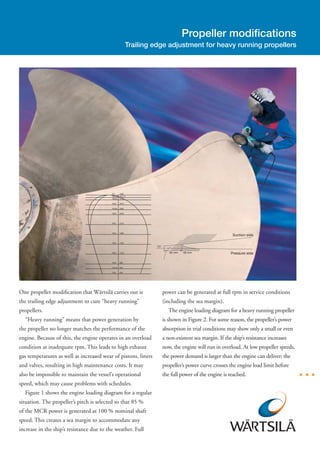
  • 1. Propeller modifications Trailing edge adjustment for heavy running propellers One propeller modification that Wärtsilä carries out is power can be generated at full rpm in service conditions the trailing edge adjustment to cure “heavy running” (including the sea margin). propellers. The engine loading diagram for a heavy running propeller “Heavy running” means that power generation by is shown in Figure 2. For some reason, the propeller’s power the propeller no longer matches the performance of the absorption in trial conditions may show only a small or even engine. Because of this, the engine operates in an overload a non-existent sea margin. If the ship’s resistance increases condition at inadequate rpm. This leads to high exhaust now, the engine will run in overload. At low propeller speeds, gas temperatures as well as increased wear of pistons, liners the power demand is larger than the engine can deliver; the and valves, resulting in high maintenance costs. It may propeller’s power curve crosses the engine load limit before also be impossible to maintain the vessel’s operational the full power of the engine is reached. speed, which may cause problems with schedules. Figure 1 shows the engine loading diagram for a regular situation. The propeller’s pitch is selected so that 85 % of the MCR power is generated at 100 % nominal shaft speed. This creates a sea margin to accommodate any increase in the ship’s resistance due to the weather. Full
  • 2. Fig. 1 The engine loading diagram in a regular situation. A propeller can become “heavy running” due to: Diameter cropping is effective but not recommended Fouling of the hull and propeller since it results in a two or three per cent loss in efficiency. Ageing of the engine Today the most sophisticated way to cure a heavy running Incorrect design of the propeller (pitch is too high) propeller is a trailing edge adjustment. Modification of the ship (length and/or draught of Figure 3 shows a sketch of the modified trailing edge. ship increased) The pitch angle of a profile section is defined by the Change in normal operating profile and/or loading line through the nose and tail of the propeller section. conditions. The trailing edge is cut off at a certain length, in order Basically there is a mismatch between the propeller curve to reprofile the section. The new tail is raised above and the engine limit. Modifying the propeller’s pitch can the original nose-tail line, decreasing the pitch angle. A improve interaction between propeller and engine. hydrodynamic profile is grinded to assure that the wing section works properly and to avoid erosive cavitation. In Working principle addition, an anti-singing edge is incorporated to avoid It is necessary to raise the operating point of the propeller unwanted inboard noise. A major benefit of the trailing to a higher shaft speed, so as to bring the engine out of the edge adjustment is that there is no loss in efficiency. overload area. In principle, a propeller can be modified up to a A decrease in pitch will result in a higher shaft speed maximum of seven per cent in the propeller’s rotational with the same engine power. speed. In most cases this is sufficient to restore good Up until 10 years ago, a propeller was repitched either interaction between propeller and engine. by twisting the blade or by diameter cropping. Twisting the blade is inaccurate and cannot be carried out on site.
  • 3. Fig. 2 The engine loading diagram for a heavy running propeller. Propeller modification calculations A modification calculation includes: Working closely with the owner of the vessel we first Engineering determine the current performance of the propeller and Modification drawings of propeller the engine. We then define the required new performance A report and increase in rpm. We carry out detailed hydrodynamic Template drawings calculations for power absorption, cavitation, efficiency, One set of steel templates. pressure pulses and strength. These analyses can be made If we receive the order to carry out the modification, the both for Lips propellers and for third party designs. We costs for the modification calculation will be deducted produce a report for the customer, and after approval the from the total costs. Engineering of the trailing edge designed trailing edge modification can be made. adjustment can be carried out within one week. The following information is required: Propeller drawing, including profile section drawings in case of third party design Engine diagram Current performance of propeller (power-rpm-ship speed) Expectations of the owner after modification of the fixed pitch propeller. Fig. 3 A sketch of the modified trailing edge.
  • 4. Where can propeller modifications be performed? The propeller can be modified while the propeller is fitted on the shaft, there is no need to demount the propeller. This means the cutting and grinding can be carried out at ship repair yards, in dry dock or at the pier side at trimmed position. The work can even be carried out offshore, depending on the weather conditions. We have a global service network of engineers trained to perform propeller modifications in order to serve locally and keep the costs as low as possible. Summary A propeller is “heavy running” if the propeller curve no longer matches engine performance. Repitching the propeller can restore good interaction between propeller and engine. A decrease in pitch will result in the desired Checking modified trailing edge profile section higher rpm for the propeller. by means of templates. A trailing edge adjustment can decrease the mean pitch of the propeller. Dedicated hydrodynamic analyses are made while designing the modification. This sort of pitch correction is usually carried out on site, at ship repair yards, at pier side etc. We have executed over 150 designs and modifications in the following operational area. Wärtsilä Lips design – third party design Diameter ranging from 2.0 m up to 8.5 m Rpm corrections from 2% to 7% Ship speeds from 10 knots to 25 knots. Equal pieces of propeller material are cut off. Trailing edge adjustment at pier side. WÄRTSILÄ® is a registered trademark. Copyright © 2006 Wärtsilä Corporation. Wärtsilä Propulsion Netherlands B.V. Lipsstraat 52, P.O. Box 6 Tel. +31 416 388115 5150 BB Drunen Fax +31 416 373162 The Netherlands www.wartsila.com