This document discusses analyzing the geometric dilution of precision (GDOP) for the Indian Regional Navigation Satellite System (IRNSS) to improve user positioning accuracy. It first provides background on IRNSS and how GDOP relates to satellite geometry and positioning accuracy. It then describes using Systems Tool Kit (STK) software to simulate IRNSS satellites over 24 hours and calculate GDOP values for optimal configurations of 4 satellites as well as all satellites in view at different times. The goal is to analyze which approach (4 satellites or all satellites) provides better user positioning accuracy on average.


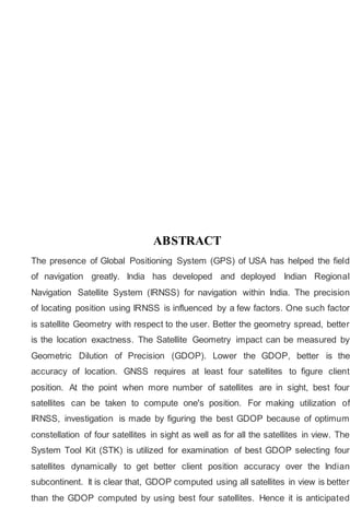
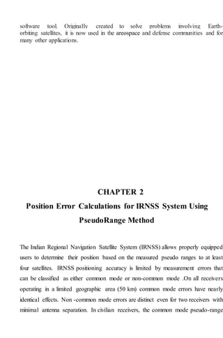
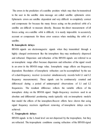
![d. Time Dilution of Precision (TDOP): It is a measure of uncertainty in receiver
clock GPS position accuracy is the combined effect of the measurement errors and
satellite geometry. Measurement errors and biases can be represented by User
Equivalent Range Error (UERE).UERE is defined as the root sum square of the
various errors and biases. Multiplying UERE with GDOP gives expected accuracy
of the GPS positioning at one-sigma (1-σ) level and is given in Eq.6.
GPS Position accuracy = UERE ×GDOP (6)
DOP Ratings are listed in the Table
Table 1 DOP Ratings [LANGLEY, R.B., 1999]
DOP VALUE Ratings
1 ideal
2-4 Execllent
4-6 Good
6-8 Moderate
8-20 Fair
20-25 Poor
V.Systems ToolKit
Satellite Tool Kit, often referred to by its initials STK, is a physics-based software
package from Analytical Graphics, Inc. that allows engineers and scientists to
perform complex analyses of ground, sea, air, and space platforms, and share results
in one integrated environment. At the core of STK is a geometry engine for
determining the time-dynamic position and attitude of objects ("assets"), and the
spatial relationships among the objects under consideration including their
relationships or accesses given a number of complex, simultaneous constraining
conditions. STK has been developed since 1989 as a commercial off the shelf](https://image.slidesharecdn.com/projecteceb-200531171836/85/Projecteceb-14-320.jpg)
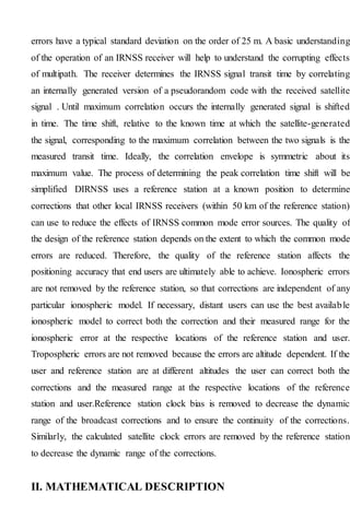
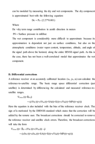

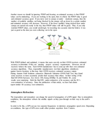
![2. Restricted/Authorized Service (RS)
The SPS and RS services are provided by using two IRNSS
signals: L5 (1176.45 MHz) and S (2492.08 MHz). SPS service utilizes
binary phase shift keying (BPSK) whereas a binary offset carrier [BOC
(5,2)] modulation .
In order to improve the accuracy of positioning solution, the IRNSS
system can be combined with GNSSconstellation .IRNSSservices can be
used in wide range of civilian applications as it is an alternative for GPS
in providing positioning services with better accuracy . The error budget
of the proposed IRNSS is given below in Table.
3 Geometric Dilution of Precision
In any navigation system, accuracy of position estimation is the
measure of the system’s positioning performance. The accuracy of
positioning solution is affected by several fac- tors such as refraction
of the signal in atmosphere during its propagation form satellite to
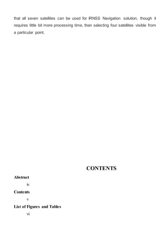
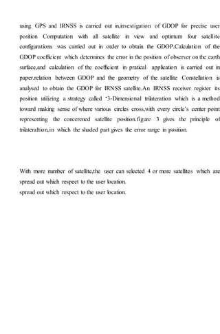
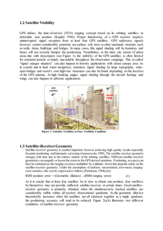
Table 1 Co-ordinates of IRNSS satellites launched till date
the receiver, multipath, satellite clock error and the geometry of the
satellites as seen by the receiver [14].
Satellite Orbit Latitude (°) Longitude (°) Height
(km)
IRNSS-1A Geo Synchronous 29 North 55 East 35,786
IRNSS-1B Geo Synchronous 29 North 55 East 35,786
IRNSS-1C Geo Stationary 0 83 East 35,786
IRNSS-1D Geo Synchronous 30.5 North 111.75 East 35,786
GEOS2a Geo Stationary 0 34 East 35,786
GEOS3a Geo Stationary 0 131.5 East 35,786
GSOS4a Geo Synchronous 30.5 North 111.75 East 35,786](https://image.slidesharecdn.com/projecteceb-200531171836/85/Projecteceb-23-320.jpg)
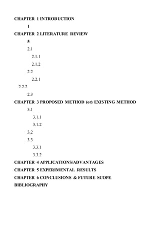
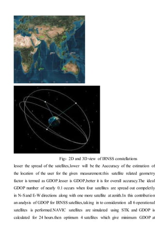
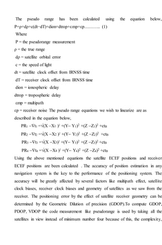
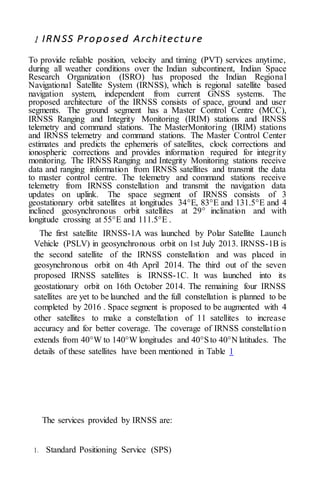
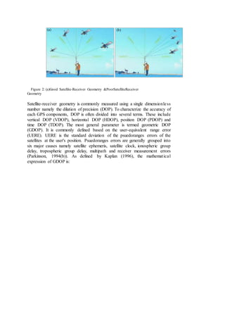
![IMPACT OF DOP FOR
POSITION COMPUTATION IN
IRNSS
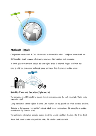
Newly IRNSS system from Indian Space Research Orga- nization (ISRO)
will provide two types of services one is Special Positioning Service (SPS)
and another is Precision Service (PS) [5]. The expected position accuracy
of both the services is approximately 20m for the 1500km region around
the India and less than 10m of accuracy within the region of India [6].
The received signal from satellites is always affected by unintentional
sources of error like, propagation error, multipath error, receiver clock
error, satellite orbit error, satellite position, geometry, random
measurement noise error and satellite clock offset [7–9].
Dilution Of Precision (DOP) is widely used to measure ac- curacy of
navigation and tracking systems [10]. High accuracy requires accurate
measurement of the range and it depends on good geometric relationship
between the satellite and the measuring device [9–11]. Here, the different
DOP parameter like, Geometric Dilution Precision (GDOP), Position
Dilution Precision (PDOP), Horizontal Dilution Precision (HDOP),
Vertical Dilution Precision (VDOP) and Time Dilution Pre- cision (TDOP)
are encapsulated with detailed mathematical outcomes.
In this paper, different DOP parameters are analyzed with respect to
Elevation and Azimuth angle of satellites for differ- ent system
combination like, IRNSS, GPS and an augmented GPS+IRNSS. It has
been observed that if more number of satellites are visible than
performance of IRNSS system is better and measured DOP value is
optimum. Here simulation is performed in MATLAB on the data of
different months col- lected by the ACCORD IRNSS receiver at Advance
Research Lab, Electronics Engineering Department SVNIT, Surat, India.
Section II gives a description of the newly IRNSS system. Section III
covered brief derivation of all DOP parameters. DOP parameter results
have been compared in section IV. Conclusions has been encapsulate.
IRNSS SYSTEM DESCRIPTION](https://image.slidesharecdn.com/projecteceb-200531171836/85/Projecteceb-26-320.jpg)
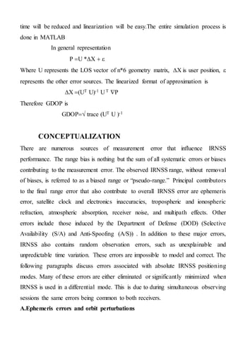
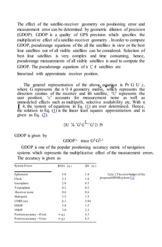
![IRNSS is a self reliant, aboriginal developed satellite based navigation
system, which is evolved and restrained by the ISRO [1]. IRNSS has been
developed to provide services to the military as well as civilian users in
any hostile situations towards the Indian region and region extended up to
1500km [2] [3].
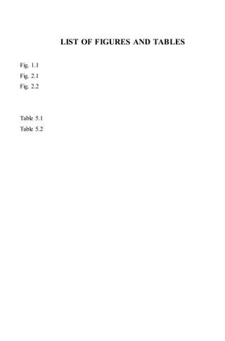
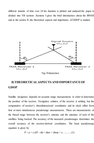
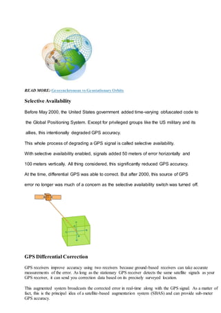
The architecture of IRNSS is shown in Fig.1. IRNSS con- sists of three
segments, Space Segment (SS), Ground Segment (GS) and User Segment
(US). The SS has a constellation of seven satellites, the six satellites are
already placed in the orbit and last satellite is expected to launch in June
2016 [2].
The US provides two types of services (SPS and PS) with two different
signals [3], one with a carrier frequency of
Fig. 1. IRNSS System Architecture](https://image.slidesharecdn.com/projecteceb-200531171836/85/Projecteceb-27-320.jpg)
![Fig. 2. Position
Determination [7]
1176.45 MHz in L5 band (1164.45 to 1188.45 MHz) and another with 2492.08 MHz in S band (2483.5 to
2500 MHz) [5]. PS is also called Restricted Service (RS) as it will be used in defense application, so it is
encoded and modulated by Binary Offset Carrier (BOC)(5,2) [6]. Where, the SPS is modulated by Binary
Phase Shift Keying (BPSK) modulation and it will provide services to all civilian users [7].
The GS is amenable for the up keeping and operation of the IRNSS constellation [12]. It contains different
service and control station like ISRO Navigation Centre (INC), IRNSS Spacecraft Control Facility (ISCF),
IRNSS Range and In- tegrity Monitoring Stations (IRIMC), IRNSS Network Tim- ing Centre (INTC), IRNSS
CDMA Ranging Station (ICRS), Laser Ranging Stations (LRS), Data Communication Network (DCN) [1]
[13].
The IRNSS-1A, 1B, 1C, 1D, 1E and 1F were successfully launched by Polar Satellite Launch Vehicle PSLV-
C22, PSLV- C24, PSLV-C26, PSLV-C27, PSLV-C31 and PSLV-C32 in July
2013, April 2014, October 2014, March 2015, January 2016 and March 2016 respectively. The last satellite
IRNSS-1G will be launched in April 2016 and the complete constellation of IRNSS will be done .
III. POSITION DETERMINATION
The determination of a point position using a satellite system on the earth, uses a method for sublunary
surveying called trilateration (distance measured by electronic equipment) [8][12]. The user of IRNSS receiver
solely measures the ranges between the earth and satellites. The user’s 3D (Latitude, Longitude and Altitude)
position is determined by finding the intersection point of the observed ranges from at least 3 satellites [9][14].
But to make a more accurate position measurement, one more satellite range observation is required to resolve
timing offset problem as shown in Fig.2 [7]. As described above, the calculated delay true but it is Psuedorange
and represented as a P and given by [9] suffers from various error sources, the range measured by different
satellites is notRt
P = c[(Tu + tu)−(Ts −δt)] + d + mpp + np
= c(Tu −Ts)+c(tu −δt)] + d + mpp + np Pi………..1
= Rt i + c(Δt)+di + mpp + np
Where, Tu and Ts are the time instants when signal left from the satellites and signal reached at the satellites,
respectively. Rt i is a true distance between the satellite and user [10]. It can be calculated using,
Rt i =(xis −xu)2 +(yis −yu)2 +(zis −zu)2](https://image.slidesharecdn.com/projecteceb-200531171836/85/Projecteceb-28-320.jpg)
![When four pseudoranges are observed, then i ranges from 1 to 4. (Xs, Y s, Zs) denotes 3D known geocentric
coordinates of satellites and (Xu, Y u, Zu) are unknown geocentric coordinates of the user which are to be
computed [11]. c is the velocity of propagation. Δt is the total time offset between satellites and receiver.
Where, tu and δt are the clock offset from system time for receiver and satellite respectively [12]. d is the
total atmospheric delay So,
d = Ipr + Tr
Where, Ipr code delay due to Ionosphere, which will be always positive in magnitude and Tr is the code delay
because of troposphere which is independent of frequency [13]. mpp and np shows the effect due to
psuedorange multipath delay and other pseudorange measurement noise [8][14]. The pseudorange
measurement equation (1) can be rewritten by considering only four unknown parameters
Pt i =(xis −xu)2 +(yis −yu)2 +(zis −zu)2 + ctu
= f(xu,yu,zu,tu) (2)
Equation (2) is a function of four unknown parameter, xu,yu,zu and tu and suppose its approximate values are
ˆ xu, ˆy u, ˆ zu and ˆ tu then
ˆ Pt i = (xis − ˆ xu)2 +(yis − ˆ yu)2 +(zis − ˆ yu)2 + ctu
= f( ˆ xu, ˆ yu, ˆ zu, ˆ tu)
So, the equation (3) is modified as
f(xu,yu,zu,tu)=f( ˆ xu+Δxu, ˆ yu+Δyu, ˆ zu+Δzu, ˆ tu+Δtu) (4)
By applying Taylor series expansion [12],
f( ˆ xu+Δxu, ˆ yu+Δyu, ˆ zu+Δzu, ˆ tu+Δtu)=f( ˆ xu, ˆ yu, ˆ zu, ˆ tu)
+df( ˆ xu, ˆ yu, ˆ zu, ˆ tu) d ˆ xu/Δxu + df( ˆ xu, ˆ yu, ˆ zu, ˆ tu) d ˆ yu/Δyu
+df( ˆ xu, ˆ yu, ˆ zu, ˆ tu) d ˆ zu/Δzu + df( ˆ xu, ˆ yu, ˆ zu, ˆ tu) dtu/Δtu + ..... (5)
Where, dxj, dyj and dzj are the cosine unit pointing vector between users and ith satellites position [14]. By
putting the solution represented in equation (6) into equation (5)
f( ˆ xu+Δxu, ˆ yu+Δyu, ˆ zu+Δzu, ˆ tu+Δtu)−f( ˆ xu, ˆ yu, ˆ zu, ˆ tu)
ΔPti = dxiΔxu + dyiΔyu + dziΔzu −cΔtu (7)
In matrix form [7]
finally,
ΔPt = A∗ΔU (9)
The solution to the nonlinear IRNSS measurement is [3]
δU =(A)−1δPt (10)](https://image.slidesharecdn.com/projecteceb-200531171836/85/Projecteceb-29-320.jpg)
![Where,matrix“A”isthereceivertosatellitesinthespaceLOS vectors , δPt is the matrix of the psuedorange
measurement and Navigation Error State Vector (NESV) is represented by
δU [10].
Suppose more than 4 satellites are in view , then
δU =(ATA)−1ATδpt (11)
If δU is Zero Mean Vector (ZMV) of user estimated error, then the statistics of δU is providing information
of the expected position errors. Using the law of inverse of A(A−1), the covariance of δU can be found as
[12]
cov(δU)=E[δUδUT]
= E[(ATA)−1)ATδPδP TA(ATA)−T]
=(ATA)−1ATE[δPtδPtT]A(ATA)−T
=(ATA)−1ATcov(δPt)A(ATA)−T
The pseudorange errors are nothing but it is represented by cov(δPt)[9]. These errors have a Gaussian random
variable and it is assumed that they are uncorrelated and statistically independent, So as a results diagonal
covariance matrix. Further, it is assumed that all satellites have a same range measurement error, which is
denoted by (σn). Hence, cov(δPt) can be represented as
cov(δPt)=σn2I (13)
Now substituting equation (13) in equation (12), covariance of δU can be written as [12]
E[δUδUT]=σn2(ATA)−1ATA(ATA)−T = σn2(ATA)−T (14)
As (ATA) is symmetric, transpose is not required. Therefore,
cov(δU)=σn2(ATA)−1 (15)
The elements of G provides a information of geometry of the satellite-receiver i.e. DOP and various DOPs
values which can be evaluated from the diagonal elements of G[10]
σx2 + σy2 + σz2 + σb2 =(Gxx + Gyy + Gzz + Gbb)σn2
σx2 + σy2 + σz2 + σb2 = σn ∗GDOP
Therefor [8]
GDOP = σx2 + σy2 + σz2 + σb2/ σn
= (Gxx + Gyy + Gzz + Gbb) (18)
PDOP = σx2 + σy2 + σz2/ σn
= (Gxx + Gyy + Gzz) (19)
HDOP = σx2 + σy2 /σn
= (Gxx + Gyy) (20)
VDOP=σZ/ σn
=(Gzz) (21)
TDOP =σb/ σn
=(Gbb) (22)](https://image.slidesharecdn.com/projecteceb-200531171836/85/Projecteceb-30-320.jpg)
![These DOP terms can be related as [7] [9]
PDOP2 = HDOP2 + VDOP2 (23)
GDOP2 = PDOP2 + TDOP2 (24)
Finally, 3D RMS, position and clock bias estimation error are given by σn.GDOP [12]. This relation show
that the position estimation depends upon two term (i) variance of the range error σn, and (ii) a term which
depends entirely on the usersatellite geometr
POSITIONING DILUTION OF PRECISION
DOP stands for Dilution of Precision. Dilution of Precision is a term used to describe the strength
of the current satellite configuration, or geometry, on the accuracy of the data collected by a GPS
or GNSS receiver at the time of use. Thus, PDOP is Position of DOP and can be thought of as 3D
positioning or the mean of DOP, and most often referred to in GPS; HDOP is Horizontal of DOP;
VDOP is Vertical of DOP. GPS and GNSS receivers communicate with the satellites above
to triangulate our position. Satellites are very good at triangulating our horizontal position, and
less accurate at vertical positions. This can be thought of in the similar way our phone communicates
with cell towers to roughly triangulate our position. With GPS receivers, when satellites are grouped
together in the same general area of the sky, the satellite geometry is considered to be weak (higher DOP
value). When satellites are evenly spread throughout the sky, their geometry is considered strong (lower
DOP value). Thus, the more satellites available spread evenly throughout the sky, the better our positional
accuracy will be (and the lower the PDOP value).
Older GPS receivers were not equipped with accuracy algorithms to estimate the horizontal and
vertical accuracy of the data being collected. Because of this, we were trained to watch our PDOP
values with the rough idea that values below 6 were good enough and values below 4 were great.
Values at 9 or higher meant that the user shouldn’t rely on the accuracy of that data and should
wait until a better PDOP value could be attained by the satellites moving into preferable positioning
in the sky (or spreading out). Personally, I remember using Trimble Geo handhelds in the mid-00’s
where for a whole summer the PDOP value floated around the 9 range from about 11:30 am to 1 pm
every day, with better values in the morning and late afternoon. Luckily, those days of poor PDOP
values are long gone with the advent of GNSS receivers that are capable of tracking GPS and Glonass
satellites and the addition of more satellites. The better GNSS receivers today can track more than
2 satellite constellations, giving them access to many more satellites simultaneously. Because of
3 this, in practice, we rarely see PDOP values greater than 4 for work in the continental U.S.](https://image.slidesharecdn.com/projecteceb-200531171836/85/Projecteceb-31-320.jpg)


![BIBLIOGRAPHY (font size 16)
All references should be in the following model
[1] N.Mitianoudis and T.Stathaki, “Pixel-based and region-based image fusion schemes using
ICA bases,” Information fusion, vol. 8, no. 2, pp. 131-142, 2007.
[2] P.J.Burt and R.J.Kolczynski, “Enhanced image capture through fusion,” IEEE International
Conference on Computer Vision, pp. 173-182, 1993.
[3] P.J.Burt and E.H.Adelson, “The laplacian pyramid as a compact image code,” IEEE
Transactions on Communications, vol. 31, no. 4, pp. 532-540, 1983.
[4] A.Toet, J.J.Van Ruyven, and J.M.Valeton, “Merging thermal and visual images by a
contrast pyramid,” Optical Engineering, vol. 28, no. 7, pp. 789-792, 1989.
[5] www.wikipedia.org
[6] www.imagefusion.org](https://image.slidesharecdn.com/projecteceb-200531171836/85/Projecteceb-40-320.jpg)


![GPS [ Global Positioning System ]](https://cdn.slidesharecdn.com/ss_thumbnails/finalgps-termpaper-141116110156-conversion-gate02-thumbnail.jpg?width=640&height=640&fit=bounds)


