Download to read offline
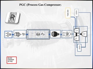


The document outlines Ashwin Anil's winter internship at J.P.C Enterprises focusing on the overhauling process of a power turbine (PT) and a process gas compressor (PGC). It details the step-by-step procedures followed during the overhauling, challenges faced, and methods used, as well as the instruments and tools utilized throughout the process. The internship provided practical insights into machinery operations, reinforcing the theoretical knowledge gained in mechanical engineering studies.


