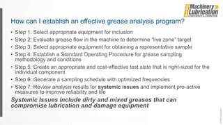
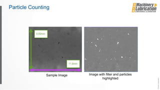
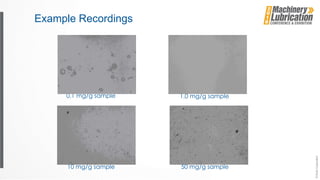
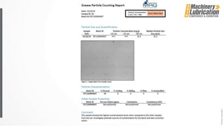
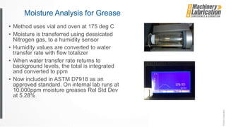
A Proactive Grease Analysis Strategy for
Critical Equipment
Ensuring a clean and dry grease supply through inspection,
testing and corrective actions
Why Grease Analysis?
• Some critical machines are grease
lubricated, and they can fail
• Prior to failure, information in present in the
grease that can lead to early detection
• Root-cause determination is possible in
analyzing for contaminants, the wrong or
mixed greases, or wear modes such as
fretting, fatigue, abrasive and adhesive wear
• Not all new greases are clean: you can’t
filter a grease so initial cleanliness from the
grease gun or auto-luber is paramount to
long machine life
Grease Sampling
• Difficult challenges in gathering representative grease
samples
• Sampling from robots
• Wind turbine samples (main, blade, generator, etc.)
• Electric motors
• Pillow block bearings
• Motor Operated Valves (MOVs and valve stems)
• Slewing bearings and other mining applications
• Monitoring new grease supplies
Paths of grease entering a bearing
How can I establish an effective grease analysis program?
• Step 1: Select appropriate equipment for inclusion
• Step 2: Evaluate grease flow in the machine to determine “live zone” target
• Step 3: Select appropriate equipment for obtaining a representative sample
• Step 4: Establish a Standard Operating Procedure for grease sampling
methodology and conditions
• Step 5: Create an appropriate and cost-effective test slate that is right-sized for the
individual component
• Step 6: Generate a sampling schedule with optimized frequencies
• Step 7: Review analysis results for systemic issues and implement pro-active
measures to improve reliability and life
Systemic Issues include dirty and mixed greases that can
compromise lubrication and damage equipment
Grease Thief Samplers
• Obtain 1 gram grease sample
• Multiple locations from the same container
• Use of “Handle” tools to set depth
• Sampler designed to optimize the analysis process
Pillow Block Electric Motor Grease Thief SlimTM
MOV Gearbox Robot Kit Wind Turbine
Analysis Techniques: ASTM D7918
• ASTM D7918
approved and
published in 2015.
• Particle counting
and moisture ppm
capabilities added
recently
• 6 tests with 1-gram
of grease
Ferrous
debris
Die
Extrusion
Colorimetry Linear Sweep
Voltammetry
Elemental
Spectroscopy
FTIR
Water in
ppm
Protecting New Grease Supplies
• Key parameters to spot check and periodically evaluate:
• Cleanliness
• Particulate
• Moisture
• Mixing
• Color
• Batch variation
• Color
• Mis-labeling
• Color
• Color – Particulate – Moisture
New Method: Particle Counting in Integrated
Tester D7918-17
• New method uses ASTM D7718 sampling standard capture device for
presentation of 1 gram representative sample
• Samples can be obtained from:
• new grease in manufacturing process
• packaged new greases upon opening
• stored greases in opened packages
• grease guns and auto-lubers
• inservice samples in the machine
• Method sizes and counts particles reliably down to 10 micron in major axis,
and provides aspect ratio and other characterization information
Camera Set-up
• Thin Film extrusion sample
preparation
• Lens magnification to achieve 10
micron particle resolution
• Backlit with LED lighting
Particle Counting Example
Particle Counting
Sample Image Image with filter and particles
highlighted
Example Recordings
50 mg/g sample10 mg/g sample
1.0 mg/g sample0.1 mg/g sample
Moisture Analysis for Grease
• Method uses vial and oven at 175 deg C
• Moisture is transferred using dessicated
Nitrogen gas, to a humidity sensor
• Humidity values are converted to water
transfer rate with flow totalizer
• When water transfer rate returns to
background levels, the total is integrated
and converted to ppm
• Now included in ASTM D7918 as an
approved standard. On internal lab runs at
10,000ppm moisture greases Rel Std Dev
at 5.28%
Measuring Grease Color
• The appearance of grease is variable based on ambient conditions
• When ambient conditions are controlled, changes in grease color
can indicate differences of varying significance
• Mixing of greases with different color greases
• Accumulation of debris (wear, contaminants) in grease
• Oxidation or aging of grease
• Color change itself does not dictate an unacceptable change in
performance, but may be a warning parameter for further
investigation
• Comparision to new grease can help determine need for further
testing in service
• Checking new grease batches to confirm consistent product
18
L*
40
50
60
70
80
90
a*
40
50
60
70
80
90
b*
40
50
60
70
80
90
CIE color space chromaticity diagram
ASTM E308 Defines CIE Color
a* is the change in color in the red spectrum.
a* is positive in the red direction and negative in the
green direction.
b* is the change in color of the yellow spectrum.
b* is positive in the yellow direction and negative in the
blue direction.
L* is the change in shade from white to black.
Grease Color Examples
• Three different
greases
• Follows the patterns
identified by the
chromaticity diagram
Colors Sample 1 2 3
Light…dark
L* 48.6 63.5 61.3
Red…green
a* 42.5 13.6 25.8
Yellow…Blue
b* -14.0 -52.1 3.8
Grease Thief Colorimeter
• Controls optical pathlength to
0.035, 0.010, and 0.005”
• D50 and D65 light sources
• RGB, CIE and other color
measurements
Grease under varying conditions
New grease (Vigo)
Significantly dark (3418)
Moderately dark (384)
Slightly dark (389)
Significantly dark (391)
#3481: 0.035” path, 0.010” path, & 0.005” path
#391: 0.035” path, 0.010” path, & 0.005” path
#389: 0.035” path, 0.010” path, & 0.005” path
#384: 0.035” path & 0.010” path
Some Grease Thief Users
Thank you.

Proactive Grease Analysis - 2018 Machinery Lubrication Conference

  • 1.
    A Proactive GreaseAnalysis Strategy for Critical Equipment Ensuring a clean and dry grease supply through inspection, testing and corrective actions
  • 2.
    Why Grease Analysis? •Some critical machines are grease lubricated, and they can fail • Prior to failure, information in present in the grease that can lead to early detection • Root-cause determination is possible in analyzing for contaminants, the wrong or mixed greases, or wear modes such as fretting, fatigue, abrasive and adhesive wear • Not all new greases are clean: you can’t filter a grease so initial cleanliness from the grease gun or auto-luber is paramount to long machine life
  • 3.
    Grease Sampling • Difficultchallenges in gathering representative grease samples • Sampling from robots • Wind turbine samples (main, blade, generator, etc.) • Electric motors • Pillow block bearings • Motor Operated Valves (MOVs and valve stems) • Slewing bearings and other mining applications • Monitoring new grease supplies
  • 4.
    Paths of greaseentering a bearing
  • 5.
    How can Iestablish an effective grease analysis program? • Step 1: Select appropriate equipment for inclusion • Step 2: Evaluate grease flow in the machine to determine “live zone” target • Step 3: Select appropriate equipment for obtaining a representative sample • Step 4: Establish a Standard Operating Procedure for grease sampling methodology and conditions • Step 5: Create an appropriate and cost-effective test slate that is right-sized for the individual component • Step 6: Generate a sampling schedule with optimized frequencies • Step 7: Review analysis results for systemic issues and implement pro-active measures to improve reliability and life Systemic Issues include dirty and mixed greases that can compromise lubrication and damage equipment
  • 6.
    Grease Thief Samplers •Obtain 1 gram grease sample • Multiple locations from the same container • Use of “Handle” tools to set depth • Sampler designed to optimize the analysis process
  • 7.
    Pillow Block ElectricMotor Grease Thief SlimTM MOV Gearbox Robot Kit Wind Turbine
  • 8.
    Analysis Techniques: ASTMD7918 • ASTM D7918 approved and published in 2015. • Particle counting and moisture ppm capabilities added recently • 6 tests with 1-gram of grease Ferrous debris Die Extrusion Colorimetry Linear Sweep Voltammetry Elemental Spectroscopy FTIR Water in ppm
  • 9.
    Protecting New GreaseSupplies • Key parameters to spot check and periodically evaluate: • Cleanliness • Particulate • Moisture • Mixing • Color • Batch variation • Color • Mis-labeling • Color • Color – Particulate – Moisture
  • 10.
    New Method: ParticleCounting in Integrated Tester D7918-17 • New method uses ASTM D7718 sampling standard capture device for presentation of 1 gram representative sample • Samples can be obtained from: • new grease in manufacturing process • packaged new greases upon opening • stored greases in opened packages • grease guns and auto-lubers • inservice samples in the machine • Method sizes and counts particles reliably down to 10 micron in major axis, and provides aspect ratio and other characterization information
  • 11.
    Camera Set-up • ThinFilm extrusion sample preparation • Lens magnification to achieve 10 micron particle resolution • Backlit with LED lighting
  • 12.
  • 13.
    Particle Counting Sample ImageImage with filter and particles highlighted
  • 14.
    Example Recordings 50 mg/gsample10 mg/g sample 1.0 mg/g sample0.1 mg/g sample
  • 16.
    Moisture Analysis forGrease • Method uses vial and oven at 175 deg C • Moisture is transferred using dessicated Nitrogen gas, to a humidity sensor • Humidity values are converted to water transfer rate with flow totalizer • When water transfer rate returns to background levels, the total is integrated and converted to ppm • Now included in ASTM D7918 as an approved standard. On internal lab runs at 10,000ppm moisture greases Rel Std Dev at 5.28%
  • 17.
    Measuring Grease Color •The appearance of grease is variable based on ambient conditions • When ambient conditions are controlled, changes in grease color can indicate differences of varying significance • Mixing of greases with different color greases • Accumulation of debris (wear, contaminants) in grease • Oxidation or aging of grease • Color change itself does not dictate an unacceptable change in performance, but may be a warning parameter for further investigation • Comparision to new grease can help determine need for further testing in service • Checking new grease batches to confirm consistent product
  • 18.
    18 L* 40 50 60 70 80 90 a* 40 50 60 70 80 90 b* 40 50 60 70 80 90 CIE color spacechromaticity diagram ASTM E308 Defines CIE Color a* is the change in color in the red spectrum. a* is positive in the red direction and negative in the green direction. b* is the change in color of the yellow spectrum. b* is positive in the yellow direction and negative in the blue direction. L* is the change in shade from white to black.
  • 19.
    Grease Color Examples •Three different greases • Follows the patterns identified by the chromaticity diagram Colors Sample 1 2 3 Light…dark L* 48.6 63.5 61.3 Red…green a* 42.5 13.6 25.8 Yellow…Blue b* -14.0 -52.1 3.8
  • 20.
    Grease Thief Colorimeter •Controls optical pathlength to 0.035, 0.010, and 0.005” • D50 and D65 light sources • RGB, CIE and other color measurements
  • 21.
    Grease under varyingconditions New grease (Vigo) Significantly dark (3418) Moderately dark (384) Slightly dark (389) Significantly dark (391)
  • 22.
    #3481: 0.035” path,0.010” path, & 0.005” path
  • 23.
    #391: 0.035” path,0.010” path, & 0.005” path
  • 24.
    #389: 0.035” path,0.010” path, & 0.005” path
  • 25.
    #384: 0.035” path& 0.010” path
  • 26.
  • 27.