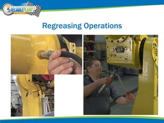
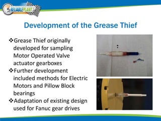
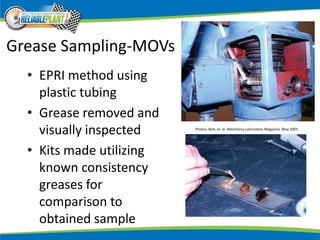
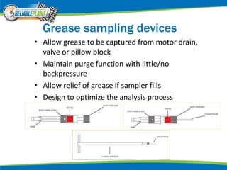
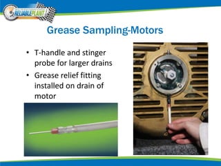
Grease Sampling and Analysis for
Robotic Gear Drives
Rich Wurzbach, CLS, LLA, ASNT PdM Level III
MRG Labs
York, PA, USA
Robotic Gear Drives
Robot systems expanding use in
manufacturing
Auto manufacturing a leading use of robots
Fanuc is leader in market; 240,000 robots
deployed worldwide, 100,000 in N. America
Fanuc robots are six-axis, include a grease
lubricated gear drive in each joint/axis
Robot Drive Maintenance
Grease in gear drive requires periodic
replacement
Life of grease is dependent on cycle times,
degree of movement, load, temperature and
thermal cycling, and contaminants
Manufacturer recommendations are uniform and
time-based only
High cost of grease and downtime make good
candidate for condition-based relubrication
Fanuc Robot Styles
Regreasing Operations
Gear Drive Access Points
 An entry and exit point for
each gearbox enclosure
 Entry is a Zerk fitting, with a
small threaded opening (M6)
 Exit is M12 threaded plug for
900 series and larger on most
robots, some are smaller M6
 Drain is removed with allen
wrench
 Grease gun is used at Zerk
fitting to add new grease and
to purge out old grease
Goal: Develop routine sampling method
Method should be minimally invasive
Samples should be available without
disassembling robot
Ideally performed between regularly
scheduled purge grease changeouts
Method should leave robot in a ready-to-run
state (purged of excess grease)
Development of the Grease Thief
Grease Thief originally
developed for sampling
Motor Operated Valve
actuator gearboxes
Further development
included methods for Electric
Motors and Pillow Block
bearings
Adaptation of existing design
used for Fanuc gear drives
Grease Sampling-MOVs
• EPRI method using
plastic tubing
• Grease removed and
visually inspected
• Kits made utilizing
known consistency
greases for
comparison to
obtained sample
Photos: Bolt, et. al. Machinery Lubrication Magazine. May 2003
Grease sampling devices
• Allow grease to be captured from motor drain,
valve or pillow block
• Maintain purge function with little/no
backpressure
• Allow relief of grease if sampler fills
• Design to optimize the analysis process
Grease Sampling-Motors
• T-handle and stinger
probe for larger drains
• Grease relief fitting
installed on drain of
motor
Kit for Robot Drive Sampling
First version – Grease purge and capture
Gearbox must be filled in order to force
purge
Pressure from exiting grease fills Grease
Thief
Excess grease must be purged following
sampling, prior to return to service
Adapter for larger drains
 Works for larger drains (M12)
 When used as an expander for smaller drains, determined to
be inadequate—creation of excessive backpressure and
possible compromise of seals--REJECTED
Problems with original method
• Use of reducers in some cases can constrict
flow in drain
• Getting a sample requires filling the gearbox
completely with grease, then obtaining the
sample, then purging back to appropriate
volume
• Can consume large amount of grease in the
sampling process
• May still be required for degraded greases
that have hardened in service
New Kit for Robot Sampling
Low consistency of grease allows for suction to be used
in most cases
A sealing syringe, with the gearbox in the right position,
allows supply-side sampling in some but not all cases
Grease Thief is threaded into purge drain and sample is
drawn in some smaller gears (J4-J6)
Sampling method for Fanuc Gear Drives meets ASTM
D7718 – 11: Standard Practice for Obtaining In-Service
Samples of Lubricating Grease
Syringe suction method
 Syringe with tapered tip is threaded
into Zerk fitting thread, cutting into
plastic
 Seal is made with reservoir, allowing
suction of very fluid greases only
 Orientation of joint is important in
ensuring grease is close to zerk hole
 Syringe is filled with about 10ml
grease, so that the first 1-2ml
dispensed into Grease Thief is after
the purge volume
 If grease has degraded or hardened,
suction method may not work;
purge method may be required
New Kit for Robot Sampling-Direct
suction from Grease Thief on J4-J6
Samples submitted for Analysis
• Samples are
gathered in or
transferred to
Grease Thief for
uniform geometry
• Samples are
protected in tube
• Labeling can include
barcodes for
definitive
equipment ID
Additional Use – Tidy grease purge
Grease purge required with any
relubrication task
Operating robot through degrees of
movement with drain open
To avoid mess, plastic bags taped to drain,
or channel constructed with tape to lead
grease to floor
Additional Use – Tidy grease purge
Use of Grease Thief body
Thread size matches drain
thread for secure installation
With internals removed, bag is
tie-wrapped onto open end to
capture all grease
All joints can be fitted for
capture, and a single, multi-axis
purge can be performed, saving
time
Multi-point Purge
Empty Grease Thief
bodies are threaded to
the purge holes
Capture bag is tie-
wrapped to the body
Robot is programmed
for a multi-axis
movement that
optimizes purge of
excess grease
Grease can be disposed
prior to the installation
of the drain plug
Analysis of Grease from Robots
• Tests to be performed include Wear,
Consistency, Contamination, and Oxidation
• Oxidation used to evaluate relative stresses on
the grease in each robot joint, and across
robots in the facility
• Higher ambient temperatures, higher loads,
and more rapid movements potentially age
grease more rapidly
Analysis Techniques
Sample received fdM+ is run Grease Thief Analyzer is performed and
substrate is made
Two strips are used to make
a dilution to run RDE.
One Strip is used
for FT-IR.
One Strip is Dissolved in
RULER solution to run RULER.
Wear levels in Robot fleet-comparison
Die Extrusion Test
•Samplers loaded into fixture with load cell at pusher end
•Grease extruded through die to create ribbon on substrate
•Load profile at varying speeds developed for consistency evaluation
•Sample prepared for subsequent analyses
Consistency Monitoring
The graph shows the results from the Grease Thief Die Extrusion Test. The
consistency has greatly dropped as compared to the grade 2 grease.
Anti-Oxidant Monitoring
•Samples from similar gearboxes,
same time in service
•Both have an adequate remaining
anti-oxidant level to protect grease
from oxidation
•Lower sample shows more rapid
degradation of anti-oxidants, due
to higher temperatures,
contaminants, or other oxidation
stressors.
•Differences in time of service or
relubrication quantities or
effectiveness could also affect anti-
oxidant amount
Methods to identify grease mixing
• Grease Colorimetry spectrum identifies visible changes in the
grease (400 – 700 nm)
• FT-IR looks at chemical bonds and can identify different thickener
types and signs of oxidation.
• Molywhite and Vigogrease have very different signatures, and can
be differentiated, or mixtures identified
Summary
• Grease samples can be used to evaluate wear
condition and predict component failures
• Changeouts can be condition-based,
compensating for non-uniform conditions of
load, environment and service
• Mixing and improper grease use can be
identified and corrected before damage
occurs

Rp2012 wurzbach robot-greaseanalysis_2012

  • 1.
    Grease Sampling andAnalysis for Robotic Gear Drives Rich Wurzbach, CLS, LLA, ASNT PdM Level III MRG Labs York, PA, USA
  • 2.
    Robotic Gear Drives Robotsystems expanding use in manufacturing Auto manufacturing a leading use of robots Fanuc is leader in market; 240,000 robots deployed worldwide, 100,000 in N. America Fanuc robots are six-axis, include a grease lubricated gear drive in each joint/axis
  • 3.
    Robot Drive Maintenance Greasein gear drive requires periodic replacement Life of grease is dependent on cycle times, degree of movement, load, temperature and thermal cycling, and contaminants Manufacturer recommendations are uniform and time-based only High cost of grease and downtime make good candidate for condition-based relubrication
  • 4.
  • 5.
  • 6.
    Gear Drive AccessPoints  An entry and exit point for each gearbox enclosure  Entry is a Zerk fitting, with a small threaded opening (M6)  Exit is M12 threaded plug for 900 series and larger on most robots, some are smaller M6  Drain is removed with allen wrench  Grease gun is used at Zerk fitting to add new grease and to purge out old grease
  • 7.
    Goal: Develop routinesampling method Method should be minimally invasive Samples should be available without disassembling robot Ideally performed between regularly scheduled purge grease changeouts Method should leave robot in a ready-to-run state (purged of excess grease)
  • 8.
    Development of theGrease Thief Grease Thief originally developed for sampling Motor Operated Valve actuator gearboxes Further development included methods for Electric Motors and Pillow Block bearings Adaptation of existing design used for Fanuc gear drives
  • 9.
    Grease Sampling-MOVs • EPRImethod using plastic tubing • Grease removed and visually inspected • Kits made utilizing known consistency greases for comparison to obtained sample Photos: Bolt, et. al. Machinery Lubrication Magazine. May 2003
  • 10.
    Grease sampling devices •Allow grease to be captured from motor drain, valve or pillow block • Maintain purge function with little/no backpressure • Allow relief of grease if sampler fills • Design to optimize the analysis process
  • 11.
    Grease Sampling-Motors • T-handleand stinger probe for larger drains • Grease relief fitting installed on drain of motor
  • 12.
    Kit for RobotDrive Sampling First version – Grease purge and capture Gearbox must be filled in order to force purge Pressure from exiting grease fills Grease Thief Excess grease must be purged following sampling, prior to return to service
  • 13.
    Adapter for largerdrains  Works for larger drains (M12)  When used as an expander for smaller drains, determined to be inadequate—creation of excessive backpressure and possible compromise of seals--REJECTED
  • 14.
    Problems with originalmethod • Use of reducers in some cases can constrict flow in drain • Getting a sample requires filling the gearbox completely with grease, then obtaining the sample, then purging back to appropriate volume • Can consume large amount of grease in the sampling process • May still be required for degraded greases that have hardened in service
  • 15.
    New Kit forRobot Sampling Low consistency of grease allows for suction to be used in most cases A sealing syringe, with the gearbox in the right position, allows supply-side sampling in some but not all cases Grease Thief is threaded into purge drain and sample is drawn in some smaller gears (J4-J6) Sampling method for Fanuc Gear Drives meets ASTM D7718 – 11: Standard Practice for Obtaining In-Service Samples of Lubricating Grease
  • 16.
    Syringe suction method Syringe with tapered tip is threaded into Zerk fitting thread, cutting into plastic  Seal is made with reservoir, allowing suction of very fluid greases only  Orientation of joint is important in ensuring grease is close to zerk hole  Syringe is filled with about 10ml grease, so that the first 1-2ml dispensed into Grease Thief is after the purge volume  If grease has degraded or hardened, suction method may not work; purge method may be required
  • 17.
    New Kit forRobot Sampling-Direct suction from Grease Thief on J4-J6
  • 18.
    Samples submitted forAnalysis • Samples are gathered in or transferred to Grease Thief for uniform geometry • Samples are protected in tube • Labeling can include barcodes for definitive equipment ID
  • 19.
    Additional Use –Tidy grease purge Grease purge required with any relubrication task Operating robot through degrees of movement with drain open To avoid mess, plastic bags taped to drain, or channel constructed with tape to lead grease to floor
  • 20.
    Additional Use –Tidy grease purge Use of Grease Thief body Thread size matches drain thread for secure installation With internals removed, bag is tie-wrapped onto open end to capture all grease All joints can be fitted for capture, and a single, multi-axis purge can be performed, saving time
  • 21.
    Multi-point Purge Empty GreaseThief bodies are threaded to the purge holes Capture bag is tie- wrapped to the body Robot is programmed for a multi-axis movement that optimizes purge of excess grease Grease can be disposed prior to the installation of the drain plug
  • 22.
    Analysis of Greasefrom Robots • Tests to be performed include Wear, Consistency, Contamination, and Oxidation • Oxidation used to evaluate relative stresses on the grease in each robot joint, and across robots in the facility • Higher ambient temperatures, higher loads, and more rapid movements potentially age grease more rapidly
  • 23.
    Analysis Techniques Sample receivedfdM+ is run Grease Thief Analyzer is performed and substrate is made Two strips are used to make a dilution to run RDE. One Strip is used for FT-IR. One Strip is Dissolved in RULER solution to run RULER.
  • 24.
    Wear levels inRobot fleet-comparison
  • 25.
    Die Extrusion Test •Samplersloaded into fixture with load cell at pusher end •Grease extruded through die to create ribbon on substrate •Load profile at varying speeds developed for consistency evaluation •Sample prepared for subsequent analyses
  • 26.
    Consistency Monitoring The graphshows the results from the Grease Thief Die Extrusion Test. The consistency has greatly dropped as compared to the grade 2 grease.
  • 27.
    Anti-Oxidant Monitoring •Samples fromsimilar gearboxes, same time in service •Both have an adequate remaining anti-oxidant level to protect grease from oxidation •Lower sample shows more rapid degradation of anti-oxidants, due to higher temperatures, contaminants, or other oxidation stressors. •Differences in time of service or relubrication quantities or effectiveness could also affect anti- oxidant amount
  • 28.
    Methods to identifygrease mixing • Grease Colorimetry spectrum identifies visible changes in the grease (400 – 700 nm) • FT-IR looks at chemical bonds and can identify different thickener types and signs of oxidation. • Molywhite and Vigogrease have very different signatures, and can be differentiated, or mixtures identified
  • 29.
    Summary • Grease samplescan be used to evaluate wear condition and predict component failures • Changeouts can be condition-based, compensating for non-uniform conditions of load, environment and service • Mixing and improper grease use can be identified and corrected before damage occurs