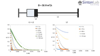
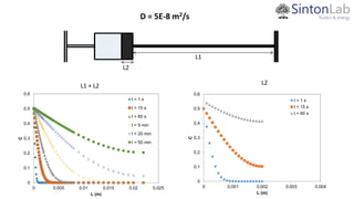
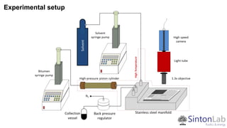
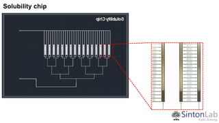
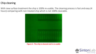
Leverage Microfluidics Methods to Measure Relevant Canadian Oil
Reservoir Fluid Properties
Lab-on-a chip measurement : Solubility
Soheil Talebi
Supervisor : Dr. David Sinton
Department of Mechanical and Industrial Engineering
Oil Sand
a mixture of sand, water, clay and bitumen
Bitumen
Bitumen is oil that is too heavy or thick to flow or be pumped
without being diluted or heated
Bitumen
Crude Oil
Steam Assisted Gravity Drainage (SAGD)
An enhanced oil recovery technology for producing heavy crude oil and bitumen.
Financial and Environmental costs:
- Large quantity of natural gas
- 𝐶𝑂2 Intensive
Improvement on SAGD
- Geometrical improvement : related to well configuration
- Chemical improvement: related to the thermal efficiency, fluid saturation and interfacial tension
- Traditional solvent injection (VAPEX)
- Warm solvent injection
- Warm solvent injection with condensation
- Solvent SAGD
Why using solvent ?
• Reduce CO2 emissions associated with SAGD
• Enhance the oil recovery
• Extend the range of applicability to thinner reservoirs (higher permeability)
However...!
• lack of quantitative assessment of the pore-scale mechanisms active in this process
• Choice of the right solvent mixture and set of operating conditions for a given reservoir (i.e.
pressure, temperature, injection flow rate, and concentration)
Therefore…!
• Reservoir-relevant fluid properties, solubility and viscosity are also essential to inform the reservoir
models operators’ use in decision making and assessment
First phase:
• Recovery factor
• Front velocity
• Emulsion distribution
Second phase:
• Solubility measurement
• Viscosity measurement
Challenges:
• Huge viscosity contrast between bitumen and the solvent (viscosity ratio 107
)
• High operating temperatures necessitating on-chip heater and flow line heating
• Complexity of working with saturated liquid mixtures which requires precise control of relatively low solvent
solubility and diffusion rates
Measurement of Oil swelling factor
Advantages:
o Oil swelling can mobile some of the residual oil so that it can be recovered
o Oil swelling also increases oil saturation and consequently the relative permeability of oil
Motivations:
Microfluidic solubility measurement
High pressure
High Temperature
High accuracy
Small sample
Fast
Other application:
Mass transfer quantification
Bitumen swelling measurement
Light-medium-heavy oil
Asphaltene precipitation
Why Microfluidic ?
Solubility Chip
Bitumen 20*20 (um)
Solvent 100*250 (um)
W
H
Micro PVT cell
250*250 (um)
Bitumen
mainchannel
Solvent
mainchannel
Bitumen
neck
Bit/solv
cell
L1 and V1
L2 and V2
L1 >> L2 ~ 10 L2: Diffusion doesn’t reach the bitumen main channel.
V2 >> V1 ~ 20-25 V1: swelling factor is not affected by the bitumen in the neck.
A2 > A1: boundary condition can be applied to the bit/solv cell.
Solubility Chip
L1
L2
𝜕𝐶
𝜕𝑡
= 𝐷
𝜕2 𝐶
𝜕𝑥2 − 𝑣
𝜕𝐶
𝜕𝑥
𝑣 = 0 𝑛𝑜 𝑐𝑜𝑛𝑣𝑒𝑐𝑡𝑖𝑜𝑛
𝐼. 𝐶: 𝑡 = 0, 𝐶 = 0 𝐵. 𝐶: 𝑡 > 0, 𝑥 = 0 𝐶 = 𝐶𝑖
𝐵. 𝐶: 𝑡 > 0, 𝑥 = 𝐿
𝜕𝐶
𝜕𝑥
= 0
𝐶(𝑥, 𝑡) = 𝐶𝑖 𝑒𝑟𝑓𝑐
𝑥
2 𝐷𝑡
+ 𝑒𝑟𝑓𝑐
2𝐿 − 𝑥
2 𝐷𝑡
W
H
0
0.1
0.2
0.3
0.4
0.5
0.6
0 0.005 0.01 0.015 0.02 0.025
C
L (m)
t = 1 s
t = 15 s
t = 60 s
t = 5 min
t = 20 min
t = 50 min
t = 120 min
0
0.1
0.2
0.3
0.4
0.5
0.6
0 0.001 0.002 0.003 0.004
C
L (m)
t = 1 s
t = 15 s
t = 60 s
t = 5 min
t = 20 min
t = 25 min
t = 120 min
L1 + L2
D = 5E-10 m2/s
L1
L2
L2
0
0.1
0.2
0.3
0.4
0.5
0.6
0 0.005 0.01 0.015 0.02 0.025
C
L (m)
t = 1 s
t = 15 s
t = 60 s
t = 5 min
t = 10 min
t = 50 min
t = 100 min
L1
L2
D = 5E-9 m2/s
L1 + L2 L2
0
0.1
0.2
0.3
0.4
0.5
0.6
0 0.001 0.002 0.003 0.004 0.005 0.006
C
L (m)
t = 1 s
t = 15 s
t = 60 s
t = 5 min
t = 10 min
0
0.1
0.2
0.3
0.4
0.5
0.6
0 0.005 0.01 0.015 0.02 0.025
C
L (m)
t = 1 s
t = 15 s
t = 60 s
t = 5 min
t = 20 min
t = 50 min
L1
L2
D = 5E-8 m2/s
L1 + L2 L2
0
0.1
0.2
0.3
0.4
0.5
0.6
0 0.001 0.002 0.003 0.004
C
L (m)
t = 1 s
t = 15 s
t = 60 s
Experimental setup
Solubility chip
Non-treated Surface Treated Surface (Silanized)
Filling
• The inner surface of the chip has been Silanized to make the surface non-wet to bitumen.
• The following procedure is done to proof the swelled bitumen is due to the solubility of the
bitumen not because of the pressure of the propane.
o The chip is filled with bitumen at 65 C. The chip is maintained at this temperature for about 24 hours.
There is no bitumen wall. (Figure 1, 2)
Figure 1 : t = 1 hours Figure 2 : t = 24 hours
BitumenDirection
BitumenDirection
PropaneDirection
PropaneDirection
Proof of concept
o Nitrogen is injected into the chip (from the top) at 6, 10, and 20 bar. The effect of pressure
on bitumen has been investigated. (The chip is maintained at 65 C whole time). At 6 and 10
bar there is no sign of change. At 20 bar there is some change on the meniscus and there is
some back flow, however the change is completely different than the effect of swelling.
(Figure 3, 4, 4)
Figure 4 : Nitrogen 10 bar
Time = 60 mins to 120 mins
Figure 5 : Nitrogen at 20 bar
Time = 120 mins to 180 mins
Figure 3 : Nitrogen 6 bar
Time = 0 to 60 mins
1 2 3
4 5 6
7 8 9
10 11 12
13 14 15
16 17 18
19 20 21
Propane @ 7.2 bar Time = 0
Propane @ 7.2 bar Time = 45 mins
Propane @ 7.2 bar Combined images
Top View of PVT cell
Isometric View of PVT cell
Top View of PVT cell
Isometric View of PVT cell
Image analysis – Curve Fitting
y = 1E-08x3 - 3E-05x2 + 0.0009x + 33.886
R² = 0.9291
0
5
10
15
20
25
30
35
40
45
0 200 400 600 800 1000 1200 1400 1600
Swelling Factor : 1.0469
Chip cleaning
With new surface treatment the chip is 100% re-usable. The cleaning process is fast and easy (4
hours) comparing with non-treated chip which is not 100% cleanable.
Figure 6 : The chip is cleaned and is re-usable
Thanks

Soheil Talebi General Talk Sep 2016

  • 1.
    Leverage Microfluidics Methodsto Measure Relevant Canadian Oil Reservoir Fluid Properties Lab-on-a chip measurement : Solubility Soheil Talebi Supervisor : Dr. David Sinton Department of Mechanical and Industrial Engineering
  • 2.
    Oil Sand a mixtureof sand, water, clay and bitumen Bitumen Bitumen is oil that is too heavy or thick to flow or be pumped without being diluted or heated Bitumen Crude Oil
  • 3.
    Steam Assisted GravityDrainage (SAGD) An enhanced oil recovery technology for producing heavy crude oil and bitumen. Financial and Environmental costs: - Large quantity of natural gas - 𝐶𝑂2 Intensive
  • 4.
    Improvement on SAGD -Geometrical improvement : related to well configuration - Chemical improvement: related to the thermal efficiency, fluid saturation and interfacial tension - Traditional solvent injection (VAPEX) - Warm solvent injection - Warm solvent injection with condensation - Solvent SAGD
  • 5.
    Why using solvent? • Reduce CO2 emissions associated with SAGD • Enhance the oil recovery • Extend the range of applicability to thinner reservoirs (higher permeability) However...! • lack of quantitative assessment of the pore-scale mechanisms active in this process • Choice of the right solvent mixture and set of operating conditions for a given reservoir (i.e. pressure, temperature, injection flow rate, and concentration) Therefore…! • Reservoir-relevant fluid properties, solubility and viscosity are also essential to inform the reservoir models operators’ use in decision making and assessment
  • 6.
    First phase: • Recoveryfactor • Front velocity • Emulsion distribution Second phase: • Solubility measurement • Viscosity measurement Challenges: • Huge viscosity contrast between bitumen and the solvent (viscosity ratio 107 ) • High operating temperatures necessitating on-chip heater and flow line heating • Complexity of working with saturated liquid mixtures which requires precise control of relatively low solvent solubility and diffusion rates
  • 7.
    Measurement of Oilswelling factor Advantages: o Oil swelling can mobile some of the residual oil so that it can be recovered o Oil swelling also increases oil saturation and consequently the relative permeability of oil
  • 8.
    Motivations: Microfluidic solubility measurement Highpressure High Temperature High accuracy Small sample Fast Other application: Mass transfer quantification Bitumen swelling measurement Light-medium-heavy oil Asphaltene precipitation Why Microfluidic ?
  • 9.
    Solubility Chip Bitumen 20*20(um) Solvent 100*250 (um) W H Micro PVT cell 250*250 (um)
  • 10.
    Bitumen mainchannel Solvent mainchannel Bitumen neck Bit/solv cell L1 and V1 L2and V2 L1 >> L2 ~ 10 L2: Diffusion doesn’t reach the bitumen main channel. V2 >> V1 ~ 20-25 V1: swelling factor is not affected by the bitumen in the neck. A2 > A1: boundary condition can be applied to the bit/solv cell. Solubility Chip
  • 11.
    L1 L2 𝜕𝐶 𝜕𝑡 = 𝐷 𝜕2 𝐶 𝜕𝑥2− 𝑣 𝜕𝐶 𝜕𝑥 𝑣 = 0 𝑛𝑜 𝑐𝑜𝑛𝑣𝑒𝑐𝑡𝑖𝑜𝑛 𝐼. 𝐶: 𝑡 = 0, 𝐶 = 0 𝐵. 𝐶: 𝑡 > 0, 𝑥 = 0 𝐶 = 𝐶𝑖 𝐵. 𝐶: 𝑡 > 0, 𝑥 = 𝐿 𝜕𝐶 𝜕𝑥 = 0 𝐶(𝑥, 𝑡) = 𝐶𝑖 𝑒𝑟𝑓𝑐 𝑥 2 𝐷𝑡 + 𝑒𝑟𝑓𝑐 2𝐿 − 𝑥 2 𝐷𝑡 W H
  • 12.
    0 0.1 0.2 0.3 0.4 0.5 0.6 0 0.005 0.010.015 0.02 0.025 C L (m) t = 1 s t = 15 s t = 60 s t = 5 min t = 20 min t = 50 min t = 120 min 0 0.1 0.2 0.3 0.4 0.5 0.6 0 0.001 0.002 0.003 0.004 C L (m) t = 1 s t = 15 s t = 60 s t = 5 min t = 20 min t = 25 min t = 120 min L1 + L2 D = 5E-10 m2/s L1 L2 L2
  • 13.
    0 0.1 0.2 0.3 0.4 0.5 0.6 0 0.005 0.010.015 0.02 0.025 C L (m) t = 1 s t = 15 s t = 60 s t = 5 min t = 10 min t = 50 min t = 100 min L1 L2 D = 5E-9 m2/s L1 + L2 L2 0 0.1 0.2 0.3 0.4 0.5 0.6 0 0.001 0.002 0.003 0.004 0.005 0.006 C L (m) t = 1 s t = 15 s t = 60 s t = 5 min t = 10 min
  • 14.
    0 0.1 0.2 0.3 0.4 0.5 0.6 0 0.005 0.010.015 0.02 0.025 C L (m) t = 1 s t = 15 s t = 60 s t = 5 min t = 20 min t = 50 min L1 L2 D = 5E-8 m2/s L1 + L2 L2 0 0.1 0.2 0.3 0.4 0.5 0.6 0 0.001 0.002 0.003 0.004 C L (m) t = 1 s t = 15 s t = 60 s
  • 15.
  • 16.
  • 17.
    Non-treated Surface TreatedSurface (Silanized) Filling
  • 18.
    • The innersurface of the chip has been Silanized to make the surface non-wet to bitumen. • The following procedure is done to proof the swelled bitumen is due to the solubility of the bitumen not because of the pressure of the propane. o The chip is filled with bitumen at 65 C. The chip is maintained at this temperature for about 24 hours. There is no bitumen wall. (Figure 1, 2) Figure 1 : t = 1 hours Figure 2 : t = 24 hours BitumenDirection BitumenDirection PropaneDirection PropaneDirection Proof of concept
  • 19.
    o Nitrogen isinjected into the chip (from the top) at 6, 10, and 20 bar. The effect of pressure on bitumen has been investigated. (The chip is maintained at 65 C whole time). At 6 and 10 bar there is no sign of change. At 20 bar there is some change on the meniscus and there is some back flow, however the change is completely different than the effect of swelling. (Figure 3, 4, 4) Figure 4 : Nitrogen 10 bar Time = 60 mins to 120 mins Figure 5 : Nitrogen at 20 bar Time = 120 mins to 180 mins Figure 3 : Nitrogen 6 bar Time = 0 to 60 mins
  • 20.
    1 2 3 45 6 7 8 9 10 11 12 13 14 15 16 17 18 19 20 21
  • 21.
    Propane @ 7.2bar Time = 0 Propane @ 7.2 bar Time = 45 mins Propane @ 7.2 bar Combined images
  • 22.
    Top View ofPVT cell Isometric View of PVT cell
  • 23.
    Top View ofPVT cell Top View of PVT cell Isometric View of PVT cell
  • 24.
    Image analysis –Curve Fitting y = 1E-08x3 - 3E-05x2 + 0.0009x + 33.886 R² = 0.9291 0 5 10 15 20 25 30 35 40 45 0 200 400 600 800 1000 1200 1400 1600 Swelling Factor : 1.0469
  • 25.
    Chip cleaning With newsurface treatment the chip is 100% re-usable. The cleaning process is fast and easy (4 hours) comparing with non-treated chip which is not 100% cleanable. Figure 6 : The chip is cleaned and is re-usable
  • 26.

Editor's Notes

  • #3 The estimated worldwide deposits of oil are more than 2 trillion barrels (320 billion cubic metres);[3] the estimates include deposits that have not been discovered. Proven reserves of bitumen contain approximately 100 billion barrels,[4] and 70.8%, are in Alberta, Canada.[1] Canada has most of the world's supply of natural asphalt/bitumen, covering 140,000 square kilometres[61] (an area larger than England), giving it the second-largest proven oil reserves in the world. 
  • #4 Steam Assisted Gravity Drainage (SAGD; "Sag-D") is an enhanced oil recovery technology for producing heavy crude oil and bitumen. It is an advanced form of steam stimulation in which a pair of horizontal wells is drilled into the oil reservoir, one a few metres above the other. High pressure steam is continuously injected into the upper wellbore to heat the oil and reduce its viscosity, causing the heated oil to drain into the lower wellbore, where it is pumped out. Dr. Roger Butler, engineer at Imperial Oil from 1955 to 1982, invented the steam assisted gravity drainage (SAGD) in the 1970s
  • #5 i. (VAPEX) in which solvent remains in vapour phase at reservoir conditions. Solvent vapour diffuses to the adjacent bitumen at the edge of the solvent chamber and dilutes and mobilize the bitumen. ii. Warm solvent injection in which the solvent is pre-heated. The viscosity of Athabasca bitumen reduces by a factor of 100 when it warms by 25- 30°C. At elevated temperatures, diffusion of solvent is faster and bitumen flows more readily, however, solvent solubility is lower. Thus the effectiveness of this process depends on a combination of factors. iii. Warm solvent injection w/condensation in which solvent is injected in the vapour state and then condenses within the reservoir. By employing the latent heat of condensation of the solvent, this process is conceptually similar to SAGD. This mode is the first focus of the project. iv. Solvent-SAGD in which the solvent is co-injected with steam, similar to the traditional SAGD process. This mode is effectively a SAGD process with a solvent additive, and will be the second focus of the project.
  • #6  Although solvent based processes offer potential financial and environmental advantages over conventional SAGD, a lack of quantitative performance assessment and a lack of relevant fluid property data are barriers to adoption. Specifically a lack of understanding in solvent/bitumen and solvent/steam/bitumen interactions and the associated pore-scale physics is a major source of uncertainty in solvent-injection and solvent-SAGD operation design and development.