Download to read offline


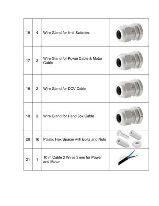
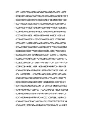
![CONTROLLER COMPONENT
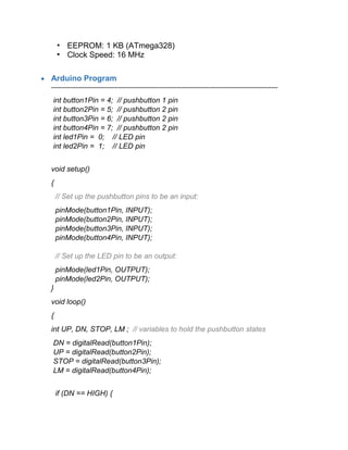
No Qty Component Image
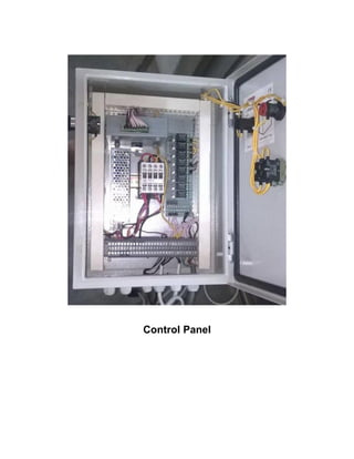
1 1 Electric Control panel box 30 x 40 cm
2 2 Plastic box 115, 75, 38 mm L, W, H
3 1
8 Output Relay Module
[KIT.8RELAY]
4 2 Limit Switch
5 1 Arduino UNO Circuit
6 1
Power Supply 12 VDC
[KIT.SMPS.12V.3A]
7 1 3SC8 AC contactor 35 A
8 8 Pluggable Terminal Block 2 Pin](https://image.slidesharecdn.com/pressmachinecontroller-160708072431/85/Press-machine-controller-6-320.jpg)
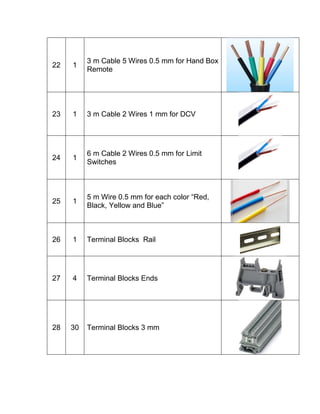
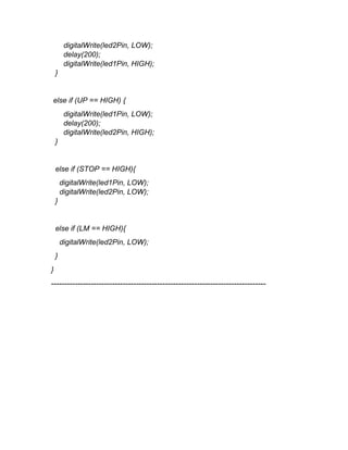
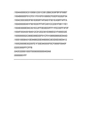
![ 8 Output Relay Module (Enabled with 3 ~ 12 Volts) [KIT.8RELAY]
Features:
1) Operating with 12VDC(300mA).
2) Open each relay with 3 ~ 12 volts ( Can be directly connected to
Microcontrollers , Arduino Boards or PC port).
3) Output of each relay can be used for current up to 7A (at 28Vdc or
at 240Vac).
4) Each relay with LED illuminate when the relay is enabled.
5) Dimensions: 100 x 52 mm
6) Easy to connect the wires through PCB screw terminal blocks
(Enlarge the photo to see it clearly).
Limit switch
Dual circuit snap-action limit switch](https://image.slidesharecdn.com/pressmachinecontroller-160708072431/85/Press-machine-controller-11-320.jpg)
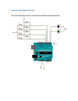

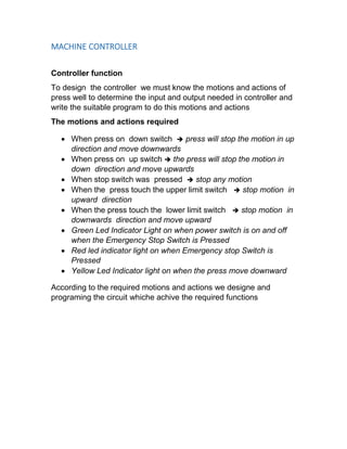
The document describes the design of a machine controller. It includes: 1) The required motions and actions of the press that the controller must perform, such as stopping or changing direction when various switches are pressed. 2) The components needed for the controller, including an Arduino board, relays, switches, and indicators. 3) The circuit diagram and Arduino program for controlling the press motions based on input from the switches.


![[Deck] What's New in Spark-Iceberg Integration via DSV2.pptx](https://cdn.slidesharecdn.com/ss_thumbnails/deckwhatsnewinspark-icebergintegrationviadsv2-260210005337-25955b12-thumbnail.jpg?width=640&height=640&fit=bounds)

