Download to read offline


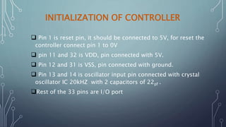


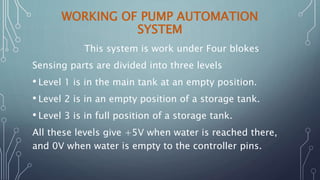
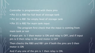
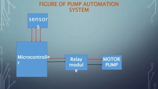
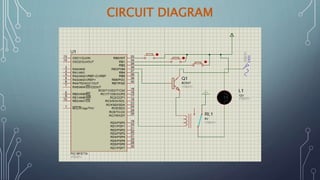


This project involves automating a motor pump system using a PIC16F77A microcontroller. The system uses three water level sensors to detect the level in the main tank and storage tank. When the main tank level is low, the motor turns on to pump water into the storage tank. When the storage tank is full, the motor turns off. The PIC microcontroller is programmed using C language and controls a relay module to switch the motor on and off based on the sensor readings. The system aims to automatically refill the storage tank when needed without manual intervention.


![Water level indicator [autosaved]](https://cdn.slidesharecdn.com/ss_thumbnails/waterlevelindicatorautosaved-151215123305-thumbnail.jpg?width=640&height=640&fit=bounds)


