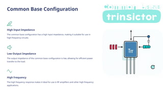
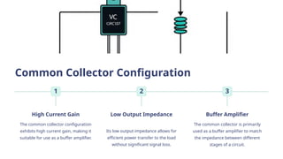
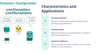
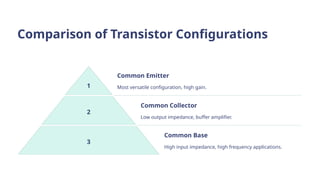
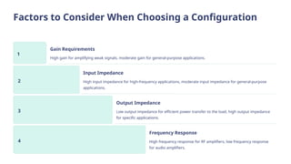
Transistor Configurations:
A Deep Dive
This presentation will explore the different types of transistor
configurations, outlining their characteristics, applications, and practical
considerations. We will dive into the details of each configuration,
providing a comprehensive understanding of how they function and
where they are best used. Get ready to unlock the secrets of transistor
circuits!
by Keval Shah
Introduction to Transistors
Semiconductor Devices
Transistors are essential
semiconductor devices that act as
electronic switches or amplifiers. They
are commonly used in electronic
circuits for a wide range of
applications.
Three Terminals
Transistors consist of three terminals:
the base, collector, and emitter. These
terminals interact with each other to
control the flow of current.
Amplification and Switching
Transistors can amplify small
electrical signals or act as switches to
control the flow of larger currents.
Common Transistor
Configurations
1 Common Emitter
The most common
configuration, providing
high gain and moderate
input impedance.
2 Common Base
Offers high input
impedance and low output
impedance, used for high-
frequency applications.
3 Common Collector
Known for high current gain and low output impedance,
primarily used as a buffer amplifier.
Common Emitter Configuration
High Gain
This configuration provides a high
current gain, making it suitable for
amplifying weak signals.
Moderate Input
Impedance
The input impedance of the
common emitter is neither too high
nor too low, providing a good
balance for various applications.
Widely Used
Its versatility and high gain make it
the most commonly used
configuration in amplifiers,
oscillators, and other circuits.
Common Base Configuration
High Input Impedance
The common base configuration has a high input impedance, making it suitable for use in
high-frequency circuits.
Low Output Impedance
The output impedance of the common base configuration is low, allowing for efficient power
transfer to the load.
High Frequency
The high frequency response makes it ideal for use in RF amplifiers and other high-frequency
applications.
Common Collector Configuration
1
High Current Gain
The common collector configuration
exhibits high current gain, making it
suitable for use as a buffer amplifier.
2
Low Output Impedance
Its low output impedance allows for
efficient power transfer to the load
without significant signal loss.
3
Buffer Amplifier
The common collector is primarily
used as a buffer amplifier to match
the impedance between different
stages of a circuit.
Characteristics and
Applications
Common Emitter
High gain, moderate input impedance, widely used for
general-purpose amplification.
Common Base
High input impedance, low output impedance, suitable for
high-frequency applications.
Common Collector
High current gain, low output impedance, used as a buffer
amplifier to match impedance.
Comparison of Transistor Configurations
1
Common Emitter
Most versatile configuration, high gain.
2
Common Collector
Low output impedance, buffer amplifier.
3
Common Base
High input impedance, high frequency applications.
Factors to Consider When Choosing a Configuration
1
Gain Requirements
High gain for amplifying weak signals, moderate gain for general-purpose applications.
2
Input Impedance
High input impedance for high-frequency applications, moderate input impedance for general-purpose
applications.
3
Output Impedance
Low output impedance for efficient power transfer to the load, high output impedance
for specific applications.
4
Frequency Response
High frequency response for RF amplifiers, low frequency response
for audio amplifiers.
Practical Considerations and
Limitations
1
Power Dissipation
Transistors can generate heat during operation, necessitating heat sinks for proper thermal management.
2
Signal Distortion
Non-linearity in transistor characteristics can introduce signal distortion, especially at high frequencies.
3
Operating Range
Transistors have specific operating ranges for voltage, current, and frequency, which must be respected.
Made By :-
Keval Shah :- (246470307043)
Kavan Dhivare :- (246470307041)
Hitarth Koshiya :- (246470307044)
Pal Kevadiya :- (246470307042)
Yash Jethva :- (246470307032)

Different types of Transistor Configurations.pptx

  • 1.
    Transistor Configurations: A DeepDive This presentation will explore the different types of transistor configurations, outlining their characteristics, applications, and practical considerations. We will dive into the details of each configuration, providing a comprehensive understanding of how they function and where they are best used. Get ready to unlock the secrets of transistor circuits! by Keval Shah
  • 2.
    Introduction to Transistors SemiconductorDevices Transistors are essential semiconductor devices that act as electronic switches or amplifiers. They are commonly used in electronic circuits for a wide range of applications. Three Terminals Transistors consist of three terminals: the base, collector, and emitter. These terminals interact with each other to control the flow of current. Amplification and Switching Transistors can amplify small electrical signals or act as switches to control the flow of larger currents.
  • 3.
    Common Transistor Configurations 1 CommonEmitter The most common configuration, providing high gain and moderate input impedance. 2 Common Base Offers high input impedance and low output impedance, used for high- frequency applications. 3 Common Collector Known for high current gain and low output impedance, primarily used as a buffer amplifier.
  • 4.
    Common Emitter Configuration HighGain This configuration provides a high current gain, making it suitable for amplifying weak signals. Moderate Input Impedance The input impedance of the common emitter is neither too high nor too low, providing a good balance for various applications. Widely Used Its versatility and high gain make it the most commonly used configuration in amplifiers, oscillators, and other circuits.
  • 5.
    Common Base Configuration HighInput Impedance The common base configuration has a high input impedance, making it suitable for use in high-frequency circuits. Low Output Impedance The output impedance of the common base configuration is low, allowing for efficient power transfer to the load. High Frequency The high frequency response makes it ideal for use in RF amplifiers and other high-frequency applications.
  • 6.
    Common Collector Configuration 1 HighCurrent Gain The common collector configuration exhibits high current gain, making it suitable for use as a buffer amplifier. 2 Low Output Impedance Its low output impedance allows for efficient power transfer to the load without significant signal loss. 3 Buffer Amplifier The common collector is primarily used as a buffer amplifier to match the impedance between different stages of a circuit.
  • 7.
    Characteristics and Applications Common Emitter Highgain, moderate input impedance, widely used for general-purpose amplification. Common Base High input impedance, low output impedance, suitable for high-frequency applications. Common Collector High current gain, low output impedance, used as a buffer amplifier to match impedance.
  • 8.
    Comparison of TransistorConfigurations 1 Common Emitter Most versatile configuration, high gain. 2 Common Collector Low output impedance, buffer amplifier. 3 Common Base High input impedance, high frequency applications.
  • 9.
    Factors to ConsiderWhen Choosing a Configuration 1 Gain Requirements High gain for amplifying weak signals, moderate gain for general-purpose applications. 2 Input Impedance High input impedance for high-frequency applications, moderate input impedance for general-purpose applications. 3 Output Impedance Low output impedance for efficient power transfer to the load, high output impedance for specific applications. 4 Frequency Response High frequency response for RF amplifiers, low frequency response for audio amplifiers.
  • 10.
    Practical Considerations and Limitations 1 PowerDissipation Transistors can generate heat during operation, necessitating heat sinks for proper thermal management. 2 Signal Distortion Non-linearity in transistor characteristics can introduce signal distortion, especially at high frequencies. 3 Operating Range Transistors have specific operating ranges for voltage, current, and frequency, which must be respected.
  • 11.
    Made By :- KevalShah :- (246470307043) Kavan Dhivare :- (246470307041) Hitarth Koshiya :- (246470307044) Pal Kevadiya :- (246470307042) Yash Jethva :- (246470307032)