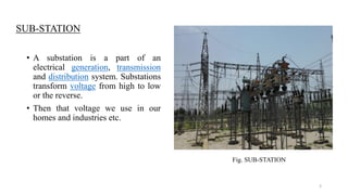
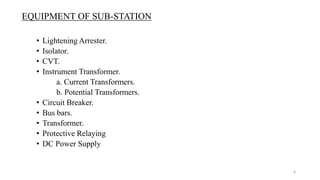
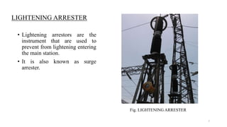
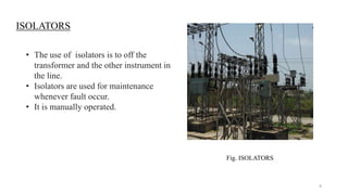
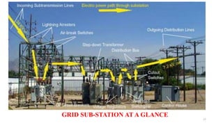
GUIDED BY:-
Mr. Deepak Somani
Asst. Prof. EE
PRESENTED BY:-
Ravi kant
Roll no. :-12ECOEE020
A
TRAINING SEMINAR
ON
“GRID SUB-STATION”
SESSION 2015-16
Bachelor of Technology
In
Electrical Engineering
1
CONTENTS
SUBSTATION.
TYPES OF SUB-STATION.
SINGLE LINE DIAGRAM.
EQUIPMENT.
• Lightening Arrester.
• Isolator.
• CVT.
• Instrument Transformer.
a. Current Transformers.
b. Potential Transformers.
• Circuit Breaker.
• Bus bars.
• Transformer.
• Protective Relaying.
• DC Power Supply.
2
SUB-STATION
• A substation is a part of an
electrical generation, transmission
and distribution system. Substations
transform voltage from high to low
or the reverse.
• Then that voltage we use in our
homes and industries etc.
Fig. SUB-STATION
3
CLASSIFICATION OF SUB-STATION
• ACCORDING TO SERVICE REQUIRMENT.
a) Transformer sub-station.
b) Switching sub-station.
c) Power factor correction sub-station.
d) Frequency changer sub-station.
e) Converting sub-station.
• ACCORDING TO CONSTRUCTIONAL FEATURE.
a) Indoor sub-station.
b) Outdoor sub-station.
c) Underground sub-station.
d) Pole-mounted sub-station.
4
SINGLE LINE DIAGRAM
5
EQUIPMENT OF SUB-STATION
• Lightening Arrester.
• Isolator.
• CVT.
• Instrument Transformer.
a. Current Transformers.
b. Potential Transformers.
• Circuit Breaker.
• Bus bars.
• Transformer.
• Protective Relaying
• DC Power Supply
6
LIGHTENING ARRESTER
• Lightening arrestors are the
instrument that are used to
prevent from lightening entering
the main station.
• It is also known as surge
arrester.
Fig. LIGHTENING ARRESTER
7
ISOLATORS
• The use of isolators is to off the
transformer and the other instrument in
the line.
• Isolators are used for maintenance
whenever fault occur.
• It is manually operated.
Fig. ISOLATORS
8
CVT(CAPACITOR VOLTAGE TRANSFORMER)
• A CVT is a transformer used
in GSS to step-down extra
high voltage and provide low
voltage either for
measurement or to operate a
protective relay.
Fig. CAPACITOR VOLTAGE TRANSFORMER
9
BUSBAR
• BUSBAR is a term we use
for a main bar or conductor
carrying electric current to
many connection.
Fig. BUSBAR
10
INSTRUMENT TRANSFORMER
• Current transformers are basically
used to take the readings of the
currents entering in the substation.
• The other uses of this CT.
a) Distance Protection.
b) Backup Protection.
c) Measurement.
Fig. INSTRUMENT TRANSFORMER
CURRENT TRANSFORMER
11
• The potential transformer uses for
Measurement and Protection.
• The main use of potential transformer
is to measure the voltage through the
Busbar.
• There are two main parts in it.
a) Measurement.
b) Protection.
POTENTIAL TRANSFORMER
Fig. POTENTIAL TRANSFORMER
12
PROTECTIVE RELAYS
• Relay is a device which sense the
fault and send message signal to
circuit breaker to trip the coil.
• It used for transformer protection.
Fig. PROTECTIVE RELAYS
13
CIRCUIT BREAKER
• A circuit breaker is used to receive
the fault message signal from the
relay and trip the coil.
TYPES:-
a) AIR CIRCUIT BREAKER.
b) OIL CIRCUIT BREAKER.
c) VACCUM CIRCUIT BREAKER.
d) SF6 CIRCUIT BREAKER.
Fig. CIRCUIT BREAKER
14
TRANSFORMERS
• Transformer is a static device by
which Transform AC electrical
power from one voltage level into
other level by keeping same
frequency.
• Transformer used in GSS is
called Power Transformer.
Fig. TRANSFORMERS
15
DC POWER SUPPLY
• DC power supply is used for
operate Circuit Breaker and
control room operation.
• 110V dc power supply is
used.
Fig. DC POWER SUPPLY
16
GRID SUB-STATION AT A GLANCE
17
18

GSS ppt

  • 1.
    GUIDED BY:- Mr. DeepakSomani Asst. Prof. EE PRESENTED BY:- Ravi kant Roll no. :-12ECOEE020 A TRAINING SEMINAR ON “GRID SUB-STATION” SESSION 2015-16 Bachelor of Technology In Electrical Engineering 1
  • 2.
    CONTENTS SUBSTATION. TYPES OF SUB-STATION. SINGLELINE DIAGRAM. EQUIPMENT. • Lightening Arrester. • Isolator. • CVT. • Instrument Transformer. a. Current Transformers. b. Potential Transformers. • Circuit Breaker. • Bus bars. • Transformer. • Protective Relaying. • DC Power Supply. 2
  • 3.
    SUB-STATION • A substationis a part of an electrical generation, transmission and distribution system. Substations transform voltage from high to low or the reverse. • Then that voltage we use in our homes and industries etc. Fig. SUB-STATION 3
  • 4.
    CLASSIFICATION OF SUB-STATION •ACCORDING TO SERVICE REQUIRMENT. a) Transformer sub-station. b) Switching sub-station. c) Power factor correction sub-station. d) Frequency changer sub-station. e) Converting sub-station. • ACCORDING TO CONSTRUCTIONAL FEATURE. a) Indoor sub-station. b) Outdoor sub-station. c) Underground sub-station. d) Pole-mounted sub-station. 4
  • 5.
  • 6.
    EQUIPMENT OF SUB-STATION •Lightening Arrester. • Isolator. • CVT. • Instrument Transformer. a. Current Transformers. b. Potential Transformers. • Circuit Breaker. • Bus bars. • Transformer. • Protective Relaying • DC Power Supply 6
  • 7.
    LIGHTENING ARRESTER • Lighteningarrestors are the instrument that are used to prevent from lightening entering the main station. • It is also known as surge arrester. Fig. LIGHTENING ARRESTER 7
  • 8.
    ISOLATORS • The useof isolators is to off the transformer and the other instrument in the line. • Isolators are used for maintenance whenever fault occur. • It is manually operated. Fig. ISOLATORS 8
  • 9.
    CVT(CAPACITOR VOLTAGE TRANSFORMER) •A CVT is a transformer used in GSS to step-down extra high voltage and provide low voltage either for measurement or to operate a protective relay. Fig. CAPACITOR VOLTAGE TRANSFORMER 9
  • 10.
    BUSBAR • BUSBAR isa term we use for a main bar or conductor carrying electric current to many connection. Fig. BUSBAR 10
  • 11.
    INSTRUMENT TRANSFORMER • Currenttransformers are basically used to take the readings of the currents entering in the substation. • The other uses of this CT. a) Distance Protection. b) Backup Protection. c) Measurement. Fig. INSTRUMENT TRANSFORMER CURRENT TRANSFORMER 11
  • 12.
    • The potentialtransformer uses for Measurement and Protection. • The main use of potential transformer is to measure the voltage through the Busbar. • There are two main parts in it. a) Measurement. b) Protection. POTENTIAL TRANSFORMER Fig. POTENTIAL TRANSFORMER 12
  • 13.
    PROTECTIVE RELAYS • Relayis a device which sense the fault and send message signal to circuit breaker to trip the coil. • It used for transformer protection. Fig. PROTECTIVE RELAYS 13
  • 14.
    CIRCUIT BREAKER • Acircuit breaker is used to receive the fault message signal from the relay and trip the coil. TYPES:- a) AIR CIRCUIT BREAKER. b) OIL CIRCUIT BREAKER. c) VACCUM CIRCUIT BREAKER. d) SF6 CIRCUIT BREAKER. Fig. CIRCUIT BREAKER 14
  • 15.
    TRANSFORMERS • Transformer isa static device by which Transform AC electrical power from one voltage level into other level by keeping same frequency. • Transformer used in GSS is called Power Transformer. Fig. TRANSFORMERS 15
  • 16.
    DC POWER SUPPLY •DC power supply is used for operate Circuit Breaker and control room operation. • 110V dc power supply is used. Fig. DC POWER SUPPLY 16
  • 17.
  • 18.