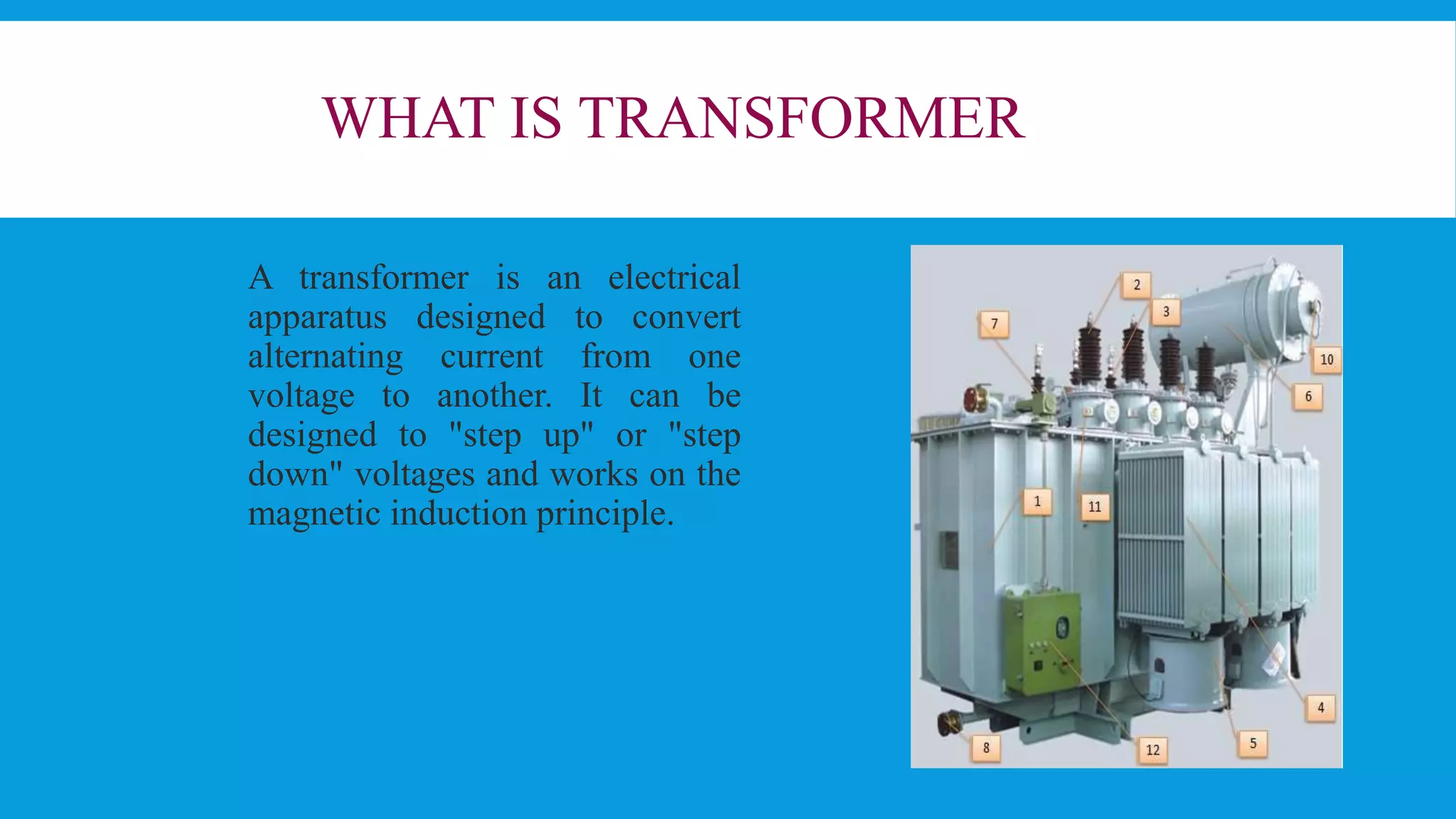
R.R INSTITUTE OF MORDERN POLYTECHNIC
LUCKNOW
PRESENTATION
ON
SUMMER TRAINING FROM UPPCL
Jankipuram, Lucknow (U.P.)
33/11 KV Substation
PRESENTED BY:- SUBMITTED TO:-
Satis Yadav Mr. Mahtabul Haque
E.NO : E20271432800040 (HOD OF EE )
CONTENTS
 SUBSTATION
 SINGLE LINE DIAGRAM
 CONCEPT OF BUS
 EQUIPMENTS ATBUS STATION
 WHATISTRANSFORMER
 PARTSOF TRANSFORMER
 TESTING IN TRANSFORMER
 CIRCUIT BREAKER
 ISOLATOR
 RELAY
 INSULATOR
 LIGHTNINGARRESTOR
 CURRENT TRANSFORMERAND POTENTIALTRNSFORMER
 REFERENCES
WHAT IS A SUBSTATION
A substation is a part of an electrical generation, transmission, and
distribution system. Substations transform voltage from high to
low, or the reverse, or perform any of several other important
functions. Electric power may flow through several substations
between generating plant and consumer, and its voltage may
change in several steps.
SINGLE LINE DIAGRAM
Single line diagram do not show the exact electrical
connection of the circuit. As the name suggests, SLDs use a
single line to represent all three phases. They show the
relative electrical interconnections of generators,
transformers, transmission and distribution lines, loads,
circuit breakers, etc., used in assembling the power
system. The amount of information included in an SLD
depends on the purpose for which the diagram is used.
CONCEPT OF BUS
1.The concept of bus is Same as
the concept of a node in an
electrical circuit.
2. There is one bus for each
phase.
3.Shown in SLDs as lines
connecting equipment to
the buses.
4.Mad of aluminum or copper
bars or pipes and can be several
meters long.
5.The impedance of buses is
very low, practically zero, so
electrically the whole bus is at
the same potential.
EQUIPMENTS AT THE SUBSTATION
MAJOR EQUIPMENT:
1. POWER TRANSFORMERS
MEASURING INSTRUMENTS:
1. CURRENTTRANSFORMER
2. POTENTIALTRANSFORMER
PROTECTING DEVICES:
1. ISOLATOR
2. CIRCUIT BREAKER
3. RELA
Y
4. LIGHTNING ARRESTOR
WHAT IS TRANSFORMER
A transformer is an electrical
apparatus designed to convert
alternating current from one
voltage to another. It can be
designed to "step up" or "step
down" voltages and works on the
magnetic induction principle.
PARTS OF THE TRANSFORMER
1. Transformer Tank
2. High VoltageBushing
3. Low Voltage Bushing
4. Cooling Fins/Radiator
5. Cooling Fans
6. ConservatorTank
7. System GroundTerminal
8. Drain Valve
9. Dehydrating breather
10.Oil
1
1
. T
emperature/Pressure gauges
12.Bushing Current Transformers
13.Control Panel
14.Surge Arresters
CIRCUIT BREAKER
1.The basic functions of circuit breaker is protection, which is
interruption of short-circuit and overload fault currents.
2.High-voltage breakers are nearly always solenoid-operated, with
current sensing protective relays operated through current
transformers.
High-voltage breakers are broadly classified by the medium used
extinguish the arc.
a)Bulk oil
b)Minimum oil
c)Air blast
d)Vacuum
e)SF6
ISOLATORS
It is just like a switch is used to make
sure that an electrical circuit can be
completely de- energized for service or
maintenance.
Difference b/w Isolator and circuit
Breaker
 An isolator is an off load device, whereas Circuit
Breaker is an On load device.
 Isolators are operated manually. Circuit Breakers
are operated automatically.
 Isolators have the low withstand capacity as
compared to that of Circuit Breaker.
RELAY
A protective relay is an
electromechanical
apparatus, often with
more than one coil,
designed to calculate
operating conditions
on an electrical circuit
and trip circuit
breakers when a fault
is detected.
INSULATOR
An electrical insulator is a
material in which the electron
does not flow freely or the atom
of the insulator have tightly
bound electrons whose internal
electric charges do not flow
freely; very little electric current
will flow through it under the
influence of an electric field.
LIGHTNING ARRESTOR
 A lightning arrester is a device
used on electrical power
systems to protect the
insulation and conductors of
the system from the damaging
effects of lightning.
 When a lightning surge travels
along the power line to the
arrester, the current from the
surge is diverted through the
arrestor, in most cases to earth.
CURRENT TRANSFORMER AND POTENTIAL
TRANSFORMER
Current transformers (CT), together
with Potential transformers (PT) are
known as instrument transformers.
A current transformer is a type of
transformer that is used to reduce or
multiply an alternating current. It
produces a current in its secondary which
is proportional to the current in its
primary.
The potential transformer may be defined
as an instrument transformer used for the
transformation of voltage from a higher
value to the lower value.
CT PT
33/11 KV Substation Yard
CONCLUSION
The main function of the substation is to collect the energy transmitted at
high voltage from the generating station and then reduce the voltage to an
appropriate value for local distribution and gives facilities for switching.
33/11 kv Substation is used to step down voltage from 33 kv to 11kv and
the output is connected to feeder for local utility.
substation of rating 33/11kV means, the substation has been designed to
receive 5 MVA of power at 33 kV and it will distribute the same on 11 kV.
Summer_Tranning_satihs[1].pptx

Summer_Tranning_satihs[1].pptx

  • 1.
    R.R INSTITUTE OFMORDERN POLYTECHNIC LUCKNOW PRESENTATION ON SUMMER TRAINING FROM UPPCL Jankipuram, Lucknow (U.P.) 33/11 KV Substation PRESENTED BY:- SUBMITTED TO:- Satis Yadav Mr. Mahtabul Haque E.NO : E20271432800040 (HOD OF EE )
  • 2.
    CONTENTS  SUBSTATION  SINGLELINE DIAGRAM  CONCEPT OF BUS  EQUIPMENTS ATBUS STATION  WHATISTRANSFORMER  PARTSOF TRANSFORMER  TESTING IN TRANSFORMER  CIRCUIT BREAKER  ISOLATOR  RELAY  INSULATOR  LIGHTNINGARRESTOR  CURRENT TRANSFORMERAND POTENTIALTRNSFORMER  REFERENCES
  • 3.
    WHAT IS ASUBSTATION A substation is a part of an electrical generation, transmission, and distribution system. Substations transform voltage from high to low, or the reverse, or perform any of several other important functions. Electric power may flow through several substations between generating plant and consumer, and its voltage may change in several steps.
  • 4.
    SINGLE LINE DIAGRAM Singleline diagram do not show the exact electrical connection of the circuit. As the name suggests, SLDs use a single line to represent all three phases. They show the relative electrical interconnections of generators, transformers, transmission and distribution lines, loads, circuit breakers, etc., used in assembling the power system. The amount of information included in an SLD depends on the purpose for which the diagram is used.
  • 6.
    CONCEPT OF BUS 1.Theconcept of bus is Same as the concept of a node in an electrical circuit. 2. There is one bus for each phase. 3.Shown in SLDs as lines connecting equipment to the buses. 4.Mad of aluminum or copper bars or pipes and can be several meters long. 5.The impedance of buses is very low, practically zero, so electrically the whole bus is at the same potential.
  • 7.
    EQUIPMENTS AT THESUBSTATION MAJOR EQUIPMENT: 1. POWER TRANSFORMERS MEASURING INSTRUMENTS: 1. CURRENTTRANSFORMER 2. POTENTIALTRANSFORMER PROTECTING DEVICES: 1. ISOLATOR 2. CIRCUIT BREAKER 3. RELA Y 4. LIGHTNING ARRESTOR
  • 8.
    WHAT IS TRANSFORMER Atransformer is an electrical apparatus designed to convert alternating current from one voltage to another. It can be designed to "step up" or "step down" voltages and works on the magnetic induction principle.
  • 9.
    PARTS OF THETRANSFORMER 1. Transformer Tank 2. High VoltageBushing 3. Low Voltage Bushing 4. Cooling Fins/Radiator 5. Cooling Fans 6. ConservatorTank 7. System GroundTerminal 8. Drain Valve 9. Dehydrating breather 10.Oil 1 1 . T emperature/Pressure gauges 12.Bushing Current Transformers 13.Control Panel 14.Surge Arresters
  • 11.
    CIRCUIT BREAKER 1.The basicfunctions of circuit breaker is protection, which is interruption of short-circuit and overload fault currents. 2.High-voltage breakers are nearly always solenoid-operated, with current sensing protective relays operated through current transformers. High-voltage breakers are broadly classified by the medium used extinguish the arc. a)Bulk oil b)Minimum oil c)Air blast d)Vacuum e)SF6
  • 12.
    ISOLATORS It is justlike a switch is used to make sure that an electrical circuit can be completely de- energized for service or maintenance. Difference b/w Isolator and circuit Breaker  An isolator is an off load device, whereas Circuit Breaker is an On load device.  Isolators are operated manually. Circuit Breakers are operated automatically.  Isolators have the low withstand capacity as compared to that of Circuit Breaker.
  • 13.
    RELAY A protective relayis an electromechanical apparatus, often with more than one coil, designed to calculate operating conditions on an electrical circuit and trip circuit breakers when a fault is detected.
  • 14.
    INSULATOR An electrical insulatoris a material in which the electron does not flow freely or the atom of the insulator have tightly bound electrons whose internal electric charges do not flow freely; very little electric current will flow through it under the influence of an electric field.
  • 15.
    LIGHTNING ARRESTOR  Alightning arrester is a device used on electrical power systems to protect the insulation and conductors of the system from the damaging effects of lightning.  When a lightning surge travels along the power line to the arrester, the current from the surge is diverted through the arrestor, in most cases to earth.
  • 16.
    CURRENT TRANSFORMER ANDPOTENTIAL TRANSFORMER Current transformers (CT), together with Potential transformers (PT) are known as instrument transformers. A current transformer is a type of transformer that is used to reduce or multiply an alternating current. It produces a current in its secondary which is proportional to the current in its primary. The potential transformer may be defined as an instrument transformer used for the transformation of voltage from a higher value to the lower value. CT PT
  • 18.
  • 19.
    CONCLUSION The main functionof the substation is to collect the energy transmitted at high voltage from the generating station and then reduce the voltage to an appropriate value for local distribution and gives facilities for switching. 33/11 kv Substation is used to step down voltage from 33 kv to 11kv and the output is connected to feeder for local utility. substation of rating 33/11kV means, the substation has been designed to receive 5 MVA of power at 33 kV and it will distribute the same on 11 kV.