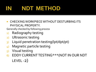
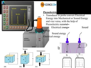
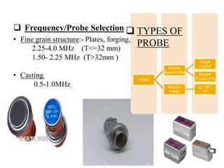
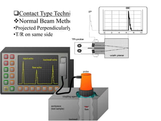
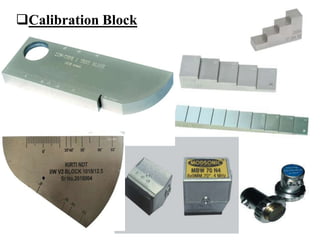
INTRODUCTION ON NDT
BY
NAVENDUAVINASH
IMPLEMENTATION
DESIGNING
PRODUCTION
GAME ON
PLANNING(
MANPOER
MATERIAL
LOCATION
SOURCES
PERMISSIONS
PROCESS
IDEA/ REQUIREMENT
DESTROY
30% PIECES ORPHYSICALLY HARM PIECES
SUPPOSE
100WORKPIECE 30% REQUIREMENT OF INSPECTION
CHECKED BY
**DESTRUCTIVETETSTING**
 CHECKINGWORKPIECE WITHOUT DESTURBING ITS
PHYSICAL PROPERTY.
Generally checked by following process
1) Radiography testing
2) Ultrasonic testing
3) Liquid penetration testing(lpt/dpt/pt)
4) Magnetic particle testing
5) Visual testing
6) EDDY CURRENTTESTING***(NOT IN OUR NDT
LEVEL -2)
 USED FOR CHECKING INNER DEFECT.
 WE CAN SEE DEFECT BY USING FILM.
 CLEAR IMAGE OF INDICATION
X-rays were discovered in 1895 when
Wilhelm Conrad Roentgen observed that a
screen coated with a barium salt fluoresced
when placed near a cathode ray tube.
Roentgen concluded that a form of
penetrating radiation was being emitted by
the cathode ray tube and called the unknown
rays, X-rays.
An x-ray tube requires a source of electrons, a means to accelerate the
electrons, and a target to stop the high-speed electrons.
 USED FOR INNER DEFECT DETECTION
 USE OF ULTRASONIC SOUND FORTESTING
 USE OF ULTRASONIC FREQUENCY
GENERALLY BETWEEN (20KHZTO20MHZ)
 IN CONTACT TYPETESTING(1 MHZ TO 10
MHZ)
 IMMERSIONTYPE(1MHZTO 15 MHZ)
 UT uses high frequency sound
waves (between 0.5 to 20MHz)
 Used for flaw
detection/evaluation, dimensional
measurement, material
characterization, etc.
 Work on the principle of sound
propagation.
 Method is called echo ranging
(device that utilize ultrasonic
waves to estimate and measure
the distance, depth, defects, holes,
etc.)
 A typical pulse-echo UT inspection system consists of several functional units,
such as the pulser/receiver, transducer, and a display device.
 A pulser/receiver is an electronic device that can produce high voltage electrical
pulses. Driven by the pulser, the transducer generates high frequency ultrasonic
energy.
 The sound energy is introduced and through the materials in the form of waves.
When there is a discontinuity (such as a crack) in the wave path, part of the
energy will be reflected back from the flaw surface.
 The reflected wave signal is transformed into an electrical signal by the
transducer and is displayed on a screen. Knowing the velocity of the waves,
travel time can be directly related to the distance that the signal traveled.
 From the signal, information about the reflector location, size, orientation and
other features can sometimes be gained.
Piezoelectric Effect
• Transducer in probe convert Electrical
Energy into Mechanical or Sound Energy
and vice versa, with the help of
Piezoelectric material
Electrical energy Sound
energy
Sound energy
Electrical energy
 Frequency/Probe Selection
• Fine grain structure:- Plates, forging, flat
2.25-4.0 MHz (T<=32 mm)
1.50- 2.25 MHz (T>32mm )
• Casting
0.5-1.0MHz
Probe
Normal
Beam Probe
Single
Crystal
Double
Crystal (TR)
Angular
Probe
45°, 60°,
70°
 TYPES OF
PROBE
Contact Type Techniques
Normal Beam Method
•Projected Perpendicularly
•T/R on same side
Calibration Block
THANKYOU

PPT INTRODUCTION NDT

  • 1.
  • 2.
  • 3.
    DESTROY 30% PIECES ORPHYSICALLYHARM PIECES SUPPOSE 100WORKPIECE 30% REQUIREMENT OF INSPECTION CHECKED BY **DESTRUCTIVETETSTING**
  • 4.
     CHECKINGWORKPIECE WITHOUTDESTURBING ITS PHYSICAL PROPERTY. Generally checked by following process 1) Radiography testing 2) Ultrasonic testing 3) Liquid penetration testing(lpt/dpt/pt) 4) Magnetic particle testing 5) Visual testing 6) EDDY CURRENTTESTING***(NOT IN OUR NDT LEVEL -2)
  • 27.
     USED FORCHECKING INNER DEFECT.  WE CAN SEE DEFECT BY USING FILM.  CLEAR IMAGE OF INDICATION
  • 28.
    X-rays were discoveredin 1895 when Wilhelm Conrad Roentgen observed that a screen coated with a barium salt fluoresced when placed near a cathode ray tube. Roentgen concluded that a form of penetrating radiation was being emitted by the cathode ray tube and called the unknown rays, X-rays.
  • 29.
    An x-ray tuberequires a source of electrons, a means to accelerate the electrons, and a target to stop the high-speed electrons.
  • 41.
     USED FORINNER DEFECT DETECTION  USE OF ULTRASONIC SOUND FORTESTING  USE OF ULTRASONIC FREQUENCY GENERALLY BETWEEN (20KHZTO20MHZ)  IN CONTACT TYPETESTING(1 MHZ TO 10 MHZ)  IMMERSIONTYPE(1MHZTO 15 MHZ)
  • 42.
     UT useshigh frequency sound waves (between 0.5 to 20MHz)  Used for flaw detection/evaluation, dimensional measurement, material characterization, etc.  Work on the principle of sound propagation.  Method is called echo ranging (device that utilize ultrasonic waves to estimate and measure the distance, depth, defects, holes, etc.)
  • 43.
     A typicalpulse-echo UT inspection system consists of several functional units, such as the pulser/receiver, transducer, and a display device.  A pulser/receiver is an electronic device that can produce high voltage electrical pulses. Driven by the pulser, the transducer generates high frequency ultrasonic energy.  The sound energy is introduced and through the materials in the form of waves. When there is a discontinuity (such as a crack) in the wave path, part of the energy will be reflected back from the flaw surface.  The reflected wave signal is transformed into an electrical signal by the transducer and is displayed on a screen. Knowing the velocity of the waves, travel time can be directly related to the distance that the signal traveled.  From the signal, information about the reflector location, size, orientation and other features can sometimes be gained.
  • 44.
    Piezoelectric Effect • Transducerin probe convert Electrical Energy into Mechanical or Sound Energy and vice versa, with the help of Piezoelectric material Electrical energy Sound energy Sound energy Electrical energy
  • 45.
     Frequency/Probe Selection •Fine grain structure:- Plates, forging, flat 2.25-4.0 MHz (T<=32 mm) 1.50- 2.25 MHz (T>32mm ) • Casting 0.5-1.0MHz Probe Normal Beam Probe Single Crystal Double Crystal (TR) Angular Probe 45°, 60°, 70°  TYPES OF PROBE
  • 46.
    Contact Type Techniques NormalBeam Method •Projected Perpendicularly •T/R on same side
  • 47.
  • 61.