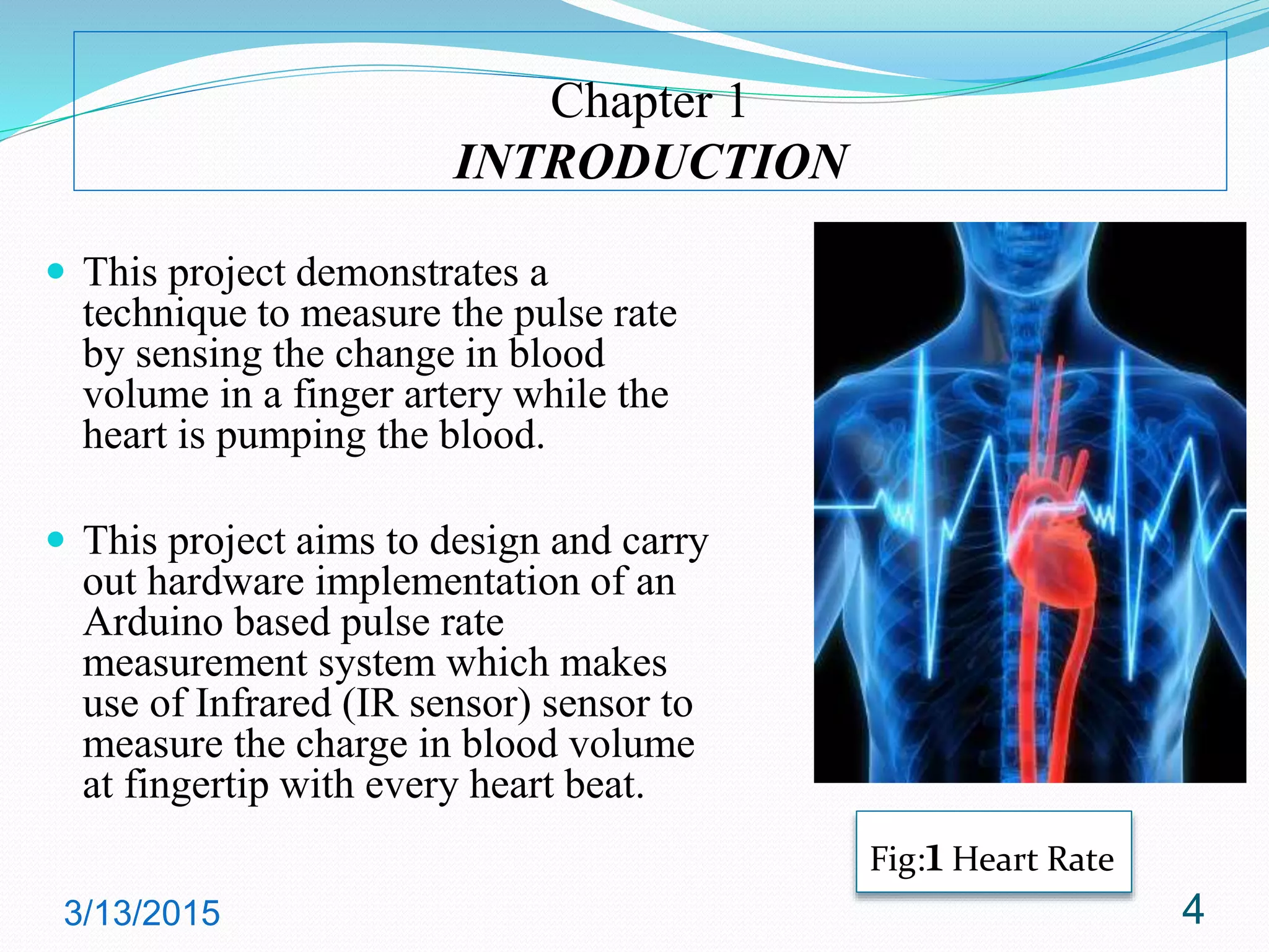
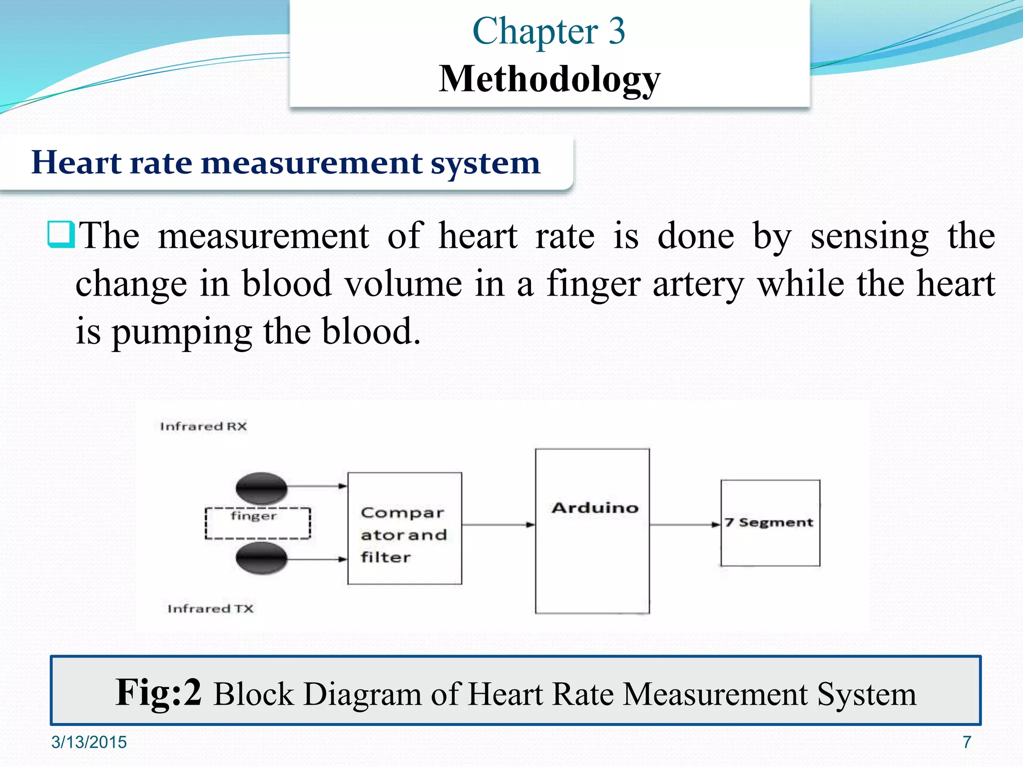
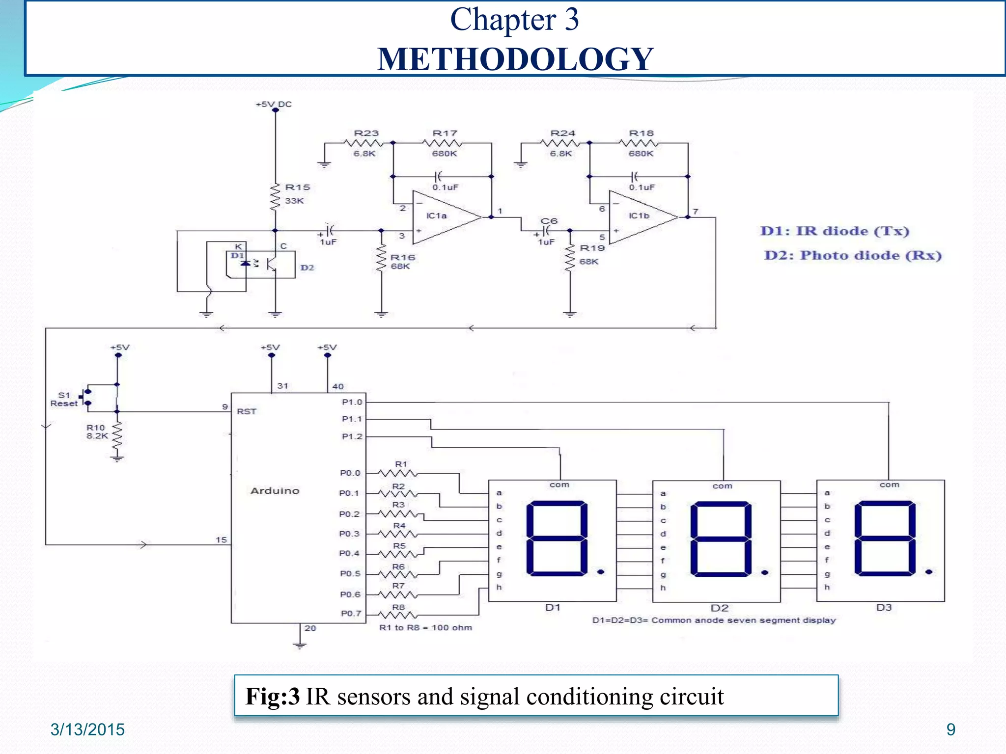
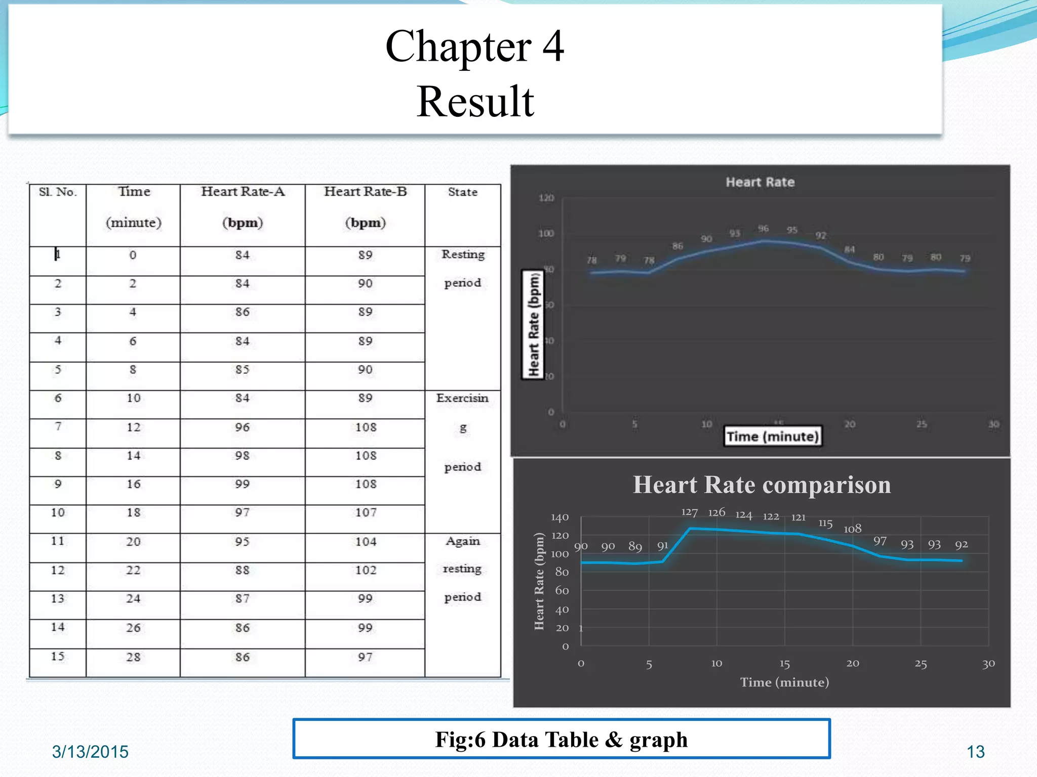
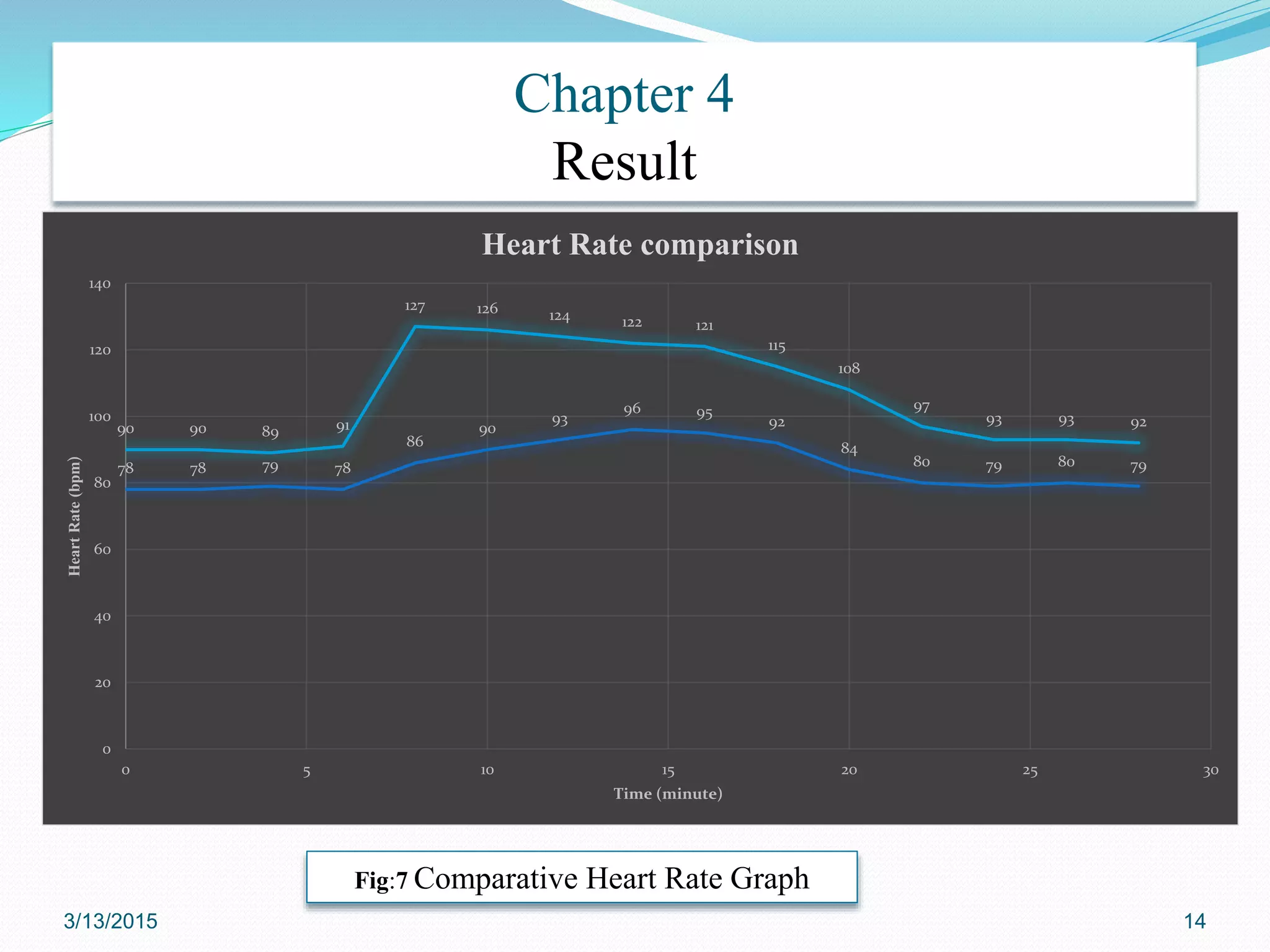
PRESENTED BY
Md. Edris, WUB11/10/27/672
Md. Sobuj, WUB11/10/27/681
S. M. Firoj Mahmud, WUB11/10/27/683
Md. Ataur Rahman Khan, WUB11/10/27/684
SUPERVISED BY
Rumana Tasnim
Lecturer
Department of Mechatronics Engineering
World University of Bangladesh
3/13/2015 2
Contents
Chapter 1: Introduction
Chapter 2: Literature Review
Chapter 3: Methodology
Chapter 4: Result and Discussion
Chapter 5: Conclusion
Chapter 6: Future Recommendation
3/13/2015 3
Chapter 1
INTRODUCTION
 This project demonstrates a
technique to measure the pulse rate
by sensing the change in blood
volume in a finger artery while the
heart is pumping the blood.
 This project aims to design and carry
out hardware implementation of an
Arduino based pulse rate
measurement system which makes
use of Infrared (IR sensor) sensor to
measure the charge in blood volume
at fingertip with every heart beat.
3/13/2015 4
Fig:1 Heart Rate
Objectives
 To design a faster, less time consuming and cost effective
pulse measurement technique.
 To build a simple structured system based on Arduino
and carry out the hardware implementation.
 To analyze the resting heart rate, heart rate during
exercise and recovery heart rate using the technique
Chapter 1
3/13/2015 5
Chapter 2
Literature Review
M. D. Driscoll & Hall, 2000 did another Heart rate measurement which
has been used to detect changes in autonomic function in essential
hypertension, diabetic neuropathy, and sudden infant death.
Tsuji et al., 1994 conducted a study on decreased heart rate variability
(HRV). HRV was found to be a predictor of mortality in elderly subjects.
Nansel et al.,1995 carried out an overall review to examine the
scientific basis of theories which propose that internal diseases are
found to respond in a rapid fashion to therapies.
3/13/2015 6
The measurement of heart rate is done by sensing the
change in blood volume in a finger artery while the heart
is pumping the blood.
Heart rate measurement system
Chapter 3
Methodology
Fig:2 Block Diagram of Heart Rate Measurement System
3/13/2015 7
The Hardware tools used in the project are:
 Arduino R3(UNO)
 IR sensor
 Capacitor
 Resistor
 Diode
 Amplifier (IC MCP602)
 Seven segment display
CHAPTER ONE Chapter 3
METHODOLOGY
3/13/2015 8
Fig:3 IR sensors and signal conditioning circuit
Chapter 3
METHODOLOGY
3/13/2015 9
Chapter 3
METHODOLOGY
 The sensor unit consists of an infrared light-emitting-diode (IR LED)
and a photodiode,
 The IR diode transmits an infrared light into the fingertip (placed over
the sensor unit), and the photodiode senses the portion of the light
that is reflected back.
 The intensity of reflected light depends upon the blood volume inside
the fingertip.
 Heart beat alters the amount of reflected infrared light that can be
detected by photodiode
 The changing blood volume with heartbeat results in a train of pulses
at the output of the photo diode, the magnitude of which is too small
to be detected directly by an Arduino. That’s why a two stage amplifier
has been used.
 The pulses is later counted by the Arduino to determine the heart rate
which is seen in 7 segment display
3/13/2015 10
 Two different students of BMI =23 and BMI=28 were the subjects under test.
 Their resting heart rate, heart rate during exercise and recovery heart rate are
measured over a certain period.
3/13/2015 11
Chapter 3
METHODOLOGY
3/13/2015 12
Chapter 3
METHODOLOGY
FINGER TIP
Fig:5 Complete Hardware setup
Chapter 4
Result
3/13/2015 13
Fig:6 Data Table & graph
1
90 90 89 91
127 126 124 122 121 115 108
97 93 93 92
0
20
40
60
80
100
120
140
0 5 10 15 20 25 30
HeartRate(bpm)
Time (minute)
Heart Rate comparison
3/13/2015 14
Chapter 4
Result
Fig:7 Comparative Heart Rate Graph
78 78 79 78
86
90
93
96 95
92
84
80 79 80 79
90 90 89 91
127 126 124 122 121
115
108
97
93 93 92
0
20
40
60
80
100
120
140
0 5 10 15 20 25 30
HeartRate(bpm)
Time (minute)
Heart Rate comparison
Chapter 4
Discussion
Resting Heart Rate of Student A and B (0-6th minutes)
 In case of student A, At rest without physical or emotional stress or strain, resting heart rate is
observed
 In case of student B, higher resting heart rates are observed as the heart must work harder to
pump blood through the excess tissue.
 Student A’s a heart rate is actually optimal which is not the case of student B. This is because a
stronger heart (Student A) pumps more blood to the system per beat than a weaker heart
(student B) , thus requiring less beats per minute

Heart Rate during exercise in case of Student A and B (6th-16th minutes)
 During Exercise, more oxygen is required to be circulated throughout the body and more blood
is pumped which has shown its effect on pulse rate. In case of student A and student B,
maximum of 96 and 127 bpm are observed respectively during exercise.
Recovery Heart Rate in case of Student A and B (16th -28th minutes )
 In case of both the students, the heart rate at the end of workout and then again 5 minutes post
workout is measured. As student A is healthy, a normal recovery rate is found where a decrease
of more beats per minute is shown in graph. In case of student B, due to overweight a decrease
of less beat is found in the graph.
3/13/2015 15
Chapter 4
Discussion
Arduino based project has successfully achieved the
objectives and proved to be quite less time
consuming.
To check the general health and fitness level of two
students (of different BMI), the measurement of pulse
rate at rest, during exercise, or immediately after
exercise is carried out that gave important information
about the overall fitness level.
The effect of BMI on heart rate variation is
observed accurately due to the use of IR LED
sensing unit along with arduino.
3/13/2015 16
Applications
• Pulse monitoring system has become a
widely used training aid for a variety of
sports.
• Used in Homes ,Hospitals / Dispensaries
• A set point can help in determining
whether a person is healthy or not
checking his/her heart beat and comparing
with set point.
Chapter 4
RESULTS AND DISCUSSION
3/13/2015 17
Chapter 5
Conclusion and Recommendation
The reflected signal is detected by a photo diode sensor. The
changing blood volume with heartbeat results in a train of
pulses at the output of the photo diode, the magnitude of
which is too small to be detected directly by a microcontroller.
So a signal conditioning unit has been used. This project ishas
worked better and proved to be quite less time consuming and
efficient. The Arduino is simpler, harder to break or damage.
The Arduino works with any computer and can run off of a
battery. One can also turn it on and off safely at any time. Also
the Arduino platform gives one a lot of pre-wiring and free
code libraries that will let one to concentrate on testing a new
idea instead proved to be cost effective.
Conclusion
3/13/2015 18
Recommendation
 The arduino based heart rate system designed in this
project can be improved further.
 Arduino shields are boards that can be plugged solder
less on Arduino boards or other Arduino Shields which
will be able to increase the capabilities of the designed
circuit.
 This improvement will be able to make the project a
much more effective and reliable system.
Chapter 6
Conclusion and Recommendation
3/13/2015 19
Thank You
3/13/2015 20

ppt editing

  • 2.
    PRESENTED BY Md. Edris,WUB11/10/27/672 Md. Sobuj, WUB11/10/27/681 S. M. Firoj Mahmud, WUB11/10/27/683 Md. Ataur Rahman Khan, WUB11/10/27/684 SUPERVISED BY Rumana Tasnim Lecturer Department of Mechatronics Engineering World University of Bangladesh 3/13/2015 2
  • 3.
    Contents Chapter 1: Introduction Chapter2: Literature Review Chapter 3: Methodology Chapter 4: Result and Discussion Chapter 5: Conclusion Chapter 6: Future Recommendation 3/13/2015 3
  • 4.
    Chapter 1 INTRODUCTION  Thisproject demonstrates a technique to measure the pulse rate by sensing the change in blood volume in a finger artery while the heart is pumping the blood.  This project aims to design and carry out hardware implementation of an Arduino based pulse rate measurement system which makes use of Infrared (IR sensor) sensor to measure the charge in blood volume at fingertip with every heart beat. 3/13/2015 4 Fig:1 Heart Rate
  • 5.
    Objectives  To designa faster, less time consuming and cost effective pulse measurement technique.  To build a simple structured system based on Arduino and carry out the hardware implementation.  To analyze the resting heart rate, heart rate during exercise and recovery heart rate using the technique Chapter 1 3/13/2015 5
  • 6.
    Chapter 2 Literature Review M.D. Driscoll & Hall, 2000 did another Heart rate measurement which has been used to detect changes in autonomic function in essential hypertension, diabetic neuropathy, and sudden infant death. Tsuji et al., 1994 conducted a study on decreased heart rate variability (HRV). HRV was found to be a predictor of mortality in elderly subjects. Nansel et al.,1995 carried out an overall review to examine the scientific basis of theories which propose that internal diseases are found to respond in a rapid fashion to therapies. 3/13/2015 6
  • 7.
    The measurement ofheart rate is done by sensing the change in blood volume in a finger artery while the heart is pumping the blood. Heart rate measurement system Chapter 3 Methodology Fig:2 Block Diagram of Heart Rate Measurement System 3/13/2015 7
  • 8.
    The Hardware toolsused in the project are:  Arduino R3(UNO)  IR sensor  Capacitor  Resistor  Diode  Amplifier (IC MCP602)  Seven segment display CHAPTER ONE Chapter 3 METHODOLOGY 3/13/2015 8
  • 9.
    Fig:3 IR sensorsand signal conditioning circuit Chapter 3 METHODOLOGY 3/13/2015 9
  • 10.
    Chapter 3 METHODOLOGY  Thesensor unit consists of an infrared light-emitting-diode (IR LED) and a photodiode,  The IR diode transmits an infrared light into the fingertip (placed over the sensor unit), and the photodiode senses the portion of the light that is reflected back.  The intensity of reflected light depends upon the blood volume inside the fingertip.  Heart beat alters the amount of reflected infrared light that can be detected by photodiode  The changing blood volume with heartbeat results in a train of pulses at the output of the photo diode, the magnitude of which is too small to be detected directly by an Arduino. That’s why a two stage amplifier has been used.  The pulses is later counted by the Arduino to determine the heart rate which is seen in 7 segment display 3/13/2015 10
  • 11.
     Two differentstudents of BMI =23 and BMI=28 were the subjects under test.  Their resting heart rate, heart rate during exercise and recovery heart rate are measured over a certain period. 3/13/2015 11 Chapter 3 METHODOLOGY
  • 12.
    3/13/2015 12 Chapter 3 METHODOLOGY FINGERTIP Fig:5 Complete Hardware setup
  • 13.
    Chapter 4 Result 3/13/2015 13 Fig:6Data Table & graph 1 90 90 89 91 127 126 124 122 121 115 108 97 93 93 92 0 20 40 60 80 100 120 140 0 5 10 15 20 25 30 HeartRate(bpm) Time (minute) Heart Rate comparison
  • 14.
    3/13/2015 14 Chapter 4 Result Fig:7Comparative Heart Rate Graph 78 78 79 78 86 90 93 96 95 92 84 80 79 80 79 90 90 89 91 127 126 124 122 121 115 108 97 93 93 92 0 20 40 60 80 100 120 140 0 5 10 15 20 25 30 HeartRate(bpm) Time (minute) Heart Rate comparison
  • 15.
    Chapter 4 Discussion Resting HeartRate of Student A and B (0-6th minutes)  In case of student A, At rest without physical or emotional stress or strain, resting heart rate is observed  In case of student B, higher resting heart rates are observed as the heart must work harder to pump blood through the excess tissue.  Student A’s a heart rate is actually optimal which is not the case of student B. This is because a stronger heart (Student A) pumps more blood to the system per beat than a weaker heart (student B) , thus requiring less beats per minute  Heart Rate during exercise in case of Student A and B (6th-16th minutes)  During Exercise, more oxygen is required to be circulated throughout the body and more blood is pumped which has shown its effect on pulse rate. In case of student A and student B, maximum of 96 and 127 bpm are observed respectively during exercise. Recovery Heart Rate in case of Student A and B (16th -28th minutes )  In case of both the students, the heart rate at the end of workout and then again 5 minutes post workout is measured. As student A is healthy, a normal recovery rate is found where a decrease of more beats per minute is shown in graph. In case of student B, due to overweight a decrease of less beat is found in the graph. 3/13/2015 15
  • 16.
    Chapter 4 Discussion Arduino basedproject has successfully achieved the objectives and proved to be quite less time consuming. To check the general health and fitness level of two students (of different BMI), the measurement of pulse rate at rest, during exercise, or immediately after exercise is carried out that gave important information about the overall fitness level. The effect of BMI on heart rate variation is observed accurately due to the use of IR LED sensing unit along with arduino. 3/13/2015 16
  • 17.
    Applications • Pulse monitoringsystem has become a widely used training aid for a variety of sports. • Used in Homes ,Hospitals / Dispensaries • A set point can help in determining whether a person is healthy or not checking his/her heart beat and comparing with set point. Chapter 4 RESULTS AND DISCUSSION 3/13/2015 17
  • 18.
    Chapter 5 Conclusion andRecommendation The reflected signal is detected by a photo diode sensor. The changing blood volume with heartbeat results in a train of pulses at the output of the photo diode, the magnitude of which is too small to be detected directly by a microcontroller. So a signal conditioning unit has been used. This project ishas worked better and proved to be quite less time consuming and efficient. The Arduino is simpler, harder to break or damage. The Arduino works with any computer and can run off of a battery. One can also turn it on and off safely at any time. Also the Arduino platform gives one a lot of pre-wiring and free code libraries that will let one to concentrate on testing a new idea instead proved to be cost effective. Conclusion 3/13/2015 18
  • 19.
    Recommendation  The arduinobased heart rate system designed in this project can be improved further.  Arduino shields are boards that can be plugged solder less on Arduino boards or other Arduino Shields which will be able to increase the capabilities of the designed circuit.  This improvement will be able to make the project a much more effective and reliable system. Chapter 6 Conclusion and Recommendation 3/13/2015 19
  • 20.