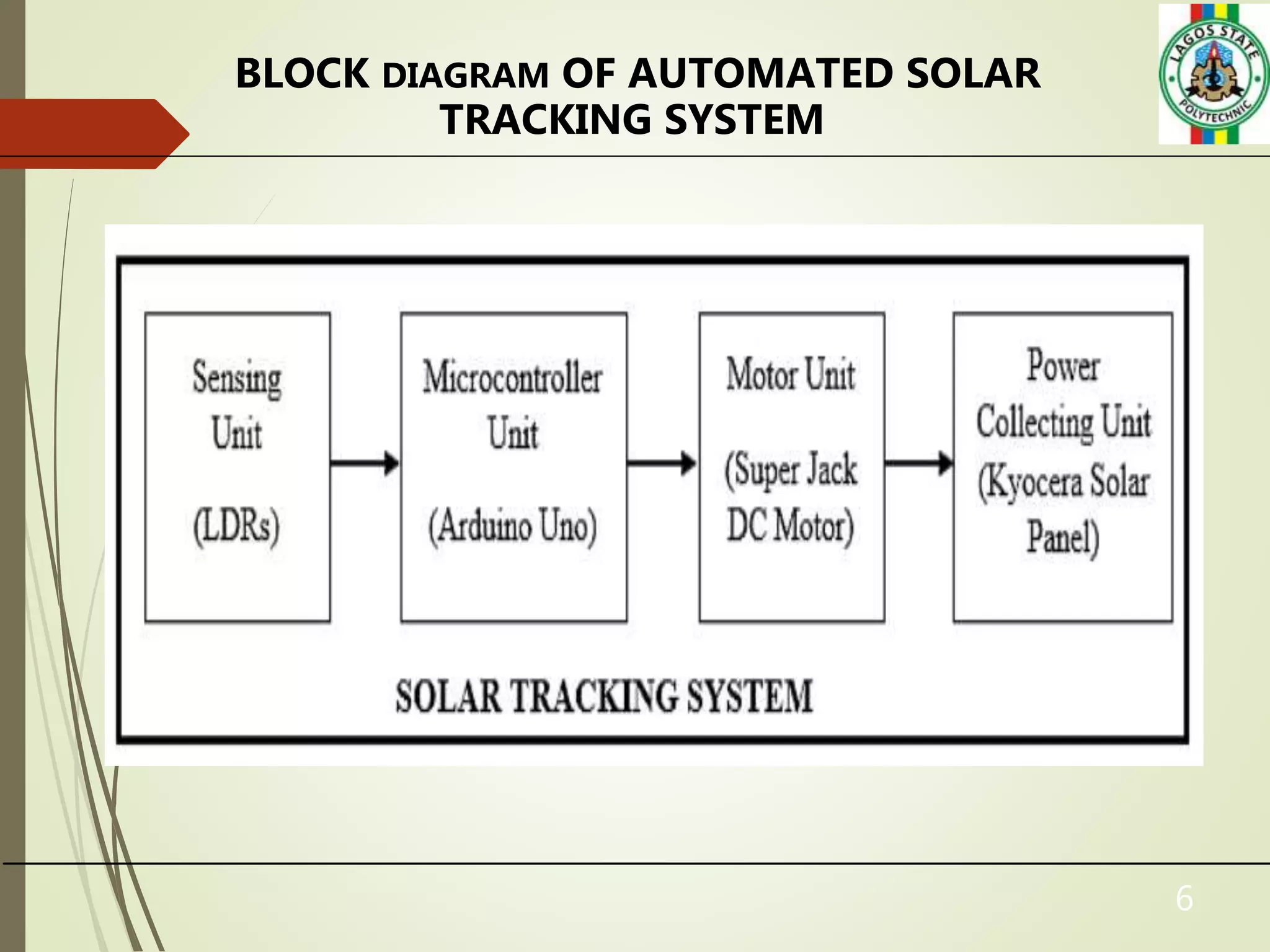
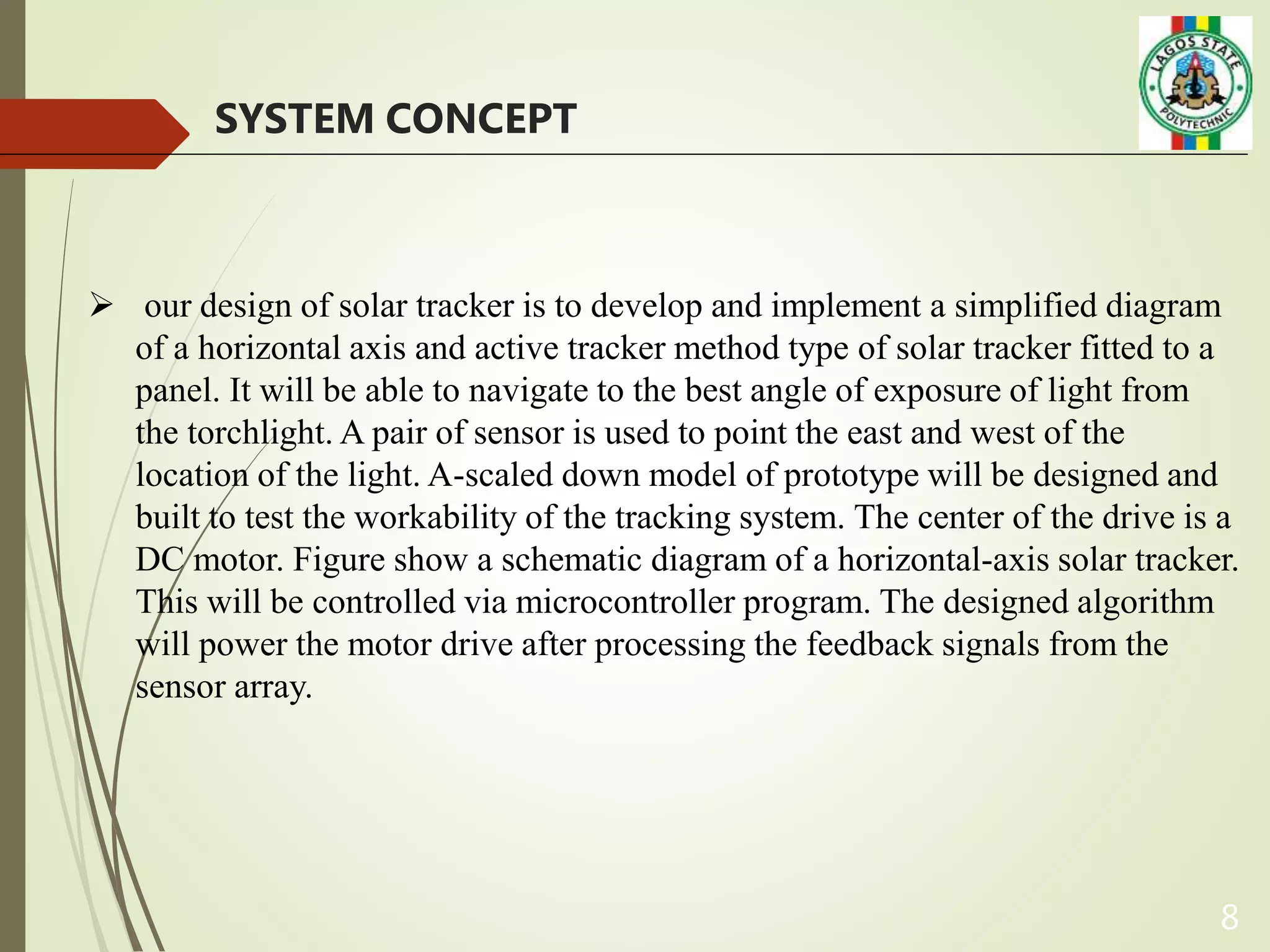
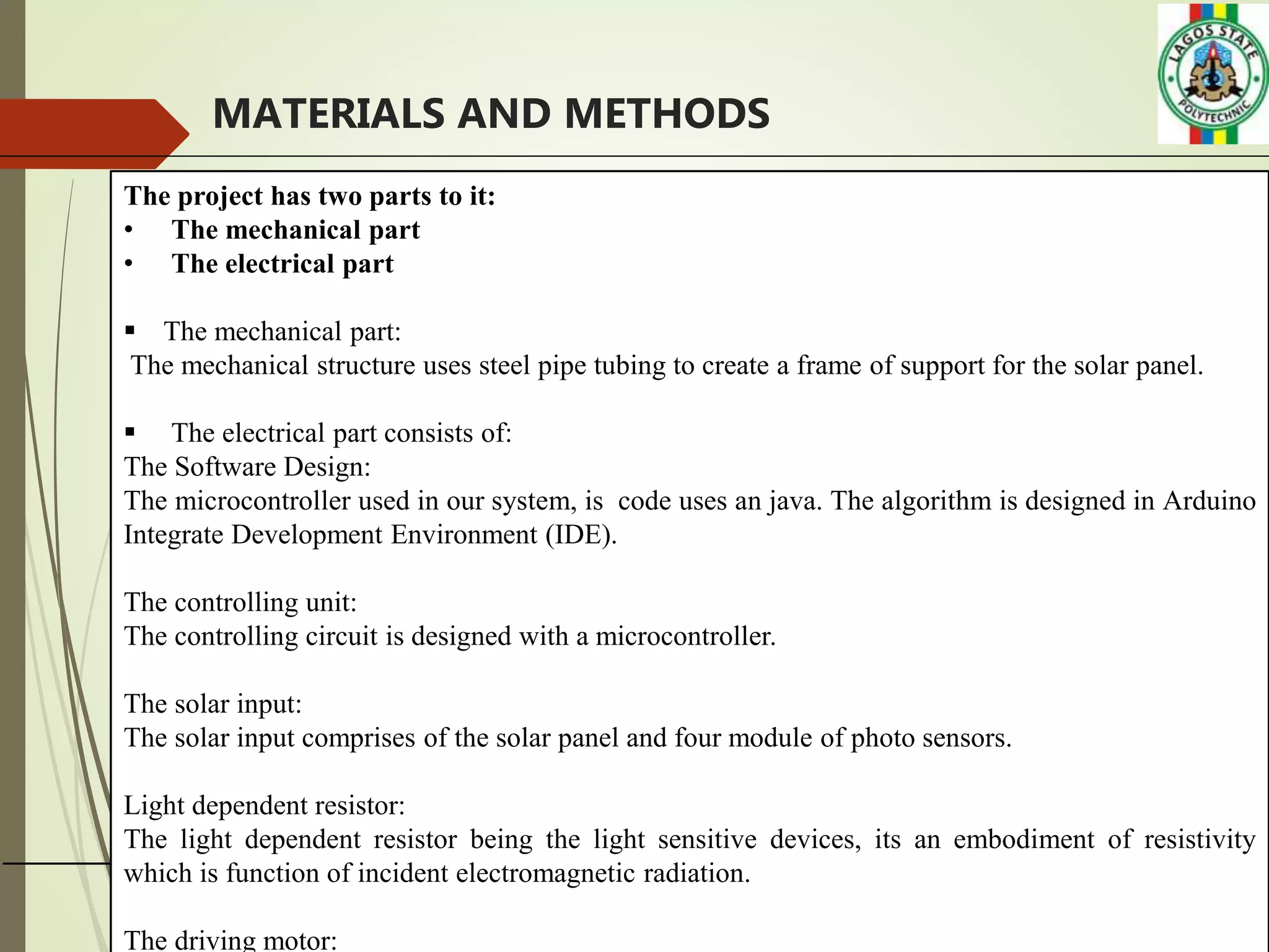
DESIGN AND CONTRUCTION OF AN AUTOMATIC SOLAR
TRACKING SYSTEM
By
ABIDOYE OLUWATOBILOBA O. [1902071001]
TESLIM ABDULATEEF OLAWALE [1902071020]
ANIMASHAUN QUADRI OLASUKANMI [1902071019]
AKINFENWA OLUWASEYI EMMANUEL [1902071021]
Department of Mechatronics Engineering School of Engineering,
Lagos State Polytechnic, Ikorodu, Lagos, Nigeria.
2
CONTENTS
 Introduction
 Objective
 Review of Literature
 Aims and Objectives
 Basic Components
 Advantages and Disadvantages
 Conclusions
INTRODUCTION
This is a solar tracking system which can be used as a power generating method
from sunlight. This method of power generation is simple and is taken from natural
resource . This needs only maximum sunlight to generate power. This project helps
for power generation by setting the equipment to get maximum sunlight
automatically. This system is tracking for maximum intensity of light. When there is
decrease in intensity of light, this system automatically change its direction to get
maximum intensity of light.
4
OBJECTIVES
Our project objectives is based on the following objectives
Ability to automatically rotate the tracker with the usage of a controller alongside
the overall ecliptic.
The solar panel tracks the sun from east to west mechanically for maximum
intensity of light
To consume maximum solar energy through solar tacking panel
Design and improve a solar panel
High performance and efficiency of solar panel
5
REVIEW OF LITERATURE
 Dual-axis trackers: Dual-axis trackers have two degrees of freedom that act as axes
of rotation. These axes are typically normal to one another. Dual axis trackers allow
for optimum solar energy levels due to their ability to follow the sun vertically and
horizontally.
Dual Axis Tracker
6
BLOCK DIAGRAM OF AUTOMATED SOLAR
TRACKING SYSTEM
7
COMPONENTS USES
• Solar panels
• DC motors
• The tracking controller
• Light Dependent Resistor (LDR)
• Push button switch
• Voltage regulator
• Microcontroller (Arduino)
8
SYSTEM CONCEPT
 our design of solar tracker is to develop and implement a simplified diagram
of a horizontal axis and active tracker method type of solar tracker fitted to a
panel. It will be able to navigate to the best angle of exposure of light from
the torchlight. A pair of sensor is used to point the east and west of the
location of the light. A-scaled down model of prototype will be designed and
built to test the workability of the tracking system. The center of the drive is a
DC motor. Figure show a schematic diagram of a horizontal-axis solar tracker.
This will be controlled via microcontroller program. The designed algorithm
will power the motor drive after processing the feedback signals from the
sensor array.
9
MATERIALS AND METHODS
The project has two parts to it:
• The mechanical part
• The electrical part
 The mechanical part:
The mechanical structure uses steel pipe tubing to create a frame of support for the solar panel.
 The electrical part consists of:
The Software Design:
The microcontroller used in our system, is code uses an java. The algorithm is designed in Arduino
Integrate Development Environment (IDE).
The controlling unit:
The controlling circuit is designed with a microcontroller.
The solar input:
The solar input comprises of the solar panel and four module of photo sensors.
Light dependent resistor:
The light dependent resistor being the light sensitive devices, its an embodiment of resistivity
which is function of incident electromagnetic radiation.
The driving motor:
10
CONCLUSIONS
 We presented a mean of tracking the suns position with the help of
microcontroller. Specially, it demonstrate a working software solution for
maximising solar cell output by positioning the solar panel at the point of
maximum light intensity.
 Moreover, the tracker can initialize the starting position itself which reduce the
need of any more resistors.
 Though the prototype has limitations in hardware areas as an initial set up, still it
provides an opportunity for improvement of the design methodology in future.
Final project structure
Thank you for listening !!!!!!
Any question ?
12

Power_Point_PresentationTemplate_Mechanical_20.pptx

  • 1.
    DESIGN AND CONTRUCTIONOF AN AUTOMATIC SOLAR TRACKING SYSTEM By ABIDOYE OLUWATOBILOBA O. [1902071001] TESLIM ABDULATEEF OLAWALE [1902071020] ANIMASHAUN QUADRI OLASUKANMI [1902071019] AKINFENWA OLUWASEYI EMMANUEL [1902071021] Department of Mechatronics Engineering School of Engineering, Lagos State Polytechnic, Ikorodu, Lagos, Nigeria.
  • 2.
    2 CONTENTS  Introduction  Objective Review of Literature  Aims and Objectives  Basic Components  Advantages and Disadvantages  Conclusions
  • 3.
    INTRODUCTION This is asolar tracking system which can be used as a power generating method from sunlight. This method of power generation is simple and is taken from natural resource . This needs only maximum sunlight to generate power. This project helps for power generation by setting the equipment to get maximum sunlight automatically. This system is tracking for maximum intensity of light. When there is decrease in intensity of light, this system automatically change its direction to get maximum intensity of light.
  • 4.
    4 OBJECTIVES Our project objectivesis based on the following objectives Ability to automatically rotate the tracker with the usage of a controller alongside the overall ecliptic. The solar panel tracks the sun from east to west mechanically for maximum intensity of light To consume maximum solar energy through solar tacking panel Design and improve a solar panel High performance and efficiency of solar panel
  • 5.
    5 REVIEW OF LITERATURE Dual-axis trackers: Dual-axis trackers have two degrees of freedom that act as axes of rotation. These axes are typically normal to one another. Dual axis trackers allow for optimum solar energy levels due to their ability to follow the sun vertically and horizontally. Dual Axis Tracker
  • 6.
    6 BLOCK DIAGRAM OFAUTOMATED SOLAR TRACKING SYSTEM
  • 7.
    7 COMPONENTS USES • Solarpanels • DC motors • The tracking controller • Light Dependent Resistor (LDR) • Push button switch • Voltage regulator • Microcontroller (Arduino)
  • 8.
    8 SYSTEM CONCEPT  ourdesign of solar tracker is to develop and implement a simplified diagram of a horizontal axis and active tracker method type of solar tracker fitted to a panel. It will be able to navigate to the best angle of exposure of light from the torchlight. A pair of sensor is used to point the east and west of the location of the light. A-scaled down model of prototype will be designed and built to test the workability of the tracking system. The center of the drive is a DC motor. Figure show a schematic diagram of a horizontal-axis solar tracker. This will be controlled via microcontroller program. The designed algorithm will power the motor drive after processing the feedback signals from the sensor array.
  • 9.
    9 MATERIALS AND METHODS Theproject has two parts to it: • The mechanical part • The electrical part  The mechanical part: The mechanical structure uses steel pipe tubing to create a frame of support for the solar panel.  The electrical part consists of: The Software Design: The microcontroller used in our system, is code uses an java. The algorithm is designed in Arduino Integrate Development Environment (IDE). The controlling unit: The controlling circuit is designed with a microcontroller. The solar input: The solar input comprises of the solar panel and four module of photo sensors. Light dependent resistor: The light dependent resistor being the light sensitive devices, its an embodiment of resistivity which is function of incident electromagnetic radiation. The driving motor:
  • 10.
    10 CONCLUSIONS  We presenteda mean of tracking the suns position with the help of microcontroller. Specially, it demonstrate a working software solution for maximising solar cell output by positioning the solar panel at the point of maximum light intensity.  Moreover, the tracker can initialize the starting position itself which reduce the need of any more resistors.  Though the prototype has limitations in hardware areas as an initial set up, still it provides an opportunity for improvement of the design methodology in future.
  • 11.
  • 12.
    Thank you forlistening !!!!!! Any question ? 12